Note: Descriptions are shown in the official language in which they were submitted.
Docket No. 1071-IR-PA
~0538~9
APPARATUS FOR SCREENING TO l~MOVE KNOTS FROM A
FLUID BORNE SLURRY OF FIBERS AND KNOTS
BACKGROUND OF THE INVENTION
This invention relates generally to separation
of very large particles from a fluid borne stream of
relatively fine particles by screening, and more
particularly to coarse screening devices for washing
05 and draining fine fiber/liquid suspension away from
coarse nodules and/or other large particles.
For example in the digestion of wood for
pulpmaking, a small fraction of chips become masked
by other chips or are sufficiently digestion
resistant to survive the digestion process and are
commonly called knots. These and other undigested
particles must be removed from the fluid borne pulp
stream to prevent clogging of processing equipment
and, ultimately, degradation of paper quality.
Removal of knots is normally accomplished in a
knotter which screens the process slurry to remove
them. A significant quantity of acceptable pulp is
discharged along with the knots being rejected. This
pulp must be separated from the knots before the
knots are reprocessed or otherwise disposed of. In
Docket No. 1071-IR-PA 2~3819
most cases, separation is accomplished in a knot
drainer, which is a coarse screen which separates
knots from pulp fibers and discharges the knots in a
relatively dry and fiber free condition.
05 "Secondary" knot drainers, commonly consist of
either high speed vibratory screens or generally
vertical screw drainers. These may permit air
entrainment with consequent foam generation which can
adversely affect the process and require excessive
defoamer consumption. In the screw type knot
drainers, relative motion by the conveying screw and
the screen plate can cause size reduction of the
suspended particles. This "comminution" of knots can
result in fibrous and resinous debris which is
difficult to remove in downstream processing and
which can degrade paper quality. Another consequence
of using either type of secondary knot drainer may be
discharge of an excessive amount of fiber with the
knots. This fiber must either be recovered in
further processing or be lost to production. Because
of vibration and wear, maintenance costs for repair
and replacement of screens and other components as
well as lost production due to downtime for repairs
can be unacceptably high. These and other
disadvantages can reduce the eIEiciency of the knot
removal and knot draining operation and hence
Docket No. 1071-IR-PA 2 0 ~ 3 8 i g
increase the cost of producing clean pulp.
The foregoing illustrates limitations known to
exist in present screening devices for removing
coarse particles from a liquid borne fine particle
05 slurry such as the various pulp types used in
papermaking. Thus, it is apparent that it would be
advantageous to provide an alternative directed to
overcoming one or more of the limitations set forth
above. Accordingly, a suitable alternative is
provided including features more fully disclosed
hereinafter.
SUMMARY OF THE INVENTION
In one aspect of the present invention, this is
accomplished by providing a screening apparatus for
separating coarse solid particles from a fluid borne
slurry, including a substantially vertical housing
having a feed chamber located near the bottom of the
housing for receiving a fluid borne suspension of
very fine and very coarse solid particles. A
screening chamber is provided within the housing
above and communicating with the feed chamber and
bounded by a rotatable cylindrical screen. A fine
particle accepts chamber is located within the
housing radially outboard of the screen and has a
fine particle accepts outlet. A fluid free coarse
Docket No. 1071-IR-PA
20~S19
particle discharge outlet is located at the top of
the housing in communication with the screening
chamber below. A conveyor device is operatively
associated with the screen for transporting the
05 coarse particles upward through the screening chamber
to the fluid free coarse particle chamber and
outlet.
The foregoing and other aspects will become
apparent from the following detailed description of
the invention when considered in conjunction with the
accompanying drawing figures.
BRIEF DESCRIPTION OF THE DRAWING FIGURES
Fig. 1 is a schematic partially sectional
elevation view of the knot drainer of the present
invention;
Fig. la shows the tramp particle accumulator and
discharge arrangement;
Fig. 2 is a fragmentary elevation view taken in
circled area 2 of Fig. 1 showing the knot/fiber wash
nozzle;
Docket No. 1071-IR-PA ~ 819
Fig. 3 is a plan view from line 3-3 of Fig. 2
showing more detail of the wash nozzle;
Fig. 4 is a plan view from line 4-4 of Fig. 1
showing the knot discharger;
05 Fig. 5 is a plan view from line 5-5 of Fig. 1
showing the grit separator;
Fig. 6 is a fragmentary elevation view of a
knot drainer showing the level control device of the
present invention;
Fig. 7 is a fragmentary elevation view
showing an optional hydrodynamic backwash pulse
generator;
Fig. 8 is a plan view from line 8-8 of
Fig. 7;
Fig. 9 is a plan view of an alternative form
of the pulse generator of the present invention;
and
Fig. 10 is an elevation view from line 10-10 of
Fig. 9-
Docket No. 1071-IR-PA 2 Q ~ 3 ~19
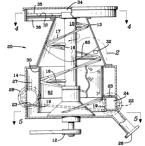
DETAILED DESCRIPTION
Fig~ 1 shows several features of the knot
drainer 20 of the present invention. Its housing is
made up of a lower cylindrical section 14, an upper
extension 13 formed in this instance as a truncated
05 cone, and a fluid free coarse particle chamber 34 at
the top.
A fluid borne slurry of fine particles together
with very coarse particles is tangentially fed
through inlet connection 22 an(~ passes through feed
chamber 24 in a circular path. Feed chamber 24 is
bounded by inner wall 19, outer housing 14, and roof
23 which spirals downward from inlet 22 until it
approaches the bottom of the inner wall 19 where it
ends. The tangential feed path of the slurry imparts
centrifugal force to the slurry and causes grit,
stones, and other heavy tramp materials to be carried
along at the housing wall 14 and finally to be
deposited, for example, into a combined grit
accumulator and discharge nozzle 26.
Since inner walls 19 end above the bottom of
housing 14, the slurry enters the processing portion
of the knot drainer by flowing under inner wall 19.
Rotor shaft 15, which extends vertically at the
center of the knot drainer, is supported on rotor
Doc~:et No. 1071-IR-PA2~ 5 3 819
base 11 which contains the standard bearings and
seals required for pulp processing equipment. The
rotor is driven through sheave wheels or other drive
member 12 beneath the housing 14. A screw flight 17
05 begins near the bottom of inner wall 19 but more
normally begins near the bottom of screen cylinder 30
and spirals to the top of housing extension 13. In
the preferred embodiment, three flights 17 are
provided, but for the sake of clarity, only one is
illustrated here. Flights 17 are connected to rotor
shaft 15 through brackets 16. A substantially
cylindrical screen 30, which extends axially from
about the top of inner wall 19 to slightly above the
top of cylindrical housing 14, is firmly attached to
the outer edge of the spiral flights 17. The upper
portions of spiral flights 17 turn freely relative to
the truncated conic section which forms the wall of
housing extension 13. Screen 30 is sized to fit very
closely to inner wall 19 and the upper flange of
cylindrical housing 14 so that, although it is free
to rotate relative to the walls, it is close enough
to effectively prevent passage of undesirably large
particles from screening chamber 62 into accepts
chamber 27. Accepts chamber 27 is bounded on the
outside by cylindrical housing 14, on top by the
upper flange of cy,lindrical housing 14, on the bottom
by roof 23 of inlet chamber 24, and on the inside
Docket No. 1071-IR-P 2 0 ~ 3 819
partly by a portion of inner wall 19 and partly by
cylindrical screen 30.
During operation, the vortex fluid surface 65 in
the knot drainer is essentially concave as
05 illustrated. Accept pressure of the slurry is
adjusted to maintain the fluid level substantially as
shown above screening chamber 62. This keeps the
screen and the accepts chamber completely flooded so
that foam formation will be minimized. The accepts
slurry passes through screen 30 into accepts chamber
27 and is returned to the pulp processing stream
through accepts outlet 28. Slightly above the top of
screen 30 a nozzle 32 for introducing fiber free wash
liquor is provided. A more detailed view of the area
within circle 2 of Fig. 1 is shown in Fig. 2 while a
plan view from line 3-3 of Fig. 2 is presented in
Fig. 3. From these it can be seen that nozzle 32
introduces the fiber free wash liquor in the
direction of travel of spiral flight 17, which is
connected through bracket 16 with rotor shaft 15.
Flights 17 describe helices of p]-ogressively
decreasing diameters within housing extension 13.
This allows them to rotate freely while maintaining a
very close proximity to housing extension 13.
Housing extension 13 is preferably provided in
Docket No. 1071-IR- ~ o~ 3
the truncated cone shape illustrated although a
straight cylindrical form is also possible. This
provides the advantages of a steep contact angle
between the fluid surface 65 and extension wall 13
05 which prevents liquid spillage into knot discharger
34, reduces turbulence and foam formation, and
improves drainage of knots on the flights 17 above
fluid surface 65. This improves elutriation
performance of nozzle 32 and thus provides higher
knot draining efficiency.
Knot discharger 34 is shown at the top of knot
drainer 20. It consists of a flat annular surface 38
attached at the top of housing extension 13. Rotor
shaft 15 and flights 17 extend into the discharger
where knots, as they arrive from the flights, are
swept around surface 38 and outward to discharge
outlet 36 by sweeper bars 35. This can be seen by
observing Fig. l and Fig. 4 which is a plan view from
line 4-4 of Fig. 1.
Fig. 5 is a plan view from line 5-5 of Fig. 1 to
show the opening of the discharge nozzle 26 for grit,
stones, metal and other heavy tramp material. The
lower extremity of inner wall 19 is shown. As seen
in Fig. 1, this member ends some distance above the
bottom of housing 14 to permit entry of the feed
Docket No. 1071-IR-P~ ~ 5 3 ~ 1 9
slurry into screening chamber 62. The shadow of
inlet 22 is shown to indicate the relative location
of discharge nozzle 26 with respect thereto. The
area outside inner wall 19 is the extension of feed
05 chamber 24 which would be seen once the spiral roof
of feed chamber 24 has reached the bottom of inner
wall 19. Because of the higher density of the tramp
metal, stones, and grit particles, they are
vigorously thrust outward by the centrifugal force
imparted by the downward spiralling inlet flow. This
causes them to pass into and accumulate in discharge
nozzle 26 above normally closed valve 91, as shown in
Fig. la. Periodically, valve 92 is closed and valve
91 is opened to release the particles from nozzle 26
lS allowing accumulated tramp particles to fall into
tramp particle accumulator 90. Then valve 91 is
returned to closed position and the contents of
accumulator 90 may be dumped by opening valve 92.
Also shown in Fig. 5 is rotor base 11, rotor shaft
15, a support bracket 16, and the beginning of a
spiral flight 17 which may be coextensive with the
bottom extremity of inner wall 19. Employment of
tramp particle accumulator 90 of Fig. la is an
optional embodiment, as there may be preferable
discharge means other than the two valve trap shown.
Fig. 6 shows an optional level control system
Docket No. 1071-IR-
20538 1 9
for use with the present invention. It includes a
downward extension of the stationary truncated conic
housing extension 13. This downward extension is a
vortex breaker 40 and is approximately axially
05 coextensive with screen 30. It is shown in the
figure as a perforated plate, but it may also be
provided with vertical slots. With either holes or
slots, vortex breaker 40 substantially eliminates the
tangential flow of the accepts slurry and leaves only
the radial component of flow. Level control weir 45
separates accepts chamber 27 from vortex chamber 42a
and radial flow chamber 42b. As the slurry flows
over weir 45 from radial flow chamber 42b, it pours
over and through anti-splash baffle 47 into accepts
chamber 27. Baffle 47 reduces air entrainment by
further reducing the turbulence of the slurry flow.
Vent 50 is provided at the top of level control
chamber 49 to permit escape of any air released from
the slurry.
Figs. 7, 8, 9, and 10 illus~,rate two embodiments
of a backwash device of the present invention which
is provided to prevent occlusion of the apertures of
screen 30 by knots and other coarse particles.
The embodiment shown in Figs. 7 and 8 consists
of a hydrodynamic foil 80 which is axially
Docket No. 1071-IR-PA 2 Q ~ 3 8 1 9
coextensive with and positioned outboard of screen 30
and in close radial proximity thereto. As the
rotating screen 30 passes foil 80 the fluid borne
slurry between them receives a pressure pulse which
05 backwashes the screen apertures to expel knots which
may otherwise plug the apertures.
An alternative embodiment of the hydrodynamic
foil 82 is shown in Figs. 9 and 10. In this case,
foil 82 consists of an overhang 83 and two "heels"
84. Between heels 84 is a passage 85 through which
the accepts slurry together with small coarse
particles can escape. The geometry of foil 82 causes
it to act like a flat fluid collection funnel with
its inlet bounded by overhang 83 and screen 30 and
its outlet 85 defined by heels 84 and screen 30. The
standoff distance of overhang 83 from screen 30 is
approximately the same dimension as the diameter or
width of the screen apertures. This assures that
small coarse particles which pass through the screen
will not collect and jamb between foil 82 and screen
30.
Operation of a knot drainer, including all
features described and illustrated in the figures,
begins with intro,d,uction of the knot containing pulp
slurry at inlet connection 22. From there it passes
.,,. i,.,.,.. -. . . - . -
Docket No. 1071-IR-PA'2 0 5 3 8 1 9
through inlet chamber 24 bounded by inner wall 19,
cylindrical housing 14, and spiral roof 23.
Centrifugal force generated by the tangential inlet
and the confined circular flow path of the slurry
05 causes heavy tramp particles to be segregated at the
outer boundary of feed chamber 24 and to pass into
nozzle 26 and thence through valve 91 when open into
tramp particle accumulator 9o or other tramp particle
accumulation system. The knot bearing pulp slurry,
10 meanwhile, flows beneath inner wall 19 and upward
into screening chamber 62. At the bottom of inner
wall 19, the fluid borne slurry encounters spiral
flights 17 which act as a screw conveyor to carry
knots and pulp upward into screening chamber 62.
15 Screening chamber 62 is that volume bounded by
rotating cylindrical screen 30. Accepts chamber 27
is radially outboard of screen 30 and is drained
through accepts discharge nozzle 28. Spiral flight
17 and rotating cylindrical screen 30 are firmly
20 attached so that they rotate together. Rotary motion
is transmitted from rotor shaft 15 to spiral flights
17 through support brackets 16. The knot bearing
pulp slurry is screened by the apertures in screen 30
so that most of the accepts slurry is separated from
25 the knots which are transported on rotating flights
17 through the scxeening chamber 62.
13
Docket No. 1071-IR-PA 2 ~ 5 3 ~ 19
To prevent plugging of the apertures of screen
30, at least one backwash pulse inducer 80 or 82 is
provided in accepts chamber 2 7. The pressure
pulsations induced in the screen apertures as they
05 pass the pulse inducer 80 or 82 expel fiber plugs to
maintain flow through the apertures and also expel
knots so that they continue their transport along
rotating flights 17. The fluid surface 65 is concave
due to the centrifugal forces imparted by the rotor.
Slightly above screening chamber 62 but below liquid
surface 65, a nozzle 32, tangentially fixed in
stationary housing extension wall 13, introduces
substantially fiber free liquor to release fibers
from the reject knots. This liquor is introduced in
15 the same direction as the rotation of spiral flights
17 in order to minimize turbulence and energy
consumption and to prevent air entrainment. The
fibers thus released are carriecl downward through the
screening chamber 62 and pass into accepts chamber
20 27. The knots are transported upward on rotating
flights 17 by the drag of the knots on the inclined
stationary wall 13. Once above liquid surface 65,
the knots quickly drain to a relatively dry condition
as they are carried upward to discharge chamber 34.
25 In one embodiment, knots are deposited on the flat
annular surface 38 of the discharger and are impelled
by discharger sweeper arms 35 and carried around and
Docket No. 1071-IR-P~ Q ~ 3 ~ 1 ~
outward to knot discharger nozzle 36 where they are
expelled in a substantially fiber free and relatively
dry condition.
In cases where the level control feature is
05 included, the fluid level in the knot drainer will be
determined by the height of level control weir 45.
Acceptable pulp slurry passe-; through rotating
cylindrical screen 30, into vortex chamber 42a,
through vortex breaker plate 40, which has a
thickness greater than the width of its apertures
such that substantially all of the tangential
component of flow is suppressed and only the radial
component remains, and into radial flow chamber 42b.
The slurry thus flows smoothly over weir 45 and into
accepts chamber 27 by passing over and through
anti-splash baffle 47. The combination of the weir
and the anti-splash baffle reduces air entrainment by
limiting turbulence so that foaming is minimized and
the pulp slurry discharge through accepts discharge
nozzle 28 requires little if any defoamer. At the
top of level control chamber 49 is vent 50 which is
provided to permit the exit of any air released from
the pulp slurry within the chamber.
The screen backwash function described herein
could be performed by one or more slotted nozzle
Docket No. 1071-IR-P~ 05 3 8 1 9
through which fiber free liquor is introduced, but
that can cause unacceptable dilution. Hence, the
hydrodynamic pulse inducers are preferable for that
purpose.
OS Provision of a rotating radially symmetrical
screen, whether conic or cylindrical, integrally
connected to the spiral flight conveyor eliminates a
source of often severe damage in knotters and knot
drainers of standard configuration. Stones or other
hard tramp particles which enter the screening
chamber of a standard knotter or knot drainer are
very likely to lodge between the stationary screen
and the moving rotor or hydrofoil causing severe wear
and damage to both members. In the present
invention, stones or hard tramp particles that may
escape the grit and tramp particle discharge
provision will be carried upward on the spiral
flight, but, since there is no relative motion
between the spiral flights and the screen, the
particles will merely roll or slide along the screen
surface without any grinding or jamming behavior.
Continuation of the spiral flight above the liquid
level of the knot drainer permits discharge of
substantially dry fibre free knots and a consequent
reduction in the àmount of reprocessing necessary.