Language selection

Search

Patent 2053877 Summary

Third-party information liability

Some of the information on this Web page has been provided by external sources. The Government of Canada is not responsible for the accuracy, reliability or currency of the information supplied by external sources. Users wishing to rely upon this information should consult directly with the source of the information. Content provided by external sources is not subject to official languages, privacy and accessibility requirements.

Claims and Abstract availability

Any discrepancies in the text and image of the Claims and Abstract are due to differing posting times. Text of the Claims and Abstract are posted:

  • At the time the application is open to public inspection;
  • At the time of issue of the patent (grant).
(12) Patent Application: (11) CA 2053877
(54) English Title: APPARATUS FOR ASSEMBLING SLATS OF VENETIAN BLINDS
(54) French Title: APPAREIL UTILISE POUR L'ASSEMBLAGE DES LAMES DE STORE VENITIEN
Status: Dead
Bibliographic Data
(51) International Patent Classification (IPC):
  • E06B 9/266 (2006.01)
(72) Inventors :
  • HEBSGAARD, JENS OVE (Denmark)
(73) Owners :
  • A/S CHR. FABERS FABRIKER (Denmark)
(71) Applicants :
(74) Agent: FETHERSTONHAUGH & CO.
(74) Associate agent:
(45) Issued:
(86) PCT Filing Date: 1990-04-17
(87) Open to Public Inspection: 1990-10-26
Examination requested: 1997-04-10
Availability of licence: N/A
(25) Language of filing: English

Patent Cooperation Treaty (PCT): Yes
(86) PCT Filing Number: PCT/DK1990/000098
(87) International Publication Number: WO1990/012947
(85) National Entry: 1991-10-24

(30) Application Priority Data:
Application No. Country/Territory Date
1992/89 Denmark 1989-04-25

Abstracts

English Abstract


ABSTRACT

A machine for production of finished lath packs for
venetian blinds, which have holes at the ends for draw
cords and ladders (3) consisting of bands or strings,
every cross band of which carries a lath, and where two
neighbouring cross bands of a ladder are placed on each
side of the draw cord passed through the holes (8), which
machine has a mechanism which inserts laths (2) one by one
over a cross hand in the suspended ladders (3) and at each
ladder a mechanism (1) which lifts the inserted lath and
the ladders (3) as well as devices to retain the raised
lath. Each lifting mechanism has a carrier (1) with a
slit through which the ladder (3) stretches and, on both
sides of the slit, carrier faces (5) sloping away from
each other for an inserted lath (2). The carrier can tilt
in such a way that the carrier faces support the laths
alternately. The carriers are tilted synchronously with
the movement of the feed mechanism. The carrier (1) is
thus used also for positioning the ladder with the
consecutive cross bands placed on one and the other side
alternately of the draw cord.


Claims

Note: Claims are shown in the official language in which they were submitted.


WO 90/12947 PCT/DK90/00098
- 3 -

Amended Claims

1. A machine for production of finished lath packs for
Venetian lath blinds, the superjacent laths (2,2') of which
have punched holes (8) at least at the ends for draw cords
and with ladders (3) consisting of bands or strings, every
cross band of which carries a lath, and where one of two
neighbouring cross bands of a ladder is placed on one side
while the other is placed on the other side of a draw cord
passed through the punched holes (8), which machine has a
mechanism which inserts laths (2) one by one over a cross
band in the suspended ladders (3) and at each of the sus-
pended ladders a mechanism (l) which lifts the inserted
lath and the ladders (3) so that the next lath is inserted
over the following cross band of the ladders as well as de-
vices to retain the raised lath, characterized in that
each lifting mechanism has a carrier (1) with a slit
through which the suspended ladder (3) stretches and, on
both sides of the slit, carrier faces (5) sloping away from
each other for an inserted lath (2), which carrier can turn
on an axis (6) stretching across the lower side of the in-
serted lath between one end position where one carrier face
supports the lath and another end position where the other
carrier face supports the lath which machine also has de-
vices (9-12) to swing the carriers (1) from one end posi-
tion to the other synchronously with the movement of the
feed mechanism.

2. A machine as claimed in claim 1, characterized in that
a downward arm (9) and a curve roller (10) are fixed to
each carrier (1) and that devices swinging by the carriers
include a push bar (12) reciprocated by the feed mechanism
under the inserted laths (2), to which push bar guide
plates (11) are fixed which work together with the said
curve rollers.

Description

Note: Descriptions are shown in the official language in which they were submitted.


WO90tl2947 PCT/DK90/00~98
;~C53877
APPARATUS FO~ ASSEM~LING SL~TS OF VENETIAN BLINDS
The present invention relates to a machine for production of
finished packs of Venetian blind laths of the kind described
in the introduction to claim 1.

A machine of the said kind is known from US letters patent ~o.
4,516,300 where the ladder fro~ a ladder supply is guided
through a guide mechanism located under the inserted lath.
In a further not specified manner this guide mechanism can
be tilted from one end position to another whenever the
inserted lath and the ladder are lifted so that the ladder
cross band is placed on one and the other side alternately of
the draw cord.

Designing the device according to the invention as described
in claim 1 has the result that the same machine element, i.e.
the carrier, is utilïzed for both lifting the inserted laths
and guiding and placing the ladder correctly, i.e. with the
consecutive cross bands placed on one and the other side
alternately of the draw cord.
The devices used to swing the carrier~ synchronously with the
insertion of laths may, for example, include drives activated
by a swi~ch mounted in the feed path for the laths. However,
a simpler and more dependable design is shown in claim 2.
In what follows, the invention is described fùrther in connec-
tion with the drawing where

Fig. 1 shows the parts of a machine ~or production of Venetian lath blinds after insertion of a lath,
which parts are important to the invention,
and

Fig. 2 the same parts, but after insertion of the
following lath.

W090/12947 PCT/DK90/00098
2 ZC. 3S77

The machine shown on the drawing includes a numher of iden-
tical work stations, viz. a station for each ladder band with
which the Venetian lath bland is to be provided depending on
the dimensions of the laths.
Each work station has carrier 1 to support the last inserted
lath 2 in a known way which is irrelevant to the invention.
The carrier 1 has a slit through which a ladder 3 consisting
of bands or strings stretches downward from previously in-
serted laths 2' and/or a separate holder 4 to a ladder supplynot shown. On both sides of the slit the carrier 1 has carrier
faces 5 which slope away from each other on both sides of the
slit and turn on an axis 6 stretching across the lower side
of the inserted lath 2. The carrier 1 can be swung between a
position in which one carrier face 5 supports a lath 2 and
another position in which the other carrier face supports a
lath. The swing is effected in a way described later so that
the two carrier faces alternately support consecutive laths.
The carrier 1 lifts the lath 2 so that it is gripped by pawls
7 in a magazine, and when the carrier moves down it is turned
because of the special design of the guide plate 11. On
account of the swing the suspended ladder is moved at the
same time so that the cross bands are on one and the other
side alternately of a punched hole 8 in laths 2,2'.
A downward arm ~ is fixed to the carrier ~ of the shown
embodiment. A roller lO which works together with a guide
plate 11 is fixed to the lower end of the arm. The guide disc
is fixed to a push bar 12 which can reciprocate synchronously
30 with the feed mechanism for laths 2,2 , not shown. The guide
plate 11 is designed in such a way that the carrier 1 is
swung as described above whenever a lath 2 is inserted and
supported by a carrier face 5.


. . , - .
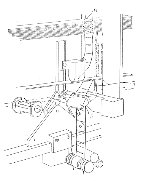
Representative Drawing
A single figure which represents the drawing illustrating the invention.
Administrative Status

For a clearer understanding of the status of the application/patent presented on this page, the site Disclaimer , as well as the definitions for Patent , Administrative Status , Maintenance Fee  and Payment History  should be consulted.

Administrative Status

Title Date
Forecasted Issue Date Unavailable
(86) PCT Filing Date 1990-04-17
(87) PCT Publication Date 1990-10-26
(85) National Entry 1991-10-24
Examination Requested 1997-04-10
Dead Application 2000-04-17

Abandonment History

Abandonment Date Reason Reinstatement Date
1999-04-19 FAILURE TO PAY APPLICATION MAINTENANCE FEE
1999-05-27 R30(2) - Failure to Respond

Payment History

Fee Type Anniversary Year Due Date Amount Paid Paid Date
Application Fee $0.00 1991-10-24
Maintenance Fee - Application - New Act 2 1992-04-17 $100.00 1992-03-05
Maintenance Fee - Application - New Act 3 1993-04-19 $100.00 1993-04-15
Registration of a document - section 124 $0.00 1993-04-30
Maintenance Fee - Application - New Act 4 1994-04-18 $100.00 1994-04-12
Maintenance Fee - Application - New Act 5 1995-04-17 $150.00 1995-04-18
Maintenance Fee - Application - New Act 6 1996-04-17 $150.00 1996-04-15
Request for Examination $400.00 1997-04-10
Maintenance Fee - Application - New Act 7 1997-04-17 $150.00 1997-04-10
Maintenance Fee - Application - New Act 8 1998-04-17 $150.00 1998-04-09
Owners on Record

Note: Records showing the ownership history in alphabetical order.

Current Owners on Record
A/S CHR. FABERS FABRIKER
Past Owners on Record
HEBSGAARD, JENS OVE
Past Owners that do not appear in the "Owners on Record" listing will appear in other documentation within the application.
Documents

To view selected files, please enter reCAPTCHA code :


To view images, click a link in the Document Description column. To download the documents, select one or more checkboxes in the first column and then click the "Download Selected in PDF format (Zip Archive)" or the "Download Selected as Single PDF" button.

List of published and non-published patent-specific documents on the CPD .

If you have any difficulty accessing content, you can call the Client Service Centre at 1-866-997-1936 or send them an e-mail at CIPO Client Service Centre.


Document
Description 
Date
(yyyy-mm-dd) 
Number of pages   Size of Image (KB) 
Representative Drawing 1999-09-24 1 33
Cover Page 1994-03-12 1 18
Abstract 1994-03-12 1 29
Claims 1994-03-12 1 43
Drawings 1994-03-12 2 75
Description 1994-03-12 2 80
Assignment 1991-10-24 9 319
Prosecution-Amendment 1999-03-19 5 187
Prosecution-Amendment 1997-04-10 5 210
PCT 1991-10-24 39 1,484
Prosecution-Amendment 1998-11-27 2 3
Correspondence 1999-05-04 1 42
Fees 1997-04-10 1 35
Fees 1996-04-15 1 31
Fees 1994-04-12 1 52
Fees 1995-04-18 1 48
Fees 1993-04-15 1 41
Fees 1992-03-15 1 36