Note: Descriptions are shown in the official language in which they were submitted.
1 TITLE OF THE INVENTION
APPARATUS FOR GROWING CRYSTALS IN AN ENVIRON-
MENT IN WHICH OPPORTUNITY FOR ACCESSING IS LIMITED
BACKGROUND OF THE INVENTION
The present invention generally relates to
apparatuses for growing crystals, and more particularly
to the design of the apparatus used for growing a
crystal from a solution under an environment in which
the opportunity for accessing the apparatus is limited.
Synthesis of novel materials in the space
provides a new horizon in the field of semiconductor
sciences, material sciences and biological sciences.
Particularly, the growth of crystals in the space is
expected to provide a new material characterized by
unique property associated with the microgravity envi-
ronment in which the material was formed.
In designing the experimental apparatuses for
such space experiments, one has to take into considera
tion various factors that characterize the space exper~
iment such as the enormous transport cost of the exper-
imental apparatuses to the space a~d the limited oppor~
tunity for accessing the experimental appara-tus. When
the apparatus is loaded on an unmanned space vehicle
such as a satellite, all the operation of the experi
ment has to be conducted without human intervention.
Even when the apparatus is carried by a manned space
vehicle such as a space station or space shuttle, the
time or resource that the operator or astronaut can
spare for the operation of the apparatus is generally
limited. On the other hand, the experiments for proc-
essing materials generally need a considera~le time,
and the apparatus has to be operated continuously for a
long time.
One important field of such a space e~peri-
ment is the growth of protein crystals under the mi~-io
gravity environment. The growth of protein crystals is
- 2 - ~ 3
1 an important as well as fundam0nkal step for determin-
ing the molecular structure and ~or investigating the
relationship between the structure and function of ~he
protein molecules. Based upon the determination of the
molecular structure, it is expected to design the
proteins having a desired function. This is one of the
major goals of the protein engineering.
It should be noted that one needs a protein
crystal of the size larger than about 0.3 mm X O.3 mm X
0.~ mm for the precise determination of the molecular
structure by the X-ray diffraction analysis. The
growth of such a protein crystal is generally made from
a solution. On the ground environment, such a crystal-
lization process is inevitably accompanied with the
convection caused in the solution, and the repetit:Lon
of the same experimental condition for obtaining the
same ~uality of protein crystal is extramely difficult.
Further, one has to take into consideration the gravi-
tational sedimentation o~ the protein crystal in the
solution that inevitably causes a compositional inhomo~
geneity in the crystal.
In view of the ~oregoing problems, the exper-
iments in the space ~or growing the protein crystals
under the microgravity environments attracts attention
o various researchers, as such a microgravity environ-
ment does not cause the convection when growing the
protein crystals. Herein, the microgravity environment
is defined as the environment wherein the acceleration
is generally smaller than about 10-2 G.
Generally, the growth of protein crystals is
achieved by controlling the solubility o~ a protein
solution by cr~stallizing agents. Such crystallizing
agents include inorganic salts such as ammonium sul-
~ate, sodium chloride, sodium phosphate, etc. as wel~
as organic salts such as ethanol, methanol, acetone,
methylpenthancliol (MPD), etc., and cause a decrease in
the solubility of the protein solution. Conventional-
- 3 ~ 23
1 ly, the growth of protein crystals has been made by
various methods, some of which ar~ listed below.
-a) BATCH METHOD
Form a mixture of the solution of a protein
and a c~ystallizing agent. Leave the mixture
for the crystallization.
-b) GR~DIENT METHOD
Change the concentration of the crystallizing
agent by providing a concentration gradient.
Achieve an optimum crystal growth at an opti-
mum concentration level.
-c) DIALYSIS METHOD
Separate the protein solution and the solution
including crystallizing agent by a semiperme-
able membrane. Achieve the crystallization by
transportation of water or crystallizing agent
through the semipermeable membrane.
-d) FREE INTERFACE DIFFUSION METHOD
Provide the protein solution and the solution
including crystallizing agent adjacent with
each other to achieve the crystallization at
an inter~ace therebetween.
-e) VAPOR DIFFUSION M~THOD
Provide the protein solution and the solution
including crystalliæing agent with a separa-
tion. Achieve the crystallization by trans-
portation o~ water or crystallizing agent
vapor that causes the di~ference in the vapor
pressure between the protein solution and tha
solution including the crystzllizing agent.
FIGS.l and 2 show apparatuses used conven-
tionally in the space vehicles ~or crystallizing pro-
tein crystals, wherein the apparatus oF FIG.l is used
for achieving the crystallization according to the
batch method. The apparatus of FIG.2, on the other
- 4 ~ ?, 3
1 hand, achieves the crystallization according to the
vapor diffusion method.
Re~erring to FIG.l, there is provided a block
21 forming the apparatus body, and a plurality of
syringe units 11, 12, . . . are form~d in tha block 21.
Each syringe unit includes a pair of opposing syringes
wherein a protein solution 2 and a solution including
crystallizing ag~nt 3 are held therein respectively.
Upon actuation of the syringes, the protein solution
lG and the crystallizing agent are sent to a crystallizing
chamber 4 formed between the opposing syringes, and the
protein crystals crystallize in the chamber 4.
In the apparatus of FIG.2, a plastic tube 22
is used for growing the protein crystals. As shown in
FIG.2, the protein solution 2 and the crystallizing
agent 3 are held at both ends of ~he plastic tube, and
the communication between these parts is prohibited by
valves or pinch cocks 231 and Z32 Upon releasing of
the valves, the communication between the protein
solution 2 and the crystallizing agent 3 is estab-
lished. For example, the svlution including crystal-
liziny agent 3 absorbs water that has been vapo~ized
from the protein solution 2 that leads to the oversatu-
ration of the protein solution.
In any of these conventional apparatuse~,
there i6 a problem in that the entire apparatus includ
ing the block 21 or the tube 22 has to be transported
to the space together with the protein solution and the
solution includiny crystallizing agent that are the
object of the experiment. Thereby, the transportation
cost inevitably increases. Further, in the apparatus
of FIG.l, the astronaut has to achieve the manipulation
of the syringes. Thereby, considerable resource of the
astronaut on the orbit is wasted. This problem become.s
particularly acute when there are a large number of
syringe units in the block 21.
In the apparatus of FIG.2, the actuation of
- 5 - 2~ 3
1 the pinch cocks can be made automatic by providing an
actuating mechanism. However, such a mechanism has to
be provided in correspondence to each apparatus 22.
Thereby, the weight of the apparatus increases inevita-
bly. Further, these conventional apparatuses generallylack the automatic observation mechanism ~or automatic
observation and recording o~ the process of crystalli-
zation. Thus, the astronaut has to spare valuable
resource for checking the progress of crystallization
periodically.
SUMMARY OF THE INVENTION
Accordingly, it is a general object of ~he
present invention ~o provide a novel and useful mater~
al processing apparatus, wherein the foregoing problems
are eliminated.
Another and more specific object of the
present invention is to provide a material processing
apparatus adapted for loadins on space vehicles, where~
in the transport cost is reduced and the resource of
the operator needed ~or operating the apparatus is
substantially reduced.
Another object of the present invention is to
provide an apparatus for crystallizing a protein in a
microgravity environment, wherein versatlle crystal
growth processes can be experimented.
Another object of the present invention is to
provide an apparatus for growing a protein crystal :E:rom
a protein solution, comprising a processing chamber for
growing the crystal, one or more syringes for holding
the protein solution and/or a solution including crys-
tallizing agent for causing the crystallization in the
solution, and transfer means communicating the syringes
to the processing chamber for sending the protein
solution and/or the solution including crystallizing
agent to the processing chamber from respective sy~
ringes. According to the present invention, it becomes
~ 6 - 2~
1 possible to operate the apparatus such that only the
processing chamber is transported back to ground while
using the stock of the protein solution and solution
containing the agent held in the regulated temperatura
environment of the space station for extensive e~peri-
ments. Thereby, the transport cost for the experiment
is substantially reduced as compared with the conven-
tional case in which the entire apparatus including the
syringes is transported back and forth by the space
shuttle.
In a preferred embodiment, there are provided
a plurality of syringes for holding the protein solu-
tion and the solution containing the crystallizing
agent separately, and the transfer means sends the
solution of the agent and the protein solution from
respective syringes along a path that merge with each
other bePore reaching the processing chamber. Accord-
ing to the present embodiment, one can achieve the
crystallization according to the batch method wherein a
mixture of the protein solution and the solution of the
crystallizing agent is supplied to the processing
chamber. Further, this embodiment enables to achieve
the crystallization according to the ~ree interface
diffusion method by changing the sequence of actuation
of the syringes such that the protein solution is sent
first to the processing chamber and the solution o~ the
agent is sent next or vice versa. In this case, the
protein solution and the solution of the crystallizing
agent form an interface in the processing chamber.
In another preferred embodiment, there is
provided a third syringe of the solution containing the
crystallizing agent of different concentration. The
transfer means connects the first and third syringe~ to
the processing chamber, and thereby the concentrativn
of the solution of the crystallizing agent supplied to
the procsssing chamber is changed with time. This
embodiment corresponds to the gradient method.
- 7 -
1 In another preferred embodiment, the p~otein
solution is filled in the processing chamber on the
ground, and sealed therein by a dialysis membrane. The
syringe supplies the solution of the crystallizing
agent to the processing chamber to contact with the
sealed protein solution via the dialysis membrane.
This embodiment corresponds to the dialysis method.
In sti 11 another embodiment, the protein
solution is filled in the processing chamber on the
ground and sealed. After transporting to the space
station, the seal is broken and the syringe supplies
the solution of the crystallizing agent to the process-
ing chamber upon actuation. Thereby, the protein
solution and the solution of the crystallizing agent
are held with a separation filled by a gas, and the
crystallization is achieved in the protein solution
according to the vapor diffusion method.
Another object of the present inven-tion is to
provide an apparatus for processing a material under
the microgravity environment, comprising: a frame; a
plurality of cell units provided in the ~rame, each of
said cell units including one or more syringes for
holding materials that participate in the material
processing, a processing chamber for achieving the
material processing therein, an observation window
provided on said processing chamber, and transEar means
for supplying the material in the syringes to the
processing chamber, said syrinyes and said processing
chamber being provided detachable from the cell unit,
said plurality of cell units being disposed such that
the observation windows of the processing chambers are
arranged generally on a common plane to f~ce in a first
direction; a syringe actuating mechanism provided in
correspond~nce to each o~ the cell units for activating
the syringes individually; and observation means for
moving along said plane for obsarving the pro~ress of
the material processing in the processing chambers oE
- 8 - `2
1 the cell units via said observation windows.
According to the present invention, the
e~periment can be achieved automatically as a result of
use of the syringe actuating machanism and the observa-
tion means. Thereby, the valuable resource of theastronaut is saved substantially and the cost of the
experiment is reduced. In addition, by replacing the
syringes and the processing chamber for each experi-
ment, one can eliminate the need of transportin~ the
entire apparatus from the ground to the space and from
the space to the ground. In a typical example, only
the processing chamher is transported from the ground
to the space for each experiment and returned to the
ground after the experiment. The syringe is replaced
on the orbit each time a new experiment is started by
using the stock of syringes in the space station. In
this experiment, although one needs to transport the
entire apparatus to the orbit at the beginning, the
cost for the later stage o~ the experiment is signifi~
~0 cantly reduced.
Othcr objacts and further features of the
present invention will become apparent from th~ ~ollow-
ing detailed description when read in conjunction with
the attached drawings~
BRIEF DESCRIPTION OF THE DRAWINGS
FIG.1 is a diagram showing a conventional
apparatus used for growing a protein crystal in the
microgravity environment;
FIG.2 is a diagram showing another conven-
tional apparatu used for growing a protsin crystal in
the microgravity environment;
; FIG.3 is a perspective view showing the
apparatus according to a first embodiment of the
prasen-t invention;
FI~.4 is a diagram showing the overall view
of the apparatus o~ FIG.3;
9 2 ~
1 FIG.5 is a diagram showing a syringe actua-
tion mechanism used in the apparatus of FIG.3;
FI~.6 is a diagram showing an automatic
observation mechanism used in the apparatus of FIG.3
j 5 for observing the progress of the growth of protein
crystals;
FI~.7 is a diagram showing the principle of
the observation achieved by the mechanism of FIG.6;
FIG.8 is a diagram showing a second embodi-
ment of the present invention, wherein the apparatus of
FIG.3 is connected to achieve the crystallization
according to the batch method;
FIG.9 is a diagram showing a third embodiment
of the present invention, wherain the apparatus of
FIG.3 is connected to achieve the crystallization ac-
cording to the free interface diffusion method;
FIG.10 is a diagram showing a fourth embodi-
ment of the present invention, wherein the apparatus of
FIG.3 is connected to achieve the crystallization
according to the gradient method;
FIG.11 is a diagram showing the principle of
the gradient method achieved in the apparatus of
FIG.10;
FIG.12 is a diagram showing a fifth embodi-
ment of the present invantion, wherein the apparatus ofFIG.3 is connected to achieve *he cry.stallization
according to the dialysis method;
FIG.13 is a diagram showing the principle of
the dialysis method achieved in tha apparatus of
FIG.12;
FIG.14 is a diagram showing a sixth embodi-
ment of the present invention, wherein the apparatus of
FIG.3 is connected to achieve the crystallization
according to the vapor diffusion method;
FIG.15 is a diagram showing the principle of
the vapor diffusion method achieved in the apparatus of
FIG.14; and
- ~0 - ~ t~ 3
FIG. 16 i~; a diagram showing a modifi~~ation of
the apparatus of FIG. 15.
DETAILED l:)ESCRIPTION
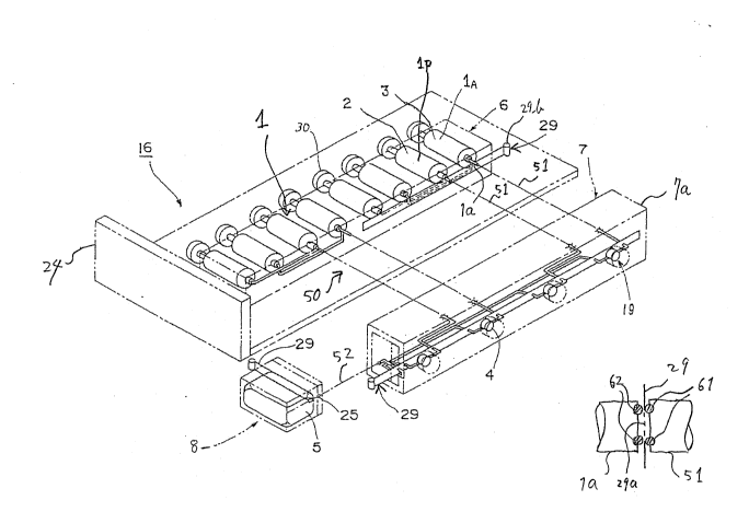
FIG.3(A) shows the perspective view o~ the
essential part of the apparatus according to a first
embodiment of the present invention.
Referring to FIG.3(A), the essential part of
the apparatus forms a cell unit 16 that includes a
plurali-ty of syringes 1 similar to the syringe of FIG.1
for holding protein solutions and/or crystallizing
agents. In the apparatus of FIG.3(A), the syringes 1
are held in a block 6 that in turn is mounted on an
experiment unit 24. As will be described later, the
experiment unit 24 is mounted on a frame 15 that is
fixed on the frame of a space vehicle such as a space
station and forms a part of the frame 15. The syringes
1, on the other hand, are mounded detachably on the
block 6 for repeating the experiment for various mate-
rials. Alternatively, the block 6 itsel~ may be pro-
~ided detachably on the experiment unit 24.
Each syringe l has a piston 30 and an outlet
la closed by a valve mechanism that uses a seal strip
29. The seal strip 29 is held batween a pair of oppos~
ing seal rings 61, 62 as shown in FIG.3(B), wherein the
seal ring 62 is located at the side af the strip 29
corresponding to the opening of the outlet la while the
other seal ring 61 is located at the other side of the
seal strip 29 in corresponding to the opening o~ a tube
51 that forms an interconnection system 50 of theapparatus for supplying the protein solution or the
crystallizing agent. The seal strip 29 is formed with
a number of openings 29a as shown in FIÇ.3(B~, and the
communication between the outlet la and the intercon~
nection system 50 is established or interrupted UpOll
moving a pulling tag 29b formed at the end of the seal
strip 29.
11- 2~ .23
1 In the illustrated example, there are two
types of syringes, lp and lA, wherein the syringes lp
contain the protein solution 2 and the syringes 1A
contain the solution including crystallizing agent 3.
The interconnection system 50 connects the
syringes 1 in the block 6 to a cell block 7 wherein a
plurality of processing chambers 4 are formed. As
shown in FIG.3(A), the communication between the cell
block 7 and the interconnection system 50 is estab-
lished or interrupted by a valve mechanism that uses
the seal strip 29. In the cell block 7j each process~
ing chamber 4 is connected to one or more tubes 51 as
will be described later, and the crystallization of the
protein occurs in the processing chamber 4. In order
to observe the progress of the crystallization, an
observation window 19 is formed in correspondence to
each processing chamber 4. It should be noted that the
cell block 7 is mounted on the body 24 of the cell unit
16 detachably with a predetermined orientation such
that the observation windows 19 are formed on the same
side of the cell block 7 as shown in FIG.3(A).
Further, there is provided a collection block
8 that includes a detachable recovery container 5 in
connection with the processing chambers 4 of the cell
block 7 via a tube 52 for collecting the solution that
is expelled ~rom the processing chamber 4. The commu-
nication between the cell block 7 and the recovery
container 5 is achieved by the tube 52, and there i5
providad a valve mechanism that employs the seal strip
29 described previously with reference to FIG.3(B) for
controlling the communication.
FIG.4 shows the overall construction of the
apparatus of the present invention as assembled in a
frame 15 that is mounted on the frame of the space
vehicle such as a space station.
Referring to FIG.4, the cell blocks 16 are
mounted on the experiment unit 24 that in turn is
- 12 - 2~ 3
1 mounted on the frame 15 like a drawer. It should be
noted that a num~er of such experiment units 24 are
mounted on the frame 15. As shown in FIG.4, the exper-
iment unit 24 is attached slidable on the frame 15 and
is pulled out therefrom by releasing a lock 27. Fur-
ther, at the bottom part of the frame 15, a power unit
25 is provided. The frame 15 includes a panel that
surrounds the space inside the frame 15, and there is
provided a temperature regulation mechanism inside the
space as will be described later.
FIG.5 shows a syringe actuating mechanism 17
mounted on the experiment unit 24 in combination with
the cell unit 16 for actuating the piston 30 of the
syringes 1.
Referring to FIG.5, the syringe actuating
mechanism 17 includes a push plate 31 that engages with
the piston 30, and the push plate 31 is moved in the
direction as shown by the arrows in FIG.5 by a screw 32
that engages with the push plate 31. In order to drive
the screw 32, a stepping motor 33 is provided that
drives tha screw 32 in response to a control signal
supplied thereto from an e~ternal controller (not
shown). By controlling the stepping motor 33, various
e~pariments are possible as will be described later.
; 25 In order to ac-tuate the syrlnges individually, the
actuating mechanism 17 may be provided ~or each of the
syri~ges l. However, it is pre~erable to design the
syringe actuating mechanism 17 such that a plurality o~
selected syringes are activated simultaneously.
In order to control the temperature of exper-
iment, each e~pariment unit 24 carries therein a tem-
perature regulating mechanism 18 that includes a Pelti~
er element 34. The Peltier element 34 contacts with a
heat conductor member 35 provided on the top sur~ace o~
the cell block 7 and controls the temperature inside
the processing chamber 34. In the illustrated example,
therei`ore, the Peltier element 34 contacts-with the
;
- 13 - 2~
1 cell block 7 from the top via the heat conductor member
35. Above the Peltier element, there is provided a
cooling part 36 including a passage 36a of cooling
water, and a thermal insulator 37 is provided to cover
the cell block 7. The enga~ement between the Peltier
element 34 and the heat ronductor member 35 is achieved
when the experiment uni.t 24 is mounted on the frame 15.
This may for example be achieved by raising a body of
the unit 24 upon actuation of the lock 27. As this
mechanism is not essential for the disclosure of the
present invention, and as the designing of such a
mechanism is obvious for the person skilled in the art,
further description will be omitted.
In order to achieve the automatic observation
of the progress of crystallization taking place in the
processing chamber 4, the present invention uses an
automatic observation system described below.
It should be noted in FIG.3 that the vbserva-
tion windows 19 of the processing chamber 4 are formed
on the same side oi the body of the cell unit 7.
FIG.6 shows the automatic observation system.
This system includes a fixed frame or guide rail 41
mounted on the fram2 15 and a movable ~rame 42 that
moves in the vertical direction H by a motor 43 along
the yuide rail 41~ The movable frame 42 in turn iorms
a gulde rail extending in the horizontal dlrection H
and carries an observation unit 20 in the manner mova-
ble in the horizontal dir~ction in response to the
actuation of a motor 43. Thereby, the ob~erv~tion unit
20 is moved in the frame 15 along a vertical plane that
faces the observation windows 19 o~ the processing
chambers 4. In FIG.6, it should be noted that there
are stacked a number of cell blocks 71~ 72~ in
the frame 15 in correspondence to each experiment un.i~
?4. Thus, by providing the automatic observation
system of FIG.6 in correspondence to the center of the
frame 15 of FIG.4, and by providing the observation
- 14 ~ 23
1 unit 20 at the rear side of the movable frame 42, the
observation for the entire processiny chambers 4 in the
frame 15 becomes possible.
FIG.7 shows the construction of the observa-
tion unit 20 of FIG.6.
Referring to FIG.7, the observation unit 20includes a light source 38 of LED and the like for
illuminating the processing chamber 4 and a CCD camera
41 for observing the chamber 4 via the window 19. In
order to direct the light from the chamber 4 to the
camber 41, various optical elements such as a mirror 39
and a lens system 40 may be used. The output of th~
CCD camera 41 may be stored in a memory of a controller
not illustrated.
In the present inventlon, it should be noted
that there is a flexibility in the connection o~ the
syringes 1 in the block 6 to the processing chambers 4
in the cell block 7. By changing the interconnection
system 50, one can achieve various experiments by the
same experimental apparatus. Hereinafter, various
experiments achieved by the apparatus oi FIG.3 will be
described.
FIG.8 shows a second embodiment of the
present invention used for crystallizing the protein
crystals by the batch method. This diagram generally
corresponds to the plan view o~ FIG.3(A). It will be
noted that the block 6 ~or the syringes 1 and the block
7 for the processing chambers 4 are provided ad~acent
with each other, and the syringes 1 are formed in the
block 6.
In this embodiment, the syringes 1 are ar-
ranged to form pairs in ths block 6, and each pair
includes a syringe lp containing the protein solution 2
and a syrinye 1A containing the crystallizing agent
In the present embodiment, the actuating mechanism 17
is designed to actuate a pair of adjacent syringes Ip
and 1~ for the protein solution 2 and the crystallizing
_ 15
1 agent 3 simultaneously. As illustrated, the syringe lp
for the protein solution 2 has an outlet passage 511
extending in the block 6 while the syringe 1~ ~or the
crystallizing agent has an outlet passage 512 also
S extending in the block. These passages 511 and 512 are
connected to merge with each other to form a single
passage 51 that is connected to the processing chamber
4 o~ the cell block 7. It should be noted that the
passages 51, 511, 512 of FIG.8 typically realized by a
flexible tube.
When starting experiment, the syringe block 6
carrying thereon the syringes lA and lp that are filled
with the crystallizing agent and the protein solution
is taken out from the regulated temperature environment
and mounted on the experiment unit 24. In response to
the mounting, the tubes 511 and 522 are connected to
the respective outlets of the syringes lA and lp, and
the seal s$rip 29 is actuated to establish the communi~
cation between the syringes 1 and the processing ch~n-
ber 4. Further, the pro~essing chambers 4 are connect-
ed to the recovery container 5 o~ the block 8 by the
tube 52. Thereby, the cell unit 16 formed from the
block 6, block 7 and the block 8 is ready ~or starting
the experiment.
Upon actuation of the both syring~s lp and
lA, the protein solution 2 and the crystallizing agent
3 are admixed in the tube 51 and transferred to the
processing chamber 4. In response to the transfer o
the mixtura into the chamber 4, the air that has filled
the chamber 4 is expelled and ~ransferred to the recov-
ery container 5 via the tube 52. After the mixture is
thus transferred to the chamber 4, the mixture is held
stationary to cause the crystallization therein.
Generally, complete mixing of the protein solution 2
and the crystallizing agent 3 is not necessary for this
experiment, and a satisfactory mixing is achieved by
simply merging the passages 511 and 512. Of course,
.
- 16 - 2 0 ~ ~1 2 3
1 one may provide a stirrer or other means ~or ensuring
the complete mixing on the -tube 51. On the intermedi-
ate part of the tube 51, one may provide further a
bubble trap 14 to remove the bubhles of air. Such a
bubble trap 14 is easily achieved by a sponge of hydro-
phobic fibers. During the crystallization, the
progress of the process is periodically monitored by
the observation unit 20 as already described.
After the experiment is completed, the seal
st~ip 29 for the cell block 7 is actuated to seal the
chamber 4, and the cell block 7 is dismounted from the
body of the experiment unit 24. The cell block 7
contains the protein crystals in the processing chamber
4 and returned -to the ground. Further, the syringe
block 6 may be dismounted and returned to the ground
similarly.
Next, a third embodiment of the present
invention Eor the free int~rface diffusion method will
be described with reference to FIG.9.
In this embodiment, the construction of the
apparatus is substantially identical with the apparatus
of FIG.8, except for the actuating mechanism 17 that
now actuates the syringes consecutively such that the
2rotein solution 2 is ~irst supplied to the chamber 4
and the crystallizing agent 3 is supplied next or vice
versa. ln order to achieve this actuation sequence,
two of the syringes lA for the crystallizing agent 3
are arranged adjacent each other for the simultaneous
actuation. Similarly, two o~ the syringes ~p for the
protein solution 2 are arranged adjacent each other for
the simultaneous actu~tion.
In response to the consecutive actuation of
the syringe lp and the syringe lA, an inter~ace is
formed in the processing chamber 4 between the protein
solution 2 that is sent thereto previously and the
crystallizing agent 3 that is sent subsequently, and
one can achieve the crystalliza-tion occurs at the
.
- 17 -
1 interface. Thus, this embodiment achieves the free
interface diffusion method.
FIG.10 shows a fourth embodiment o~ the
present invention for achieving the crystallization
according to the gradien~ method. In order to imple-
ment the gradient method, the present embodiment in-
cludes a modificatlon of the structure of the apparatus
of FIG.8. In FIG.10, only the essential part is illus-
trated for the sake of simplicity of the drawing and
explanation. It should be noted tha-t FIG.10 shows the
schematic plan view of the apparatus. See FIG.3 for
comparison.
In the present embodiment, the syringes lp
; and lA are formed in the block 6 for holding the pro-
tein solution 2 and the crystallizing agent 3 separate-
ly. Further, the tubes 511 and 512 are connected to
the block 6. Similar to the embodiment of FIG.~, the
tubes 511 and 512 merge with each other to form the
single passage 51 that is connected to the processing
chamber 4 in the cell block 7 by a flexible tube 51~o
The processing chamber 4 is ~urther connected to the
recovery container 5 via the passage 52 that is also
realized by a flexible tube.
In the intermediate location of the passage
511, there is provided a container 10 ~or holding a
crystallizing agent 3' haviny a concentration dif~erent
from the crystallizing agent 3 in the syringe 1. In
the container 10, there is provided a stirrer lOa or
causing stirring.
Thus, upon actuation of the syringe 1, the
content of the container 3' is supplied first to the
processing chamber 4 together with the protein solution
2. With continuous actuation, the agent 3 in the
syringe starts to be fed to the container 10 where c.he
agent 3 is mixed with the agent 3' held therein. Thus,
the concentration of the crystallizing agent mixture
that is fed to the processing chamber 4 via the passage
- 18 ~ ?J3
1 51 and the tube 51' changes with time.
Such a variation of the concentration of the
crystallizing agent mixture with time in turn induces a
gradient in the concentration of the crystallizing
agent in the processing chamber 4 as the crystallizing
agent mixture is fed to the chamber 4 together with the
protein solution 2 gradually. In the present inven-
tion, the processing chamber 4 is thereby pro~ided with
a device for fixing the concentration gradient of the
crystallizing agent in the chamber 4 for realizing
various crystallizing conditions.
FIG.11 shows the processing chamber 4 that is
provided with a device 44 for fixing the concentration
gradient.
Referring to FIG.ll, the processing chamber 4
of the present embodiment is formed from a transparent,
flexible tube, and the device 44 is formed from a pair
of opposing comb-shaped elements 44a and 44b each
having a number of teeth 45. Upon actuation of the
device 44, the opposing elements 44a and 44b are
pressed with each other such that each opposing tooth
45 engages with each other. Thereby, the flexible tube
forming the processing chamber 4 is divided into a
number of cells each characterized by a particular
concentration level of the crystallizing aqent mixture.
By leaving the chamber 4 for a predetermined duration
while maintaining this state, one can achieve the
crystallization of the protein crystals simultaneously
in the respective cells at various conditions.
FIG.11 further shows the valves realized ~y
the seal strip 29. Before the start of the experiment,
the seal strip 29 interrupts the communication between
respective parts of the block 6 to seal the syringes 1
in the block. Upon commencement of the experiment, the
seal strip 29 is actuated to establish the communica-
tion, and the foregoing faeding of the protein solutio
2 and the crystallizing agents 3 and 3' to the process-
. .
- 19- 2~ 23
1 ing chamber 4 is achieved in response to the actuation
of the syringes. A*ter the crys-tallization is complet-
ed, both ends of the flexible tube forming the process-
ing chamber 4 is closed by a pinch cock 29' or the
like, and the processing chamber 4 is removed for
transportation to the ground. During this transporta-
tion, the device 44 is held in the activated state such
th~t the communication between the cells in the chamber
4 is interrupted.
FIG.12 shows a fifth embodiment of the
present invention.
In the present embodiment, the apparatus has
a structure similar to FIG.8 except that the protein
solution 2 is held in the processing chamber 4 and
sealed therein by a dialysis membrane 11. As shown in
FIG.12, the protein solution is held in an inner cham~
ber 4a defined in the chamber 4 by the membrana 11.
Thereby, the entire syringes 1 are used to hold the
crystallizing agent. In the present embodiment, two
crystallizing agents 3 and 3' having diffsrent concen-
tration levels are used for the e~periment. Thereby,
there are formed two types of syringes, a syringe lA
for the agent 3 and a syringe lA' for the agent 3',
both in the block 6, wherein all the syringes are
connected commonly to the passage 51 tha~ extends to an
outer chamber 4b defined in the processing chamber 4.
The outer chamber 4b i 5 separated from the inner cham-
ber 4a by the dialysis membrane 11.
In the experiment, the block 6 is taken out
from the regulated environment and mounted on the
experiment unit 24 in connection with the cell block 7
that carries the processing chamber 4. After estab-
lishing the communication of the passage 51 with the
syringes 1 as well as the processing chamber 5 by
actuating the seal strip 29, the syringes lA for the
crystallizing agent 3 is activated. In response there~
to, the agent 3 of the lower concentration level is fed
2 ~ 2 ~
1 to the outer chamber 4b of the processing chamber 4 for
cleaning the passage wall of the passage 51. Next, the
syringe lA' is actuated to feed the crystallizing agent
3' of higher concentration level to the outer chamber
4b. The agent 3' that have filled the outer chamber 4
is expelled to the recovery container 5. Thereby, the
crys~allizing agent 3' contacts with the protein solu-
tion 2 via the dialysis mambrane 11 and causes the
oversaturation in the protein solution 2 held in the
inner chamber 4a. After the crystallization achieved,
the processing chamber 4 is sealed by the seal strip 29
and the cell block 7 removed for transportation back to
the ground.
FIG.13 shows an enlarged, yet schematic view
showing the principle of the appara-tus of FIG.12. For
the sake of simplicity, only a pair of syringes lA and
lA' are shown. As shown in FIG.13, the syringes lA and
lA' are connected to the outer chamber 4b of the proc-
essing chamber 4 by the passage 51, and the outer
ZO chamber 4b is further connacted to the recovery con-
tainer 5 via the passage 52. The recovery container 5
further has a vent for releasing the air in -the chamber
4b. The crystallizing agents 3 and 3' are fed to the
outer chamber 4b as already described and the crystal-
lization occurs in the protein solution 2 in the innerchamber 4a as a result of the transport of materials
through the dialysis membrane 11. For example, the
water in the solution 2 may be transported to the
crystallizing agent 3 via the membrane 11 and the
oversaturation condition appears in the solution 2.
FIG.14 shows a sixth embodiment of the
present in~ention for implementing the crystallization
of protein according to the vapor diffusion method.
In this embodiment, the processing chamber 4
is formed from the inner chamber 4a and the outer
chamber 4b similar to the previous embodiment, wherein
the inner chamber 4a is supplied with the protein
- 21 -
1 solution 2 from the syringe lp and the outer chamber 4b
is supplied with the crystallizing agent 3 ~rom the
syringe 1~. The difference oi the present embodiment
over the previous one in the designing of the process-
ing chamber 4 exists in the point that the inner cham-
ber 4a and the outer ch~mber 4b are communication with
each other rather than separated by the membrane 11 as
in the previous embodiment. Thus, the distinction
between the inner chamber 4a and the outer chamber 4b
is somewhat arbitrary except that they are formed at
opposing ends o~ the processing chamber 4. Other part
of the apparatus is substantially identical with the
apparatus of FI~.8.
FIG.15 shows a schematical illustration o~
the essential part of the apparatus of FIG.14 in the
enlarged scale. For the sake of clarity of the illus-
tration, only a pair of the syringes lp and lA are
shown.
As shown in FIG.15, the protein solution 2 in
the syringe lp is fed to the inner chamber 4a of the
processing chamber, while the crystallizing agent 3 in
the syringe lA is supplied to a liquid-retaining ele-
ment 13 such as a sponge that is held in the outer
chamber 4b o~ the proc~ssing chambsr 4. Thereby, the
direct con~act of the protein solution 2 and the crys~
tallizing agent 3 i5 prevented. The crystallization
occurs in the protein solution as a result ~f the
transport of materials between the solution 2 and tha
agent 3 in the form of vapor.
FIG.16 shows a modification of the apparatus
of FIG.14, wherein the protein solution 2 is sealed in
ths inner chamber 4a of the processing chamber 4 by the
seal realized by the seal strip 29 as described previ-
ously. After mounting the cell block 7 on the experi~
ment unit 24, the seal is broken by actuating the seal
strip 29. Further, the syringes 1~ for holding the
crystallizing agent 3 are activated and the crys~alliz~
~ 22 ~ ?~3
1 ing agent 3 is transferred to the liquid retaining
element 13. There, the crystallization o the protein
crystal is achieved in the solution 2 according to the
vapor diffusion method similar to the embodiment of
FIG.14.
As described heretofore, the present inven-
tion enables various experiments by aesigning the
interconnection part 50 variously. The passage 51 that
forms the interconnection part 50 may either b~ a tube
- 10 as described previously or a passage that is provided
within thP blocks 6 and 7 of a solid material.
Further, the present invention is not limited
to the embodiments described heretofore, but various
variations and modifications may be made without de
parting from the scope of the invention.