Language selection

Search

Patent 2054365 Summary

Third-party information liability

Some of the information on this Web page has been provided by external sources. The Government of Canada is not responsible for the accuracy, reliability or currency of the information supplied by external sources. Users wishing to rely upon this information should consult directly with the source of the information. Content provided by external sources is not subject to official languages, privacy and accessibility requirements.

Claims and Abstract availability

Any discrepancies in the text and image of the Claims and Abstract are due to differing posting times. Text of the Claims and Abstract are posted:

  • At the time the application is open to public inspection;
  • At the time of issue of the patent (grant).
(12) Patent: (11) CA 2054365
(54) English Title: TUNABLE MICROSTRIP BANDPASS FILTER
(54) French Title: FILTRE PASSE-BANDE ACCORDABLE A MICRORUBANS
Status: Expired and beyond the Period of Reversal
Bibliographic Data
(51) International Patent Classification (IPC):
  • H01P 01/20 (2006.01)
  • H01P 01/217 (2006.01)
  • H01P 01/218 (2006.01)
(72) Inventors :
  • RACHLIN, ADAM (United States of America)
  • WANDINGER, LOTHAR (United States of America)
  • BABBITT, RICHARD W. (United States of America)
(73) Owners :
  • GOVERNMENT OF THE UNITED STATES, AS REPRESENTED BY THE SECRETARY OF THE ARMY (THE)
(71) Applicants :
  • GOVERNMENT OF THE UNITED STATES, AS REPRESENTED BY THE SECRETARY OF THE ARMY (THE) (United States of America)
(74) Agent: KALEVI P. ASPILAASPILA, KALEVI P.
(74) Associate agent:
(45) Issued: 1998-09-29
(22) Filed Date: 1991-10-28
(41) Open to Public Inspection: 1992-07-05
Examination requested: 1993-11-17
Availability of licence: N/A
Dedicated to the Public: N/A
(25) Language of filing: English

Patent Cooperation Treaty (PCT): No

(30) Application Priority Data:
Application No. Country/Territory Date
07/637,426 (United States of America) 1991-01-04

Abstracts

English Abstract


A tunable bandpass filter comprises a flat
ferrite body having first and second spaced,
coextensive microstrip conductive lines on its upper
surface. A winding encircles the ferrite and
conductive lines so that a variable d-c current in the
winding varies the magnetic permeability of the ferrite
and thus the center frequency of the filter.


French Abstract

Filtre passe-bande accordable comportant un corps plat en ferrite qui a sur sa surface supérieure des première et deuxième lignes conductrices microruban espacées coextensives. Un enroulement entoure le ferrite et les lignes conductrices, de sorte qu'un courant continu variable dans l'enroulement fait varier la perméabilité magnétique du ferrite et conséquemment la fréquence centrale du filtre.

Claims

Note: Claims are shown in the official language in which they were submitted.

THE EMBODIMENTS OF THE INVENTION IN WHICH AN EXCLUSIVE PROPERTY
OR PRIVILEGE IS CLAIMED ARE DEFINED AS FOLLOWS:
1. A tunable bandpass filter comprising:
a dielectric substrate;
a magnetically permeable body having at least two
tapered ends and a direction of extension between the tapered
ends, the magnetically permeable body being attached to the
dielectric substrate and covering only a portion of the
dielectric substrate;
a plurality of microstrip lines wherein the microstrip
lines are spaced from one another and fixed to said magnetically
permeable body, the microstrip lines extending from the tapered
ends of the magnetically permeable body and on to the dielectric
substrate; and
a current carrying winding having an axis and being
wound around at least portions of said magnetically permeable
body and said microstrip lines.
2. The tunable filter of Claim 1, wherein the axis of said
winding is generally parallel to the direction of extension of
said magnetically permeable body.
3. The tunable filter of Claim 1, wherein said
magnetically permeable body is a ferrite substrate.

4. The tunable filter of Claim 1, wherein the dielectric
substrate has at least first and second parallel slots
therethrough; said winding extending through said first and
second slots in said dielectric substrate; said first and second
slots extending along adjacent sides of said magnetically
permeable body and parallel to the axis of said winding.

Description

Note: Descriptions are shown in the official language in which they were submitted.


2054365
This invention relates to microwave
bandpass filters and more specifically relates to a
tunable microstrip bandpass filter.
Microwave bandpass filters are two port
devices which allow the reception of a predetermined
band of frequencies and suppress all other frequencies,
An ideal filter will accept frequencies within a
frequency range which precisely matches the band width
and center frequency of the communication spectrum
desired. Within that ranqe, it will pass signals with
almost no dissipation or distortion.
Current parallel coupled microstrip
bandpass filters have a fixed center frequency. They
employ spaced parallel coupled microstrip lines printed
on a planar dielectric. Thus their structure is simple
and inexpensive. However, these and other bandpass
filters operating above lGHz have only a fixed center
frequency and bandwidth.
A tunable filter has an electronically
adjustable center frequency which, when used correctly,
will operate within a linear frequency range.
Tunability allows the filter to be adjusted to the
center frequency of the signal to be received and also
allows reception of multiple signals in a multiplexing
scheme and is usable in a number of microwave
applications.
--1--

205~36~
The invention provides a means to adjust
(e.g. selectively modify) the magnetic permeability of
the ferrite of a microstrip band pass filter to permit
the filter to be tunable over a limited linear range of
center frequencies. Preferably, the adjustment means
comprises a winding which encircles the parallel
coupled microstrip lines and the underlying ferrite. A
d/c current applied to the winding produces a biasing
magnetic field along the long axis of the filter which
changes the magnetic permeability of the ferrite, and
thus the center frequency of the filter. The d/c
current can be controlled in any desired manner, either
manually or electronically, in response to the behavior
of some other control circuit for the purpose of
adjusting the center frequency of the filter.
More specifically, the permeability (u') of
the ferrite changes when a magnetic biasing field is
applied. This change in permeability results in a
change in the velocity of standing waves (Vp) between
coupled microstrip pairs, according to the relationship
Vp=c~u'rer. This change in standing wave velocity
results in a change in the frequency of the standing
wave, f=Vp/2~.

205~365
Magnetic biasing is preferably produced by
winding a copper coil around the ferrite microstrip and
applying a d-c current to the coil. The induced
magnetic field within the coil and ferrite changes the
permeability (u') of the ferrite. By varying the coil
current, one can either increase or decrease the
permeability of the ferrite, thus changing the standing
wave velocity (Vp) and hence the frequency, (f=Vp/2~).
This makes it possible to tune the center frequency of
a bandpass filter.
Such a tunable microstrip filter is low in
cost and can easily be fabricated using existing
technology.
These and other objects, features, and
details of the invention will become apparent in light
of the ensuing detailed disclosure, and particularly in
light of the drawings wherein:
Fig. 1 is a perspective schematic view of a
microstrip bandpass filter.
Fig. 2 is a drawing similar to Fig. 1 but
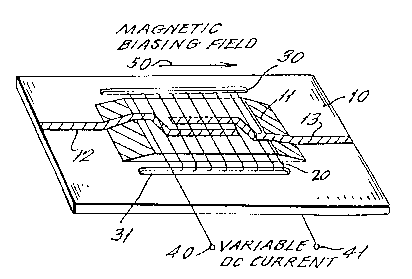
shows the addition of a ferrite substrate and a d/c
bias for varying the permeability of the ferrite to
enable tuning of the filter.

2 0 5 4 3 6 5
Fig. 1 shows a fixed frequency microstrip
filter. This filter is fabricated by printing
continuous parallel coupled microstrip lines 12 and 13
upon a dielectric substrate 10. This dielectric
substrate 10 is most commonly aluminum (ET~9.9) or
Duroid (ET_2.2) which is the name of a trademarked
material. As noted previously, an ideal filter of this
type only accepts frequencies within a specific
frequency range which precisely matches the desired
lo band width and a fixed center frequency of the
communication spectrum.
In accordance with the present invention,
and as shown in Fig. 2, a thin tapered ferrite
substrate 11 is secured to the dielectric substrate 10.
The ferrite substrate may be attached to the dielectric
substrate by a conductive epoxy. Continuous parallel
coupled microstrip lines 12 and 13 are printed upon
both the dielectric substrate 10 and the ferrite
substrate 11. A multiturn copper winding or coil 20
extends around the ferrite substrate 11 and microstrip
lines 12 and 13 and extends through slots 30 and 31 in
support 10. The terminals 40 and 41 of winding 20 are
connected to a source of variable d/c current, as
labeled. The production of a d/c current in coil 20
produces a magnetic biasing field 50 within the
ferrite. As described above, the induced magnetic
r~ ~
~ 4-

20S~365
biasing field 50 changes the magnetic permeability of
the ferrite, and thus the center frequency of the
filter may be manipulated due to the resultant change
in the velocity of the standing waves between the
coupled microstrip lines 12 and 13.
Any desired structure can be employed to
generate the magnetic biasing field, for example,
permanent magnets or electromagnets which are separate
from or integrated with ~he ferrite 11 can be used.
Furthermore, the invention is applicable to microwave
devices having different orientations of microstrip
lines and ferrite than that shown in Figs. 1 and 2.
Although the present invention has been
described in relation to a particular embodiment
thereof, many other variations and modifications and
other uses will become apparent to those skilled in the
art. It is preferred, therefore, that the present
invention be limited not by the specific disclosure
herein, but only by the appended claims.

Representative Drawing
A single figure which represents the drawing illustrating the invention.
Administrative Status

2024-08-01:As part of the Next Generation Patents (NGP) transition, the Canadian Patents Database (CPD) now contains a more detailed Event History, which replicates the Event Log of our new back-office solution.

Please note that "Inactive:" events refers to events no longer in use in our new back-office solution.

For a clearer understanding of the status of the application/patent presented on this page, the site Disclaimer , as well as the definitions for Patent , Event History , Maintenance Fee  and Payment History  should be consulted.

Event History

Description Date
Inactive: IPC from MCD 2006-03-11
Time Limit for Reversal Expired 2000-10-30
Letter Sent 1999-10-28
Grant by Issuance 1998-09-29
Inactive: Final fee received 1998-05-26
Pre-grant 1998-05-26
Letter Sent 1998-05-04
Notice of Allowance is Issued 1998-05-04
Inactive: Application prosecuted on TS as of Log entry date 1998-04-27
Inactive: Status info is complete as of Log entry date 1998-04-27
Inactive: IPC assigned 1998-04-22
Inactive: First IPC assigned 1998-04-22
Inactive: IPC removed 1998-04-22
Inactive: IPC removed 1998-01-26
Inactive: IPC assigned 1998-01-26
Inactive: First IPC assigned 1998-01-26
Inactive: IPC assigned 1998-01-26
Inactive: Approved for allowance (AFA) 1997-12-29
All Requirements for Examination Determined Compliant 1993-11-17
Request for Examination Requirements Determined Compliant 1993-11-17
Application Published (Open to Public Inspection) 1992-07-05

Abandonment History

There is no abandonment history.

Maintenance Fee

The last payment was received on 1997-09-16

Note : If the full payment has not been received on or before the date indicated, a further fee may be required which may be one of the following

  • the reinstatement fee;
  • the late payment fee; or
  • additional fee to reverse deemed expiry.

Patent fees are adjusted on the 1st of January every year. The amounts above are the current amounts if received by December 31 of the current year.
Please refer to the CIPO Patent Fees web page to see all current fee amounts.

Fee History

Fee Type Anniversary Year Due Date Paid Date
MF (application, 6th anniv.) - standard 06 1997-10-28 1997-09-16
Final fee - standard 1998-05-26
MF (patent, 7th anniv.) - standard 1998-10-28 1998-09-28
Owners on Record

Note: Records showing the ownership history in alphabetical order.

Current Owners on Record
GOVERNMENT OF THE UNITED STATES, AS REPRESENTED BY THE SECRETARY OF THE ARMY (THE)
Past Owners on Record
ADAM RACHLIN
LOTHAR WANDINGER
RICHARD W. BABBITT
Past Owners that do not appear in the "Owners on Record" listing will appear in other documentation within the application.
Documents

To view selected files, please enter reCAPTCHA code :


To view images, click a link in the Document Description column. To download the documents, select one or more checkboxes in the first column and then click the "Download Selected in PDF format (Zip Archive)" or the "Download Selected as Single PDF" button.

List of published and non-published patent-specific documents on the CPD .

If you have any difficulty accessing content, you can call the Client Service Centre at 1-866-997-1936 or send them an e-mail at CIPO Client Service Centre.


Document
Description 
Date
(yyyy-mm-dd) 
Number of pages   Size of Image (KB) 
Description 1993-12-14 5 146
Claims 1993-12-14 4 104
Abstract 1993-12-14 1 11
Drawings 1993-12-14 1 31
Drawings 1997-12-09 1 24
Description 1997-12-09 5 148
Claims 1997-12-09 2 39
Representative drawing 1998-09-02 1 13
Commissioner's Notice - Application Found Allowable 1998-05-03 1 164
Maintenance Fee Notice 1999-11-24 1 179
Fees 1998-09-27 1 43
Correspondence 1998-05-25 2 73
Fees 1997-09-15 1 49
Fees 1996-07-29 2 222
Fees 1995-09-10 2 230
Fees 1994-08-25 2 130
Fees 1993-09-22 2 119
Prosecution correspondence 1993-11-16 1 35
Prosecution correspondence 1993-11-17 2 52
Examiner Requisition 1997-07-20 2 44
Prosecution correspondence 1997-10-13 5 175
Courtesy - Office Letter 1994-01-26 1 54
Courtesy - Office Letter 1992-06-01 1 59
Courtesy - Office Letter 1992-05-25 1 53