Sélection de la langue

Search

Sommaire du brevet 2054365 

Énoncé de désistement de responsabilité concernant l'information provenant de tiers

Une partie des informations de ce site Web a été fournie par des sources externes. Le gouvernement du Canada n'assume aucune responsabilité concernant la précision, l'actualité ou la fiabilité des informations fournies par les sources externes. Les utilisateurs qui désirent employer cette information devraient consulter directement la source des informations. Le contenu fourni par les sources externes n'est pas assujetti aux exigences sur les langues officielles, la protection des renseignements personnels et l'accessibilité.

Disponibilité de l'Abrégé et des Revendications

L'apparition de différences dans le texte et l'image des Revendications et de l'Abrégé dépend du moment auquel le document est publié. Les textes des Revendications et de l'Abrégé sont affichés :

  • lorsque la demande peut être examinée par le public;
  • lorsque le brevet est émis (délivrance).
(12) Brevet: (11) CA 2054365
(54) Titre français: FILTRE PASSE-BANDE ACCORDABLE A MICRORUBANS
(54) Titre anglais: TUNABLE MICROSTRIP BANDPASS FILTER
Statut: Périmé et au-delà du délai pour l’annulation
Données bibliographiques
(51) Classification internationale des brevets (CIB):
  • H01P 01/20 (2006.01)
  • H01P 01/217 (2006.01)
  • H01P 01/218 (2006.01)
(72) Inventeurs :
  • RACHLIN, ADAM (Etats-Unis d'Amérique)
  • WANDINGER, LOTHAR (Etats-Unis d'Amérique)
  • BABBITT, RICHARD W. (Etats-Unis d'Amérique)
(73) Titulaires :
  • GOVERNMENT OF THE UNITED STATES, AS REPRESENTED BY THE SECRETARY OF THE ARMY (THE)
(71) Demandeurs :
  • GOVERNMENT OF THE UNITED STATES, AS REPRESENTED BY THE SECRETARY OF THE ARMY (THE) (Etats-Unis d'Amérique)
(74) Agent: KALEVI P. ASPILAASPILA, KALEVI P.
(74) Co-agent:
(45) Délivré: 1998-09-29
(22) Date de dépôt: 1991-10-28
(41) Mise à la disponibilité du public: 1992-07-05
Requête d'examen: 1993-11-17
Licence disponible: S.O.
Cédé au domaine public: S.O.
(25) Langue des documents déposés: Anglais

Traité de coopération en matière de brevets (PCT): Non

(30) Données de priorité de la demande:
Numéro de la demande Pays / territoire Date
07/637,426 (Etats-Unis d'Amérique) 1991-01-04

Abrégés

Abrégé français

Filtre passe-bande accordable comportant un corps plat en ferrite qui a sur sa surface supérieure des première et deuxième lignes conductrices microruban espacées coextensives. Un enroulement entoure le ferrite et les lignes conductrices, de sorte qu'un courant continu variable dans l'enroulement fait varier la perméabilité magnétique du ferrite et conséquemment la fréquence centrale du filtre.


Abrégé anglais


A tunable bandpass filter comprises a flat
ferrite body having first and second spaced,
coextensive microstrip conductive lines on its upper
surface. A winding encircles the ferrite and
conductive lines so that a variable d-c current in the
winding varies the magnetic permeability of the ferrite
and thus the center frequency of the filter.

Revendications

Note : Les revendications sont présentées dans la langue officielle dans laquelle elles ont été soumises.


THE EMBODIMENTS OF THE INVENTION IN WHICH AN EXCLUSIVE PROPERTY
OR PRIVILEGE IS CLAIMED ARE DEFINED AS FOLLOWS:
1. A tunable bandpass filter comprising:
a dielectric substrate;
a magnetically permeable body having at least two
tapered ends and a direction of extension between the tapered
ends, the magnetically permeable body being attached to the
dielectric substrate and covering only a portion of the
dielectric substrate;
a plurality of microstrip lines wherein the microstrip
lines are spaced from one another and fixed to said magnetically
permeable body, the microstrip lines extending from the tapered
ends of the magnetically permeable body and on to the dielectric
substrate; and
a current carrying winding having an axis and being
wound around at least portions of said magnetically permeable
body and said microstrip lines.
2. The tunable filter of Claim 1, wherein the axis of said
winding is generally parallel to the direction of extension of
said magnetically permeable body.
3. The tunable filter of Claim 1, wherein said
magnetically permeable body is a ferrite substrate.

4. The tunable filter of Claim 1, wherein the dielectric
substrate has at least first and second parallel slots
therethrough; said winding extending through said first and
second slots in said dielectric substrate; said first and second
slots extending along adjacent sides of said magnetically
permeable body and parallel to the axis of said winding.

Description

Note : Les descriptions sont présentées dans la langue officielle dans laquelle elles ont été soumises.

2054365
This invention relates to microwave
bandpass filters and more specifically relates to a
tunable microstrip bandpass filter.
Microwave bandpass filters are two port
devices which allow the reception of a predetermined
band of frequencies and suppress all other frequencies,
An ideal filter will accept frequencies within a
frequency range which precisely matches the band width
and center frequency of the communication spectrum
desired. Within that ranqe, it will pass signals with
almost no dissipation or distortion.
Current parallel coupled microstrip
bandpass filters have a fixed center frequency. They
employ spaced parallel coupled microstrip lines printed
on a planar dielectric. Thus their structure is simple
and inexpensive. However, these and other bandpass
filters operating above lGHz have only a fixed center
frequency and bandwidth.
A tunable filter has an electronically
adjustable center frequency which, when used correctly,
will operate within a linear frequency range.
Tunability allows the filter to be adjusted to the
center frequency of the signal to be received and also
allows reception of multiple signals in a multiplexing
scheme and is usable in a number of microwave
applications.
--1--

205~36~
The invention provides a means to adjust
(e.g. selectively modify) the magnetic permeability of
the ferrite of a microstrip band pass filter to permit
the filter to be tunable over a limited linear range of
center frequencies. Preferably, the adjustment means
comprises a winding which encircles the parallel
coupled microstrip lines and the underlying ferrite. A
d/c current applied to the winding produces a biasing
magnetic field along the long axis of the filter which
changes the magnetic permeability of the ferrite, and
thus the center frequency of the filter. The d/c
current can be controlled in any desired manner, either
manually or electronically, in response to the behavior
of some other control circuit for the purpose of
adjusting the center frequency of the filter.
More specifically, the permeability (u') of
the ferrite changes when a magnetic biasing field is
applied. This change in permeability results in a
change in the velocity of standing waves (Vp) between
coupled microstrip pairs, according to the relationship
Vp=c~u'rer. This change in standing wave velocity
results in a change in the frequency of the standing
wave, f=Vp/2~.

205~365
Magnetic biasing is preferably produced by
winding a copper coil around the ferrite microstrip and
applying a d-c current to the coil. The induced
magnetic field within the coil and ferrite changes the
permeability (u') of the ferrite. By varying the coil
current, one can either increase or decrease the
permeability of the ferrite, thus changing the standing
wave velocity (Vp) and hence the frequency, (f=Vp/2~).
This makes it possible to tune the center frequency of
a bandpass filter.
Such a tunable microstrip filter is low in
cost and can easily be fabricated using existing
technology.
These and other objects, features, and
details of the invention will become apparent in light
of the ensuing detailed disclosure, and particularly in
light of the drawings wherein:
Fig. 1 is a perspective schematic view of a
microstrip bandpass filter.
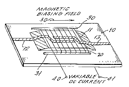
Fig. 2 is a drawing similar to Fig. 1 but
shows the addition of a ferrite substrate and a d/c
bias for varying the permeability of the ferrite to
enable tuning of the filter.

2 0 5 4 3 6 5
Fig. 1 shows a fixed frequency microstrip
filter. This filter is fabricated by printing
continuous parallel coupled microstrip lines 12 and 13
upon a dielectric substrate 10. This dielectric
substrate 10 is most commonly aluminum (ET~9.9) or
Duroid (ET_2.2) which is the name of a trademarked
material. As noted previously, an ideal filter of this
type only accepts frequencies within a specific
frequency range which precisely matches the desired
lo band width and a fixed center frequency of the
communication spectrum.
In accordance with the present invention,
and as shown in Fig. 2, a thin tapered ferrite
substrate 11 is secured to the dielectric substrate 10.
The ferrite substrate may be attached to the dielectric
substrate by a conductive epoxy. Continuous parallel
coupled microstrip lines 12 and 13 are printed upon
both the dielectric substrate 10 and the ferrite
substrate 11. A multiturn copper winding or coil 20
extends around the ferrite substrate 11 and microstrip
lines 12 and 13 and extends through slots 30 and 31 in
support 10. The terminals 40 and 41 of winding 20 are
connected to a source of variable d/c current, as
labeled. The production of a d/c current in coil 20
produces a magnetic biasing field 50 within the
ferrite. As described above, the induced magnetic
r~ ~
~ 4-

20S~365
biasing field 50 changes the magnetic permeability of
the ferrite, and thus the center frequency of the
filter may be manipulated due to the resultant change
in the velocity of the standing waves between the
coupled microstrip lines 12 and 13.
Any desired structure can be employed to
generate the magnetic biasing field, for example,
permanent magnets or electromagnets which are separate
from or integrated with ~he ferrite 11 can be used.
Furthermore, the invention is applicable to microwave
devices having different orientations of microstrip
lines and ferrite than that shown in Figs. 1 and 2.
Although the present invention has been
described in relation to a particular embodiment
thereof, many other variations and modifications and
other uses will become apparent to those skilled in the
art. It is preferred, therefore, that the present
invention be limited not by the specific disclosure
herein, but only by the appended claims.

Dessin représentatif
Une figure unique qui représente un dessin illustrant l'invention.
États administratifs

2024-08-01 : Dans le cadre de la transition vers les Brevets de nouvelle génération (BNG), la base de données sur les brevets canadiens (BDBC) contient désormais un Historique d'événement plus détaillé, qui reproduit le Journal des événements de notre nouvelle solution interne.

Veuillez noter que les événements débutant par « Inactive : » se réfèrent à des événements qui ne sont plus utilisés dans notre nouvelle solution interne.

Pour une meilleure compréhension de l'état de la demande ou brevet qui figure sur cette page, la rubrique Mise en garde , et les descriptions de Brevet , Historique d'événement , Taxes périodiques et Historique des paiements devraient être consultées.

Historique d'événement

Description Date
Inactive : CIB de MCD 2006-03-11
Le délai pour l'annulation est expiré 2000-10-30
Lettre envoyée 1999-10-28
Accordé par délivrance 1998-09-29
Inactive : Taxe finale reçue 1998-05-26
Préoctroi 1998-05-26
Lettre envoyée 1998-05-04
Un avis d'acceptation est envoyé 1998-05-04
Inactive : Dem. traitée sur TS dès date d'ent. journal 1998-04-27
Inactive : Renseign. sur l'état - Complets dès date d'ent. journ. 1998-04-27
Inactive : CIB attribuée 1998-04-22
Inactive : CIB en 1re position 1998-04-22
Inactive : CIB enlevée 1998-04-22
Inactive : CIB enlevée 1998-01-26
Inactive : CIB attribuée 1998-01-26
Inactive : CIB en 1re position 1998-01-26
Inactive : CIB attribuée 1998-01-26
Inactive : Approuvée aux fins d'acceptation (AFA) 1997-12-29
Toutes les exigences pour l'examen - jugée conforme 1993-11-17
Exigences pour une requête d'examen - jugée conforme 1993-11-17
Demande publiée (accessible au public) 1992-07-05

Historique d'abandonnement

Il n'y a pas d'historique d'abandonnement

Taxes périodiques

Le dernier paiement a été reçu le 1997-09-16

Avis : Si le paiement en totalité n'a pas été reçu au plus tard à la date indiquée, une taxe supplémentaire peut être imposée, soit une des taxes suivantes :

  • taxe de rétablissement ;
  • taxe pour paiement en souffrance ; ou
  • taxe additionnelle pour le renversement d'une péremption réputée.

Les taxes sur les brevets sont ajustées au 1er janvier de chaque année. Les montants ci-dessus sont les montants actuels s'ils sont reçus au plus tard le 31 décembre de l'année en cours.
Veuillez vous référer à la page web des taxes sur les brevets de l'OPIC pour voir tous les montants actuels des taxes.

Historique des taxes

Type de taxes Anniversaire Échéance Date payée
TM (demande, 6e anniv.) - générale 06 1997-10-28 1997-09-16
Taxe finale - générale 1998-05-26
TM (brevet, 7e anniv.) - générale 1998-10-28 1998-09-28
Titulaires au dossier

Les titulaires actuels et antérieures au dossier sont affichés en ordre alphabétique.

Titulaires actuels au dossier
GOVERNMENT OF THE UNITED STATES, AS REPRESENTED BY THE SECRETARY OF THE ARMY (THE)
Titulaires antérieures au dossier
ADAM RACHLIN
LOTHAR WANDINGER
RICHARD W. BABBITT
Les propriétaires antérieurs qui ne figurent pas dans la liste des « Propriétaires au dossier » apparaîtront dans d'autres documents au dossier.
Documents

Pour visionner les fichiers sélectionnés, entrer le code reCAPTCHA :


Pour visualiser une image, cliquer sur un lien dans la colonne description du document. Pour télécharger l'image (les images), cliquer l'une ou plusieurs cases à cocher dans la première colonne et ensuite cliquer sur le bouton "Télécharger sélection en format PDF (archive Zip)" ou le bouton "Télécharger sélection (en un fichier PDF fusionné)".

Liste des documents de brevet publiés et non publiés sur la BDBC .

Si vous avez des difficultés à accéder au contenu, veuillez communiquer avec le Centre de services à la clientèle au 1-866-997-1936, ou envoyer un courriel au Centre de service à la clientèle de l'OPIC.


Description du
Document 
Date
(aaaa-mm-jj) 
Nombre de pages   Taille de l'image (Ko) 
Description 1993-12-14 5 146
Revendications 1993-12-14 4 104
Abrégé 1993-12-14 1 11
Dessins 1993-12-14 1 31
Dessins 1997-12-09 1 24
Description 1997-12-09 5 148
Revendications 1997-12-09 2 39
Dessin représentatif 1998-09-02 1 13
Avis du commissaire - Demande jugée acceptable 1998-05-03 1 164
Avis concernant la taxe de maintien 1999-11-24 1 179
Taxes 1998-09-27 1 43
Correspondance 1998-05-25 2 73
Taxes 1997-09-15 1 49
Taxes 1996-07-29 2 222
Taxes 1995-09-10 2 230
Taxes 1994-08-25 2 130
Taxes 1993-09-22 2 119
Correspondance de la poursuite 1993-11-16 1 35
Correspondance de la poursuite 1993-11-17 2 52
Demande de l'examinateur 1997-07-20 2 44
Correspondance de la poursuite 1997-10-13 5 175
Courtoisie - Lettre du bureau 1994-01-26 1 54
Courtoisie - Lettre du bureau 1992-06-01 1 59
Courtoisie - Lettre du bureau 1992-05-25 1 53