Language selection

Search

Patent 2054367 Summary

Third-party information liability

Some of the information on this Web page has been provided by external sources. The Government of Canada is not responsible for the accuracy, reliability or currency of the information supplied by external sources. Users wishing to rely upon this information should consult directly with the source of the information. Content provided by external sources is not subject to official languages, privacy and accessibility requirements.

Claims and Abstract availability

Any discrepancies in the text and image of the Claims and Abstract are due to differing posting times. Text of the Claims and Abstract are posted:

  • At the time the application is open to public inspection;
  • At the time of issue of the patent (grant).
(12) Patent: (11) CA 2054367
(54) English Title: ADJUSTABLE PROPORTIONAL THROTTLE-VALVE WITH FEEDBACK
(54) French Title: SOUPAPE D'ETRANGLEMENT REGLABLE A DEPLACEMENT PROPORTIONNEL AVEC RETROACTION
Status: Expired and beyond the Period of Reversal
Bibliographic Data
(51) International Patent Classification (IPC):
  • F16K 11/07 (2006.01)
  • F15B 13/043 (2006.01)
  • F16K 31/40 (2006.01)
(72) Inventors :
  • SCHWELM, HANS (Luxembourg)
(73) Owners :
  • HYDROLUX S.A.R.L.
(71) Applicants :
  • HYDROLUX S.A.R.L. (Luxembourg)
(74) Agent: GOWLING WLG (CANADA) LLP
(74) Associate agent:
(45) Issued: 2001-12-25
(22) Filed Date: 1991-10-28
(41) Open to Public Inspection: 1992-05-01
Examination requested: 1998-08-24
Availability of licence: N/A
Dedicated to the Public: N/A
(25) Language of filing: English

Patent Cooperation Treaty (PCT): No

(30) Application Priority Data:
Application No. Country/Territory Date
87 831 (Luxembourg) 1990-10-31

Abstracts

English Abstract


The throttle-part of the valve comprises a two-way seat valve with a follow-up
throttle
piston. A differential guide piston allows to position the follow-up throttle
piston via an edge
control system. The differential guide piston is biased via a spring in a
pressure-spring
compartment in the direction of the closed position of the edge control
system. A proportional
directional control valve, which is actuated by a magnet, allows to pressurise
or depressurise the
pressure-spring compartment via a pilot line A, whilst the position of the
guide piston is
determined by an inductive displacement transducer.


Claims

Note: Claims are shown in the official language in which they were submitted.

-6-
CLAIM
1. An adjustable proportional throttle valve comprising:
a housing with a fluid inlet port and a fluid outlet port;
a throttle piston axially movable in said housing, said throttle piston having
a throttling
end and an opposite piston end, said throttling end co-operating with a valve
seat in said housing
to form a two-way throttling valve between said fluid inlet port and said
fluid outlet port;
a control chamber in said housing, said piston end of said throttle piston
defining in said
control chamber a pressure shoulder;
an inlet channel extending through said throttle piston to bring said control
chamber in
fluid communication with said fluid inlet port, said inlet channel including a
flow re strictor;
an outlet channel extending through said throttle piston to bring said control
chamber in
fluid communication with said fluid outlet port, said outlet channel having an
axial opening in
said control chamber;
a pressure-spring chamber axially spaced in said housing from said control
chamber;
a differential guide piston axially movable in said housing in alignment with
said throttle
piston, said differential guide piston having a stepped design with a first
end exposed to fluid
pressure in said control chamber and a second end exposed to fluid pressure in
said pressure-
spring chamber;
a follow-up piston axially extending from said first end of said differential
guide piston,
said follow-up piston having a smaller diameter than said first end of said
stepped guide piston
so that a pressure shoulder surrounds said follow-up piston on said first end
of said differential
guide piston, said follow-up piston co-operating with said axial opening of
said outlet channel
to form an edge control system of seat-type construction;
a spring engaging said differential guide piston in said pressure-spring
chamber so as to
bias it towards said throttle piston;

-7-
a proportional directional control valve having an inlet for connection to a
source of
pressure fluid, an outlet in fluid communication with said pressure-spring
chamber and control
means for controlling the flow of pressure fluid through said outlet, so as to
be able to pressurise
or depressurise said pressure-spring chamber;
a proportional magnet associated with said proportional directional control
valve for
actuation of said control means; and
an inductive displacement transducer associated with said guide piston;
wherein said proportional magnet and said inductive displacement transducer co-
operate
in a closed loop control system to determine the position of said throttle
piston as a function of
said input signal of said proportional magnet.

Description

Note: Descriptions are shown in the official language in which they were submitted.


CA 02054367 2001-03-14
-2-
ADJUSTABLE PROPORTIONAL THROTTLE-VALVE WITH FEEDBACK
The invention relates to an adjustable proportional throttle valve.
Adjustable proportional throttle valves with feedback are commonly known and
find
application in all hydraulic assemblies. Amongst the many applications, there
are various, e.g.
hydraulic presses and goliath cranes, with which, despite the size of the
equipment and the
magnitude of the hydraulic operating pressure, very precise movements have to
be carried out
and accordingly high demands are placed upon the precision and accuracy of the
mode of
operation of the throttle valves.
Known prior art throttle valves however only fulfilled the defined
requirements partially
or inadequately. Firstly, these throttle valves required excessive regulating
forces in the control
part, which is disadvantageous from the economic viewpoint. Secondly, the
known throttle
valves possessed over-long switching times for the various applications, which
put their use into
question. Moreover, these known throttle valves were subjected to high wear
and tear, so that
their working life was insufficient.
U.S. Patent No. 4,662,600 provides a description of an adjustable proportional
throttle
valve, with which the costly pilot control system with power feedback is
eliminated and the
structural size can be reduced, whilst still maintaining the basic advantages
offered by these
valves.
The principal concept of the invention described in U.S. Patent No. 4,662,600
consists
in making use of the oil pressure of the actual work system as a servo-energy
supplier for the
actuation of those valve components that determine the volume flow, thereby,
in addition to other
benefits, substantially relieving the control part. This object has been
achieved by means of a
follow-up throttle piston arrangement.
For the characteristics of the mode of operation of the valve presented in U.
S. Patent No.
4,662,600, reference should be made to this document.

CA 02054367 2001-03-14
-3-
The object of the present invention is to perfect valves of the type disclosed
in U. S. Patent
No. 4,662,600 still further, by quite substantially reducing the valve-
switching times and
decisively improving the repetitive accuracy.
This object is achieved, by an adjustable proportional throttle valve
comprising: a housing
with an fluid inlet port and a fluid outlet port; a throttle piston axially
movable in said housing,
said throttle piston having a throttling end and an opposite piston end, said
throttling end co-
operating with a valve seat in said housing to form a two-way throttling valve
between said fluid
inlet port and said fluid outlet port; a control chamber in said housing, said
piston end of said
throttle piston defining in said control chamber a pressure shoulder; an inlet
channel extending
through said throttle piston to bring said control chamber in fluid
communication with said fluid
inlet port, said inlet channel including a flow restrictor; an outlet channel
extending through said
throttle piston to bring said control chamber in fluid communication with said
fluid outlet port,
said outlet channel having an axial opening in said control chamber; a
pressure-spring chamber
axially spaced in said housing from said control chamber; a differential guide
piston axially
movable in said housing in alignment with said throttle piston, said
differential guide piston
having a stepped design with a first end exposed to fluid pressure in said
control chamber and
a second end exposed to fluid pressure in said pressure-spring chamber; a
follow-up piston
axially extending from said first end of said differential guide piston, said
follow-up piston
having a smaller diameter than said first end of said stepped guide piston so
that a pressure
shoulder surrounds said follow-up piston on said first end of said
differential guide piston, said
follow-up piston co-operating with said axial opening of said outlet channel
to form an edge
control system of seat-type construction; a spring engaging said differential
guide piston in said
pressure-spring chamber so as to bias it towards said throttle piston; a
proportional directional
control valve having an inlet for connection to a source of pressure fluid, an
outlet in fluid
communication with said pressure-spring chamber and control means for
controlling the flow
of pressure fluid through said outlet, so as to be able to pressurise or
depressurise said pressure-
spring chamber; a proportional magnet associated with said proportional
directional control valve
for actuation of said control means; and an inductive displacement transducer
associated with
said guide piston; wherein said proportional magnet and said inductive
displacement transducer

CA 02054367 2001-03-14
-4-
co-operate in a closed loop control system to determine the position of said
throttle piston as a
function of said input signal of said proportional magnet.
In other words, the proportional magnet controlled directional control valve
positions the
differential guide-piston, through pressurisation or depressurisation of the
pressure-spring
chamber, against the force of an input pressure acting in the control chamber
on the pressure
shoulder of the differential guide piston. Hence, it also positions, through
the effect of an input-
side or load-side oil pressure of the work system, the follow-up throttle
piston. It follows that the
throttle-flow section at the valve seat is determined independently of the
input pressure and load
pressure, purely as a function of the input signal to the proportional magnet.
As a result of a special stepped design of the differential guide piston, the
surface
compression in the area of the bearing surface is greatly reduced without,
however, impairing the
sealing function. The valve is particularly characterised by high speeds, i.e.
short switching
times, associated with low control-oil volumes and low control pressure.
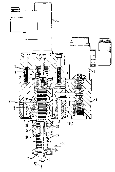
An embodiment of the invention is represented in Figure 1 and is described in
more detail
below.
Figure 1 shows a longitudinal section through the essential parts of the valve
2 according
to the invention. Its function-relevant components are a proportional magnet 4
for the actuation
of a proportional directional control valve 6 of the slide construction type,
a follow-up throttle
piston 8 for the control of the through-flow section 10 between a system input
side pl and a
system load-side p2, these sides also, as described in the cited document,
being interchangeable,
a differential guide piston or stepped piston 12, an inductive displacement
transducer 14 for this
guide piston 12, a pressure spring 16 within a sealed pressure-spring
compartment 18, which acts
upon the differential guide piston 12 in the direction of the follow-up
throttle piston 8, a pilot line
A between the proportional directional control valve 6 and the pressure-spring
compartment I 8,
through which line the oil pressure in the latter can be regulated, and an
edge control system of
seat construction type 20, here shown with conical bearing surfaces, between
the differential
guide piston 12 and the follow-up throttle piston 8.

CA 02054367 2001-03-14
-5-
The interaction of piston 8 and edge control system 20 is described in detail
in the above-
mentioned document, the back surface 22 of the follow-up throttle piston 8
being continually
pressurised, via a restrictor 24 and a longitudinal channel 26, at the input
pressure pl and being
connected, upon opening of the edge control system 20, via a central outlet
channel 28, to the
load side p2.
In contrast to the valve of the type mentioned in the preamble, i.e. that
described in the
cited document, the edge control system 20, in the case of the valve according
to the invention,
is not opened as a result of components corresponding to the differential
guide piston 12 being
raised by a pressure exerted by a proportional directional control valve 6
from the seat of the
edge control system 20, i.e. as a result of a control-side supplied pressure,
but instead by the
system pressure pl on a pressure shoulder 30 according to the invention acting
on the guide
piston 12. The opening of the edge control system 20 is now effected by the
spring compartment
18 being selectively depressurised via the work line A, and its closing, of
course, by the spring
compartment 18 being selectively pressurised through the connecting line A.
Very thorough studies and experiments have confirmed that, as a result of the
improvement according to the invention to the valve of the type mentioned in
the preamble, the
sought-after targets have been fully achieved, namely switching times which
are up to ten times
shorter and the repetitive accuracy possible as a result of the said closed-
loop control circuit. A
very desirable side-effect is obtained, namely that, as a result of the
pressure on the pressure
shoulder 30, the surface compression on the bearing surfaces of the edge
control system 20 is
decisively reduced, without however impairing the sealing function thereof.

Representative Drawing
A single figure which represents the drawing illustrating the invention.
Administrative Status

2024-08-01:As part of the Next Generation Patents (NGP) transition, the Canadian Patents Database (CPD) now contains a more detailed Event History, which replicates the Event Log of our new back-office solution.

Please note that "Inactive:" events refers to events no longer in use in our new back-office solution.

For a clearer understanding of the status of the application/patent presented on this page, the site Disclaimer , as well as the definitions for Patent , Event History , Maintenance Fee  and Payment History  should be consulted.

Event History

Description Date
Time Limit for Reversal Expired 2006-10-30
Inactive: IPC from MCD 2006-03-11
Letter Sent 2005-10-28
Inactive: Late MF processed 2002-10-31
Grant by Issuance 2001-12-25
Inactive: Cover page published 2001-12-24
Inactive: Final fee received 2001-09-25
Pre-grant 2001-09-25
Notice of Allowance is Issued 2001-06-26
Letter Sent 2001-06-26
Inactive: Approved for allowance (AFA) 2001-06-14
Amendment Received - Voluntary Amendment 2001-03-14
Inactive: S.30(2) Rules - Examiner requisition 2000-09-20
Inactive: Application prosecuted on TS as of Log entry date 1998-09-28
Letter Sent 1998-09-28
Inactive: Status info is complete as of Log entry date 1998-09-28
All Requirements for Examination Determined Compliant 1998-08-24
Request for Examination Requirements Determined Compliant 1998-08-24
Application Published (Open to Public Inspection) 1992-05-01

Abandonment History

There is no abandonment history.

Maintenance Fee

The last payment was received on 2001-10-03

Note : If the full payment has not been received on or before the date indicated, a further fee may be required which may be one of the following

  • the reinstatement fee;
  • the late payment fee; or
  • additional fee to reverse deemed expiry.

Patent fees are adjusted on the 1st of January every year. The amounts above are the current amounts if received by December 31 of the current year.
Please refer to the CIPO Patent Fees web page to see all current fee amounts.

Fee History

Fee Type Anniversary Year Due Date Paid Date
MF (application, 6th anniv.) - small 06 1997-10-28 1997-10-21
Request for examination - small 1998-08-24
MF (application, 7th anniv.) - small 07 1998-10-28 1998-09-30
MF (application, 8th anniv.) - small 08 1999-10-28 1999-10-27
MF (application, 9th anniv.) - small 09 2000-10-30 2000-08-21
Final fee - small 2001-09-25
MF (application, 10th anniv.) - small 10 2001-10-29 2001-10-03
Reversal of deemed expiry 2003-10-28 2002-10-31
MF (patent, 11th anniv.) - small 2002-10-28 2002-10-31
Reversal of deemed expiry 2003-10-28 2003-10-02
MF (patent, 12th anniv.) - small 2003-10-28 2003-10-02
2004-10-04
MF (patent, 13th anniv.) - small 2004-10-28 2004-10-04
Owners on Record

Note: Records showing the ownership history in alphabetical order.

Current Owners on Record
HYDROLUX S.A.R.L.
Past Owners on Record
HANS SCHWELM
Past Owners that do not appear in the "Owners on Record" listing will appear in other documentation within the application.
Documents

To view selected files, please enter reCAPTCHA code :


To view images, click a link in the Document Description column. To download the documents, select one or more checkboxes in the first column and then click the "Download Selected in PDF format (Zip Archive)" or the "Download Selected as Single PDF" button.

List of published and non-published patent-specific documents on the CPD .

If you have any difficulty accessing content, you can call the Client Service Centre at 1-866-997-1936 or send them an e-mail at CIPO Client Service Centre.


Document
Description 
Date
(yyyy-mm-dd) 
Number of pages   Size of Image (KB) 
Abstract 1993-11-26 1 16
Claims 1993-11-26 2 67
Description 1993-11-26 4 206
Drawings 1993-11-26 1 43
Abstract 2001-03-13 1 16
Description 2001-03-13 4 209
Claims 2001-03-13 2 64
Representative drawing 1999-06-27 1 44
Representative drawing 2001-11-25 1 23
Reminder - Request for Examination 1998-07-01 1 129
Acknowledgement of Request for Examination 1998-09-27 1 177
Commissioner's Notice - Application Found Allowable 2001-06-25 1 165
Late Payment Acknowledgement 2002-11-13 1 168
Maintenance Fee Notice 2005-12-27 1 172
Correspondence 2001-09-24 1 45
Fees 1994-12-15 1 18
Fees 1998-09-29 1 47
Fees 2001-10-02 1 33
Fees 1997-10-20 1 46
Fees 1999-10-26 1 43
Fees 2000-08-20 1 39
Fees 1996-09-25 1 46
Fees 1995-09-21 1 43
Fees 1994-11-10 1 43
Fees 1993-09-16 1 33
Fees 1994-12-22 1 38