Sélection de la langue

Search

Sommaire du brevet 2054367 

Énoncé de désistement de responsabilité concernant l'information provenant de tiers

Une partie des informations de ce site Web a été fournie par des sources externes. Le gouvernement du Canada n'assume aucune responsabilité concernant la précision, l'actualité ou la fiabilité des informations fournies par les sources externes. Les utilisateurs qui désirent employer cette information devraient consulter directement la source des informations. Le contenu fourni par les sources externes n'est pas assujetti aux exigences sur les langues officielles, la protection des renseignements personnels et l'accessibilité.

Disponibilité de l'Abrégé et des Revendications

L'apparition de différences dans le texte et l'image des Revendications et de l'Abrégé dépend du moment auquel le document est publié. Les textes des Revendications et de l'Abrégé sont affichés :

  • lorsque la demande peut être examinée par le public;
  • lorsque le brevet est émis (délivrance).
(12) Brevet: (11) CA 2054367
(54) Titre français: SOUPAPE D'ETRANGLEMENT REGLABLE A DEPLACEMENT PROPORTIONNEL AVEC RETROACTION
(54) Titre anglais: ADJUSTABLE PROPORTIONAL THROTTLE-VALVE WITH FEEDBACK
Statut: Périmé et au-delà du délai pour l’annulation
Données bibliographiques
(51) Classification internationale des brevets (CIB):
  • F16K 11/07 (2006.01)
  • F15B 13/043 (2006.01)
  • F16K 31/40 (2006.01)
(72) Inventeurs :
  • SCHWELM, HANS (Luxembourg)
(73) Titulaires :
  • HYDROLUX S.A.R.L.
(71) Demandeurs :
  • HYDROLUX S.A.R.L. (Luxembourg)
(74) Agent: GOWLING WLG (CANADA) LLP
(74) Co-agent:
(45) Délivré: 2001-12-25
(22) Date de dépôt: 1991-10-28
(41) Mise à la disponibilité du public: 1992-05-01
Requête d'examen: 1998-08-24
Licence disponible: S.O.
Cédé au domaine public: S.O.
(25) Langue des documents déposés: Anglais

Traité de coopération en matière de brevets (PCT): Non

(30) Données de priorité de la demande:
Numéro de la demande Pays / territoire Date
87 831 (Luxembourg) 1990-10-31

Abrégés

Abrégé anglais


The throttle-part of the valve comprises a two-way seat valve with a follow-up
throttle
piston. A differential guide piston allows to position the follow-up throttle
piston via an edge
control system. The differential guide piston is biased via a spring in a
pressure-spring
compartment in the direction of the closed position of the edge control
system. A proportional
directional control valve, which is actuated by a magnet, allows to pressurise
or depressurise the
pressure-spring compartment via a pilot line A, whilst the position of the
guide piston is
determined by an inductive displacement transducer.

Revendications

Note : Les revendications sont présentées dans la langue officielle dans laquelle elles ont été soumises.


-6-
CLAIM
1. An adjustable proportional throttle valve comprising:
a housing with a fluid inlet port and a fluid outlet port;
a throttle piston axially movable in said housing, said throttle piston having
a throttling
end and an opposite piston end, said throttling end co-operating with a valve
seat in said housing
to form a two-way throttling valve between said fluid inlet port and said
fluid outlet port;
a control chamber in said housing, said piston end of said throttle piston
defining in said
control chamber a pressure shoulder;
an inlet channel extending through said throttle piston to bring said control
chamber in
fluid communication with said fluid inlet port, said inlet channel including a
flow re strictor;
an outlet channel extending through said throttle piston to bring said control
chamber in
fluid communication with said fluid outlet port, said outlet channel having an
axial opening in
said control chamber;
a pressure-spring chamber axially spaced in said housing from said control
chamber;
a differential guide piston axially movable in said housing in alignment with
said throttle
piston, said differential guide piston having a stepped design with a first
end exposed to fluid
pressure in said control chamber and a second end exposed to fluid pressure in
said pressure-
spring chamber;
a follow-up piston axially extending from said first end of said differential
guide piston,
said follow-up piston having a smaller diameter than said first end of said
stepped guide piston
so that a pressure shoulder surrounds said follow-up piston on said first end
of said differential
guide piston, said follow-up piston co-operating with said axial opening of
said outlet channel
to form an edge control system of seat-type construction;
a spring engaging said differential guide piston in said pressure-spring
chamber so as to
bias it towards said throttle piston;

-7-
a proportional directional control valve having an inlet for connection to a
source of
pressure fluid, an outlet in fluid communication with said pressure-spring
chamber and control
means for controlling the flow of pressure fluid through said outlet, so as to
be able to pressurise
or depressurise said pressure-spring chamber;
a proportional magnet associated with said proportional directional control
valve for
actuation of said control means; and
an inductive displacement transducer associated with said guide piston;
wherein said proportional magnet and said inductive displacement transducer co-
operate
in a closed loop control system to determine the position of said throttle
piston as a function of
said input signal of said proportional magnet.

Description

Note : Les descriptions sont présentées dans la langue officielle dans laquelle elles ont été soumises.

CA 02054367 2001-03-14
-2-
ADJUSTABLE PROPORTIONAL THROTTLE-VALVE WITH FEEDBACK
The invention relates to an adjustable proportional throttle valve.
Adjustable proportional throttle valves with feedback are commonly known and
find
application in all hydraulic assemblies. Amongst the many applications, there
are various, e.g.
hydraulic presses and goliath cranes, with which, despite the size of the
equipment and the
magnitude of the hydraulic operating pressure, very precise movements have to
be carried out
and accordingly high demands are placed upon the precision and accuracy of the
mode of
operation of the throttle valves.
Known prior art throttle valves however only fulfilled the defined
requirements partially
or inadequately. Firstly, these throttle valves required excessive regulating
forces in the control
part, which is disadvantageous from the economic viewpoint. Secondly, the
known throttle
valves possessed over-long switching times for the various applications, which
put their use into
question. Moreover, these known throttle valves were subjected to high wear
and tear, so that
their working life was insufficient.
U.S. Patent No. 4,662,600 provides a description of an adjustable proportional
throttle
valve, with which the costly pilot control system with power feedback is
eliminated and the
structural size can be reduced, whilst still maintaining the basic advantages
offered by these
valves.
The principal concept of the invention described in U.S. Patent No. 4,662,600
consists
in making use of the oil pressure of the actual work system as a servo-energy
supplier for the
actuation of those valve components that determine the volume flow, thereby,
in addition to other
benefits, substantially relieving the control part. This object has been
achieved by means of a
follow-up throttle piston arrangement.
For the characteristics of the mode of operation of the valve presented in U.
S. Patent No.
4,662,600, reference should be made to this document.

CA 02054367 2001-03-14
-3-
The object of the present invention is to perfect valves of the type disclosed
in U. S. Patent
No. 4,662,600 still further, by quite substantially reducing the valve-
switching times and
decisively improving the repetitive accuracy.
This object is achieved, by an adjustable proportional throttle valve
comprising: a housing
with an fluid inlet port and a fluid outlet port; a throttle piston axially
movable in said housing,
said throttle piston having a throttling end and an opposite piston end, said
throttling end co-
operating with a valve seat in said housing to form a two-way throttling valve
between said fluid
inlet port and said fluid outlet port; a control chamber in said housing, said
piston end of said
throttle piston defining in said control chamber a pressure shoulder; an inlet
channel extending
through said throttle piston to bring said control chamber in fluid
communication with said fluid
inlet port, said inlet channel including a flow restrictor; an outlet channel
extending through said
throttle piston to bring said control chamber in fluid communication with said
fluid outlet port,
said outlet channel having an axial opening in said control chamber; a
pressure-spring chamber
axially spaced in said housing from said control chamber; a differential guide
piston axially
movable in said housing in alignment with said throttle piston, said
differential guide piston
having a stepped design with a first end exposed to fluid pressure in said
control chamber and
a second end exposed to fluid pressure in said pressure-spring chamber; a
follow-up piston
axially extending from said first end of said differential guide piston, said
follow-up piston
having a smaller diameter than said first end of said stepped guide piston so
that a pressure
shoulder surrounds said follow-up piston on said first end of said
differential guide piston, said
follow-up piston co-operating with said axial opening of said outlet channel
to form an edge
control system of seat-type construction; a spring engaging said differential
guide piston in said
pressure-spring chamber so as to bias it towards said throttle piston; a
proportional directional
control valve having an inlet for connection to a source of pressure fluid, an
outlet in fluid
communication with said pressure-spring chamber and control means for
controlling the flow
of pressure fluid through said outlet, so as to be able to pressurise or
depressurise said pressure-
spring chamber; a proportional magnet associated with said proportional
directional control valve
for actuation of said control means; and an inductive displacement transducer
associated with
said guide piston; wherein said proportional magnet and said inductive
displacement transducer

CA 02054367 2001-03-14
-4-
co-operate in a closed loop control system to determine the position of said
throttle piston as a
function of said input signal of said proportional magnet.
In other words, the proportional magnet controlled directional control valve
positions the
differential guide-piston, through pressurisation or depressurisation of the
pressure-spring
chamber, against the force of an input pressure acting in the control chamber
on the pressure
shoulder of the differential guide piston. Hence, it also positions, through
the effect of an input-
side or load-side oil pressure of the work system, the follow-up throttle
piston. It follows that the
throttle-flow section at the valve seat is determined independently of the
input pressure and load
pressure, purely as a function of the input signal to the proportional magnet.
As a result of a special stepped design of the differential guide piston, the
surface
compression in the area of the bearing surface is greatly reduced without,
however, impairing the
sealing function. The valve is particularly characterised by high speeds, i.e.
short switching
times, associated with low control-oil volumes and low control pressure.
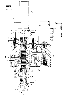
An embodiment of the invention is represented in Figure 1 and is described in
more detail
below.
Figure 1 shows a longitudinal section through the essential parts of the valve
2 according
to the invention. Its function-relevant components are a proportional magnet 4
for the actuation
of a proportional directional control valve 6 of the slide construction type,
a follow-up throttle
piston 8 for the control of the through-flow section 10 between a system input
side pl and a
system load-side p2, these sides also, as described in the cited document,
being interchangeable,
a differential guide piston or stepped piston 12, an inductive displacement
transducer 14 for this
guide piston 12, a pressure spring 16 within a sealed pressure-spring
compartment 18, which acts
upon the differential guide piston 12 in the direction of the follow-up
throttle piston 8, a pilot line
A between the proportional directional control valve 6 and the pressure-spring
compartment I 8,
through which line the oil pressure in the latter can be regulated, and an
edge control system of
seat construction type 20, here shown with conical bearing surfaces, between
the differential
guide piston 12 and the follow-up throttle piston 8.

CA 02054367 2001-03-14
-5-
The interaction of piston 8 and edge control system 20 is described in detail
in the above-
mentioned document, the back surface 22 of the follow-up throttle piston 8
being continually
pressurised, via a restrictor 24 and a longitudinal channel 26, at the input
pressure pl and being
connected, upon opening of the edge control system 20, via a central outlet
channel 28, to the
load side p2.
In contrast to the valve of the type mentioned in the preamble, i.e. that
described in the
cited document, the edge control system 20, in the case of the valve according
to the invention,
is not opened as a result of components corresponding to the differential
guide piston 12 being
raised by a pressure exerted by a proportional directional control valve 6
from the seat of the
edge control system 20, i.e. as a result of a control-side supplied pressure,
but instead by the
system pressure pl on a pressure shoulder 30 according to the invention acting
on the guide
piston 12. The opening of the edge control system 20 is now effected by the
spring compartment
18 being selectively depressurised via the work line A, and its closing, of
course, by the spring
compartment 18 being selectively pressurised through the connecting line A.
Very thorough studies and experiments have confirmed that, as a result of the
improvement according to the invention to the valve of the type mentioned in
the preamble, the
sought-after targets have been fully achieved, namely switching times which
are up to ten times
shorter and the repetitive accuracy possible as a result of the said closed-
loop control circuit. A
very desirable side-effect is obtained, namely that, as a result of the
pressure on the pressure
shoulder 30, the surface compression on the bearing surfaces of the edge
control system 20 is
decisively reduced, without however impairing the sealing function thereof.

Dessin représentatif
Une figure unique qui représente un dessin illustrant l'invention.
États administratifs

2024-08-01 : Dans le cadre de la transition vers les Brevets de nouvelle génération (BNG), la base de données sur les brevets canadiens (BDBC) contient désormais un Historique d'événement plus détaillé, qui reproduit le Journal des événements de notre nouvelle solution interne.

Veuillez noter que les événements débutant par « Inactive : » se réfèrent à des événements qui ne sont plus utilisés dans notre nouvelle solution interne.

Pour une meilleure compréhension de l'état de la demande ou brevet qui figure sur cette page, la rubrique Mise en garde , et les descriptions de Brevet , Historique d'événement , Taxes périodiques et Historique des paiements devraient être consultées.

Historique d'événement

Description Date
Le délai pour l'annulation est expiré 2006-10-30
Inactive : CIB de MCD 2006-03-11
Lettre envoyée 2005-10-28
Inactive : TME en retard traitée 2002-10-31
Accordé par délivrance 2001-12-25
Inactive : Page couverture publiée 2001-12-24
Inactive : Taxe finale reçue 2001-09-25
Préoctroi 2001-09-25
Un avis d'acceptation est envoyé 2001-06-26
Lettre envoyée 2001-06-26
Inactive : Approuvée aux fins d'acceptation (AFA) 2001-06-14
Modification reçue - modification volontaire 2001-03-14
Inactive : Dem. de l'examinateur par.30(2) Règles 2000-09-20
Inactive : Dem. traitée sur TS dès date d'ent. journal 1998-09-28
Lettre envoyée 1998-09-28
Inactive : Renseign. sur l'état - Complets dès date d'ent. journ. 1998-09-28
Toutes les exigences pour l'examen - jugée conforme 1998-08-24
Exigences pour une requête d'examen - jugée conforme 1998-08-24
Demande publiée (accessible au public) 1992-05-01

Historique d'abandonnement

Il n'y a pas d'historique d'abandonnement

Taxes périodiques

Le dernier paiement a été reçu le 2001-10-03

Avis : Si le paiement en totalité n'a pas été reçu au plus tard à la date indiquée, une taxe supplémentaire peut être imposée, soit une des taxes suivantes :

  • taxe de rétablissement ;
  • taxe pour paiement en souffrance ; ou
  • taxe additionnelle pour le renversement d'une péremption réputée.

Veuillez vous référer à la page web des taxes sur les brevets de l'OPIC pour voir tous les montants actuels des taxes.

Historique des taxes

Type de taxes Anniversaire Échéance Date payée
TM (demande, 6e anniv.) - petite 06 1997-10-28 1997-10-21
Requête d'examen - petite 1998-08-24
TM (demande, 7e anniv.) - petite 07 1998-10-28 1998-09-30
TM (demande, 8e anniv.) - petite 08 1999-10-28 1999-10-27
TM (demande, 9e anniv.) - petite 09 2000-10-30 2000-08-21
Taxe finale - petite 2001-09-25
TM (demande, 10e anniv.) - petite 10 2001-10-29 2001-10-03
Annulation de la péremption réputée 2003-10-28 2002-10-31
TM (brevet, 11e anniv.) - petite 2002-10-28 2002-10-31
Annulation de la péremption réputée 2003-10-28 2003-10-02
TM (brevet, 12e anniv.) - petite 2003-10-28 2003-10-02
2004-10-04
TM (brevet, 13e anniv.) - petite 2004-10-28 2004-10-04
Titulaires au dossier

Les titulaires actuels et antérieures au dossier sont affichés en ordre alphabétique.

Titulaires actuels au dossier
HYDROLUX S.A.R.L.
Titulaires antérieures au dossier
HANS SCHWELM
Les propriétaires antérieurs qui ne figurent pas dans la liste des « Propriétaires au dossier » apparaîtront dans d'autres documents au dossier.
Documents

Pour visionner les fichiers sélectionnés, entrer le code reCAPTCHA :


Pour visualiser une image, cliquer sur un lien dans la colonne description du document. Pour télécharger l'image (les images), cliquer l'une ou plusieurs cases à cocher dans la première colonne et ensuite cliquer sur le bouton "Télécharger sélection en format PDF (archive Zip)" ou le bouton "Télécharger sélection (en un fichier PDF fusionné)".

Liste des documents de brevet publiés et non publiés sur la BDBC .

Si vous avez des difficultés à accéder au contenu, veuillez communiquer avec le Centre de services à la clientèle au 1-866-997-1936, ou envoyer un courriel au Centre de service à la clientèle de l'OPIC.


Description du
Document 
Date
(aaaa-mm-jj) 
Nombre de pages   Taille de l'image (Ko) 
Page couverture 1993-11-27 1 13
Abrégé 1993-11-27 1 16
Revendications 1993-11-27 2 67
Description 1993-11-27 4 206
Dessins 1993-11-27 1 43
Page couverture 2001-11-26 1 50
Abrégé 2001-03-14 1 16
Description 2001-03-14 4 209
Revendications 2001-03-14 2 64
Dessin représentatif 1999-06-28 1 44
Dessin représentatif 2001-11-26 1 23
Rappel - requête d'examen 1998-07-02 1 129
Accusé de réception de la requête d'examen 1998-09-28 1 177
Avis du commissaire - Demande jugée acceptable 2001-06-26 1 165
Quittance d'un paiement en retard 2002-11-14 1 168
Avis concernant la taxe de maintien 2005-12-28 1 172
Correspondance 2001-09-25 1 45
Taxes 1994-12-16 1 18
Taxes 1998-09-30 1 47
Taxes 2001-10-03 1 33
Taxes 1997-10-21 1 46
Taxes 1999-10-27 1 43
Taxes 2000-08-21 1 39
Taxes 1996-09-26 1 46
Taxes 1995-09-22 1 43
Taxes 1994-11-11 1 43
Taxes 1993-09-17 1 33
Taxes 1994-12-23 1 38