Note: Descriptions are shown in the official language in which they were submitted.
- 1- 2~38~
A tolerance rivet for highly stressed riveted joints
The invention relates to a tolerance rivet for
highly stressed riveted joints possessing a shank whose
length is harmonized with the two components to be
joined, followed by a retaining piece interacting with
a retaining collar and provided with grooves on its
circumference, whereby an enveloping jacket that links
the root diameters of the grooves widenes conicallY
from the head of the tolerance rivet toward its
opposite free end, and the grooves on the retaining
piece possess decreasing groove width and increasing
asymmetry of the groove profile in the same direction.
A tolerance rivet of this type is known from DE-PS
32 15 228. Immediately after the retaining piece with
the grooves, the tolerance rivet possesses a tear-off
groove forming a single predetermined breaking point
and a subsequent tear-off piece. The grooves on the
circumference of the retaining piece have V-shaped
sections in the direction from the tolerance rivet head
toward its opposite free end with groove angles
decreasing in the same direction, thus leading to a
stepwise decreasing groove width in this direction, if
the projecting parts between the grooves end on a
cylindrical enveloping jacket. In connection with an
enveloping jacket connecting the root diameters of the
grooves and widening conically from the tolerance rivet
head toward its opposite free end, the groove depth
decreases in this direction. Besides, in this direction
the V-shaped sections of the various grooves are
arranged with different inclinations thus leading to an
increasing asymmetry of the groove profile in the
direction toward the free end of the retaining piece.
In the case of special applications, i.e. if the
components to be braced are subject to a gaping motion,
that is a swivel motion of the components against one
another across an axis situated in its tangent plane,
there may be premature damage done to the tolerance
~ - 2 205438~
rivet in the area of the retaining piece, thus
impairing service life. Such stresses may occur for
example in the case of structures in airplanes. In the
case of excessive stress, there is danger of breakage
at such tolerance rivets.
From US-PS 3 915 053 another tolerance rivet is
known in the case of which there is also one single
tear-off groove serving as predetermined breaking point
so that the length of the tolerance rivet shank is
harmonized with the thickness of the components to be
joined. Hence, tolerance rivets with shanks of various
lengths are required for different component
thicknesses. In order to distribute the stress at the
retaining piece and at the retaining collar as equally
as possible onto the axial extension of the grooves of
the retaining piece, the groove section-from the shank
toward the tear-off groove is increased and/or also the
depth of the grooves - if seen radially - is enhanced
in this direction. This creates an enclosing jacket
connecting the root diameters of the grooves, which
widens conically from the free end of the tolerance
rivet toward the head or shank. Therefore, the
enclosing jacket is arranged in an inversely conical
way when compared to the tolerance rivet of the kind
mentioned at the outset. However, in the direction from
the head to the tear-off groove, groove width is
increased also in this case. Such a design facilitates
the putting-on of the retaining collar to be formed and
of the clamping tool. Nonetheless, the flowage of the
material of the retaining collar into the grooves is
not satisfactory because the grooves located next to
the head have a smaller section, while the material of
the retaining collar next to the tear-off groove is
subject to the greatest deformation, i.e. it flows best
in this place.
It is the object of this invention to the increase
the dynamic carrying capacity of a tolerance rivet
having the characteristics described at the outset, in
_ 3 _ 20~38~
order to improve in this way also the service life of
the joint between the tolerance rivet and the
components, even in the case of adverse gaping
stresses.
This is achieved, according to the invention, in
that the first groove, arranged at the retaining piece
of the tolerance rivet immediately after the shank in
the direction toward its free end, possesses a rounded
shaping whose area is strain-hardened. The rounded
shaping may consist of one or several radii, whereby
none of the radii should be smaller than x mm. However,
the strain-hardening of the first groove is of
particular importance in connection with the rounded
shaping, at least in the area of the root diameter or
of the rounded shaping. By means of this strain-
hardening process two effects are achieved. On the one
hand, the dynamic carrying capacity of the tolerance
rivet is increased where the tolerance rivet has its
smallest diameter and where, on the other hand, it is
subject to the greatest stress. A stress concentration
which may possibly occur in the state of the art when
arranging V-shaped grooves that even in their root
diameter have more or less sharp edges is eliminated
through the rounded shaping in connection with the
strain-hardening, or its adverse effects are at least
attenuated. At the same time, the strain-hardening
leads to a smoothing and evening-out of the surface in
this place so that here the material of the retaining
collar encounters less friction and may therefore flow
with greater ease. The larger the strain-hardened area,
the greater are the consequences of this second effect.
It is therefore not quite favorable to strain-harden
only a small part of the surface of the first groove in
the area of the root diameter; the strain-hardening may
in fact also include the adjacent areas which do not
belong to the rounded shaping of the groove root.
In this way, it is possible that the transition
area of the shank coming after the root diameter of the
20~389
,....
-- 4 --
first groove in the direction toward the head is also
strain-hardened. Strain-hardening may be provided
continuously from the root diameter of the first groove
down to a certain depth of the shank length, that is in
an area where the cylindric part of the shank has
already been reached.
The transition area between the first groove and
the shank following immediately after in the direction
toward the head of the tolerance rivet may possess a
shaping composed of several radii. Hence, also in this
case a rounded shaping e.g. in the form of a three-
center curve may be provided. The shaping may be the
result of machining or a non-cutting shaping process,
the strain-hardening being accomplished simultaneously
with the non-cutting shaping. By means of this design,
not only the hitherto described advantages are
achieved. There exists the further advantage that the
pressing-in process of the tolerance rivet shank into
the bore hole of the components to be joined is
facilitated. By means of the strain hardening the
surface becomes smoother and the friction during the
pressing-in process into the bore hole of the
components is reduced. At the same time, it is avoided
that damage is done to the bore hole during the
pressing-in process. Such damage by striation is known
in the state of the art. It is another advantage that
by means of strain-hardening, shape and surface faults
in the transition area of the shank toward the first
groove are in general eliminated, also in the area of
tolerances, and thus the dynamic carrying capacity in
this area of the texture is increased.
The strain-hardened area(s) may be rolled. Such a
rolling process represents a particularly simple and
effective processing step, in order to accomplish the
strain-hardening.
The surface of all or some of the grooves
following the first groove may be shaped prior to or
after a heat treatment by means of a non-cutting
205~38~
process. By this, the flow conditions of the material
of the retaining collar are improved in this area of
the retaining piece. Yet it is also possible that the
surface in the area of the first groove possesses
smooth texture and in the area of the subsequent
grooves coarse texture. The smooth and the coarse
texture may be accomplished by rolling. The smooth
texture favors a better moulding of the material of the
retaining collar into the grooves of the retaining
piece. The coarse texture serves the purpose of
increasing the transmissibility of the retention forces
in the area of the grooves following the first groove.
On the other hand, it is also possible that the surface
in the area of the first groove is of a smooth texture
and that in the area of the subsequent grooves it is of
an even smoother texture. Both textures may be
accomplished by rolling and strain-hardening, and they
favor the flowage of the material of the retaining
collar also in the area of the subsequent grooves.
Apart from rolling, there are other possibilities
for accomplishing strain-hardening. Hence, the strain-
hardened area(s) can also be accomplished by shot
peening. When using spherical shot-peening material the
surface is smoothened and strain-hardened. When using
sharp-edged, splintery material the surface is made
coarse.
The invention is explained and described in
further detail by means of different embodiments. The
drawings represent as follows:
Figure 1 is a schematic diagram with several steps
according to the setting process of a tolerance rivet;
Figure 2 is a sectional view demonstrating the
change in shape of the retaining collar before and
after the setting process;
Figure 3 is a detail drawing of the tolerance
rivet as tear-off type, and
Figure 4 is a detail drawing of the tolerance
rivet as press-in type.
20~3~
-- 6 --
The tolerance rivet is inserted into a prepared
bore hole in the components 1 and 2 to be joined. It
possesses a smooth, mostly cylindrical shank 3 which
has a head 4 on one end. At the other end of the shank
3 the material of the tolerance rivet ends into a
retaining piece 5 equipped with grooves 9. The
retaining piece 5 interacts with a retaining collar 6
made of a highly deformable, flowing material, for
example of aluminum, and which flows into the grooves 9
of the retaining piece S when the retaining collar 6 is
deformed during the setting process of the tolerance
rivet. By way of a tear-off groove, a tear-off piece 8
forming a predetermined breaking point is connected to
the retaining piece 5. The tear-off piece 8 is equipped
with threads or turned grooves serving the purpose of
receiving a clamping tool.
The process of the setting of the tolerance rivet
is made clear by the sequence of figures la through ld.
According to figure la the tolerance rivet with its
shank 3 is inserted into the bore hole of the
components 1, 2 until its head 4 makes contact with the
component 2. Then, the retaining collar 6 is slid on.
It possesses a bore hole that permits its being slid
onto the tolerance rivet. According to figure lb, a
clamping tool with its clamping jaws 10 is brought into
action. In the course of this process a clamping bush
11 embraces the tear-off piece 8. By means of the
clamping tool a high tensile stress acts upon the
tolerance rivet, while at the same time the retaining
collar 6 is deformed in a way that its material flows
and is pressed into the grooves 9 of the retaining
piece 5. This can be seen in figure lc. As soon as the
tensile stress that is required for setting the
tolerance rivet is exceeded, the deformation of the
retaining collar 6 ends and the tear-off piece 8 breaks
in the area of the tear-off groove 7 as is illustrated
in figure ld.
~ - 7 - 2~38~
Figure 2 shows a blown-up view of details of the
design and the interaction of the tolerance rivet in
the area of the retaining piece 5 and the retaining
collar 6. The left half of the drawing shows the
retaining collar prior to its deformation and the right
half represents the retaining collar after its
deformation. The retaining collar 6 is deformed from an
approximately cylindrincal shape into conical shape,
while in the area of a bearing surface its material
will flow outwards in a bead-like way. During the
setting process the retaining collar 6 is subject to
omnilateral compressive strains until its total
deformation. The very moment the tear-off piece 8 is
torn off and the fastening device i5 pulled back, the
stresses on acting the retaining collar 6 are relieved
toward all sides. In this way there is also a relief
between the tolerance rivet in the fastening area, and
the invested prestress is decreasing somewhat. With the
expected setting of the entire joint the retaining
collar 6 is further relieved, which causes it to expand
by elasticity and the derormation angle rho to
decrease.
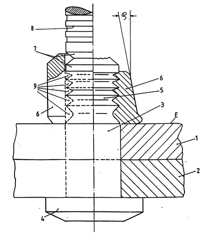
Figures 3 and 4 show further essential details of
the tolerance rivet; figure 3 shows two semisections of
tolerance rivets of different lengths according to the
tear-off type, and figure 4 is a view of a press-in
tolerance rivet. In the area of the retaining piece 5
the grooves 9, starting from a first groove coming
right after the shank 3 down to a last groove 9 which
is followed by the tear-off groove 7, are designed in a
way that the root diameters dl, d2, etc. of the
subsequent grooves increase gradually from the head 4
or shank 3 toward the free end of the tolerance rivet.
The groove profile angle y diminishes in the direction
of yl, y2, etc. toward the tear-off piece 8 or toward
the free end. ~ence, also the groove width a diminishes
in the direction al, a2, etc. The first groove 9
following the shank 3 possesses a mostly symmetrical
2~ ~389
shape with an approximately V-shaped cross-section,
this section being located approximately symmetrical to
a diametral plane according to dl. While the other
grooves 9 also have V-shaped sections in the direction
S toward the free end of the tolerance rivet, its
position and arrangement, however, shifts in terms of
an increasing asymmetry, i.e~ in such a way that the
areas of support 19 are arranged with increasing
steepness in comparison to the first groove 9. There
can be a steady transition in this groove design from
the first to the last groove 9. The service life of the
tolerance rivet is favored by the comparatively great
groove width al of the f irst groove 9. In the area of
its root diameter dl this first groove 9 possesses a
rounded shaping according to the radius r3 (figure 3)
or to several subsequent radii r3 and r4 (figure 4). By
means of this rounded shaping a stress concentration in
the groove root is avoided. Of importance in connection
with the rounded shaping is a strain-hardened area 13
represented by crosses and having approximately an
axial length 14. This rounded shaping in connection
with the strain-hardened area 13 brings about an
increase in the dynamic carrying capacity and thus in
the service life of the tolerance rivet.
It constitutes an advantage if the transition area
15 toward the shank 3 following the area 13, which in
this place is represented by dashed lines and may have
an axial length 16, is also strain-hardened. One
recognizes that the transition area 15 reaches about as
far into the shank 3 that it will end in the
cylindrical area of the shank 3. The shaping in this
transition area 15 may also be rounded off, and several
radii rl and r2 may follow one another, in order to
achieve a shaping similar to a three-center curve.
These designs are valid for embodiment examples of both
figures 3 and 4,
Furthermore, figure 4 shows that a strain-
hardening, starting from the area 13, may be provided
-` 9 2~5~3~9
in the root diameter dl of the first groove 9 and also
down into the area of the other ensuing groove 9. Here,
a first area 17 is represented by dashed lines which
borders on to the area 13 of the first groove 9 and
reaches up to approximately the third groove 9. Like
the areas 13 and 15, this area 17 possesses a smooth
surface so that in this case the flowage of the
material of the retaining collar 6 into the groove 9 is
favored. A smooth design is particularly favorable in
the transition area 15, because the bearing surface e
of the component 1 hampers the flowage.
It is possible, in particular in the area of the
grooves 9 facing the free end of the tolerance rivet,
that is in the area of the last grooves 9, to provide
another strain-hardened area 18, illustrated by dots.
Here, it is recommendable to accomplish the strain-
hardening which may for example be achieved by means of
a rolling process or by blasting with shot-peening
material, not with a smooth surface but with a coarse
texture. In the area of these last grooves 9 there is
no flow impedance of the material of the retaining
collar 6 which is why in this place the material is
flowing well anyway. Due to the coarse surface in the
area 18, especially in the areas of support, the
transmissible prestress is increased. It is evident
that in the embodiment example of figure 4 the clamping
tool acts upon the area of a bore hole 20.
- lo- 2~389
List of reference signs:
1 = component
2 = component
3 = shank
4 = head
5 = retaining piece
6 = retaining collar
7 = tear-off groove
8 - tear-off piece
9 = grooves
10 = clamping jaw
11 = clamping bush
12 = enveloping jacket
13 = strain-hardened area
14 = axial length
15 = transition area
16 = axial length
17 = area
18 = area
19 = areas of support
20 = bore hole