Note: Descriptions are shown in the official language in which they were submitted.
2054445
BACRGRO~ND OF TH~ 1N ~N~ION
This invention relates generally to wire or
cable severing, as well as stripping sheathing from
severed wire sections and more particularly, it
s concerns unusual advantages, method and apparatus to
effect severing of a wire or cable into two sections,
and strlpping of sheathing off end of both sections,
with minimal motions of severing and ~tripping elements
and in minimum time
There is continual need for equipment capable
of severing wire or cable into sections, and also
capable of rapidly and efficiently stripping ~heathing
off ends of those sections. It i8 desirable that these
functions be carried out a8 a wire or cabl~ travels
along generally the same axis, i.e., progresses
forwardly, and that multiple wire and cable sections of
selected length be produced, each having its opposite
ends stripped of sheathing, to expose bare metal core
wire at each end. Further, lt i8 desirable that
simple, radial and axial stripping ad~ustments be
achieved upon multiple wire sections.
S~MMARY OF T~B lN~hl~ON
It 1~ a ma~or ob~ect of the invention to
provide apparatus and method meeting th~ above need.
The word "wire" will be used to lnclude cable within
its ~cope, and vice vQrsa.
Basically, the method involves proces~ing the
- 2 -
20544~
wire into sections as byw displacing the wire endwise
along an axis to a first positions severlng the wire
thereby to form wire forward and rearward sections, the
forward section having a rearward end portion, and the
rearward section having a forward end portion; and
stripping sheathing from the forward section rearward
portion and from the rearward section forward portion
thereby to expose wire cores at tho6e end portions.
In this regard, the cutter means typically
may include three blade pairs, each pair including two
blades located at opposlte sides of the axis, both
blades of one palr being displaced toward the wlre to
sever the wire, and both blades of the remaining two
pairs being displaced toward the wlre sectlons to strip
sheathlng from the rearward and forward portlons durlng
controlled endwise displacement of the sections. Both
blades of one pair are typically displaced into
overlapping relation to sever the wlre, and both blades
of each of the remaining two pairs are displaced to cut
only into opposite sldes of the sheathing and to strip
sheathing from the end portions of the sections as the
sections are displaced endwise simultaneously.
Another ob~ect is to displace the two
sections endwise, thereby to displace wire
incorporating one of the sections to the first
position. The method further includes the step of
separating the sectlons axlally relatively endwise
after the step of severlng of the wlre and prlor to the
step of stripping of sheathlng fro~ the sectlon end
portlons. In addltlon, the method may include the step
2054445
of further separating the sections axially relatively
endwise after the blades of the rer~n~ng two pairs
have been displaced toward the wire sections to cut
into the sheathing, thereby to pull sheathing slugs off
the wire end portions to expose the wire end cores.
Yet another ob~ect is to guide displacement
of the wire endwise along the axis, at locations
between blade pairs: and in this regard, both of the
forward and rearward 6ections may be so guided.
A further ob~ect is to carry out separation
of the forward and rearward wire sections by advancing
one section and retracting the other section, relative
to the one blade pair: and the method typically
involves carrying out further separation of the
sections by further advancing the one section and
further retracting the other section, relative to each
one blade pair.
Apparatus for processing wire into sections,
as referred to, and to strip sheathing from the
sections to expose wire core ends, basically includes:
a) conveyor means for displacing the wire,
including the sections, axially endwise,
b) first cutter means including multiple
blades located for movement toward the axis, and a
first drive means for controllably displacing the
multiple cutter blade~ toward the axi~ to sever the
wire,
c) second and third cutter means each
including multiple blades located for movement toward
the axis, and additional drive mean~ for controllably
205~ 5
displacing the multiple blades of the second and thlrd
cutter means toward the axis to cut into the sheathing,
the second and third cutter means respectlvely located
at axially opposite sides of the flrst cutter means and
s axially spaced therefrom,
d) and drive means to controllably drive
the conveyor means to
i) position the wire to be severed by
the first cutter means, thereby to
produce forward and rearward wire
sections,
ii) relatively displace the sections
axially, into positions to enable
penetration of thQ second and third
cutter means blades into the
sheathing, for 6ubseguent stripping
of sheathing from a rearward
portion of the forward sectlon and
from a forward portion of the
rearward section, as during
controlled endwise displacement of
the sections by the conveyor means.
Forward and rearward pairs of endles~
conveyors are typically employed, each palr of
conveyors defining a wire gripping zone, such zones
maintaln-ed in alignment with the wire sQction~ during
separation of the lattQr. Mean~ i~ further provided to
maintain one conveyor of each pair laterally displaced
relatively toward the othQr conveyor of the pair to
clamp the wire sections bQtween the convQyors of the
- 5 -
20544~5
pairs durlng thQ further separation of the wire
sections, and operating the conveyor pairs in endle6s
relation to effect the relative separation in a
longltudinal direction.
As will also be seen, the blades of the first
cutter means typically have positions of relative
overlap to sever the wire, in response to operation of
the first drive means: and the blades of the second and
third cutter means typlcally have positions of
penetration only into the ~heathing of the section end
portions and to such depths as to enable stripping of
the sheathing end portions in response to the
controllable driving of the conveyor means.
In addltion. ~ovel and unu~ually effective
apparatus is provided to advance the three sets of
blades simultaneously toward the wire to first sever,
and subsequently strip wire sheathing, at multiple
axial locatlons, wire sections being axlally displaced
while severing blades are closed, and prior to closure
of sheath stripping blades toward the sections.
~hese and other ob~ects and advantages of the
invention, as well as the details of an illustrativQ
embodiment, will be more fully understood from the
following specification and drawinqs, in which:
DRAWING DFSCRIPTION
Figs. la--lf are dlagrammatic views showing
step~ in the method of wirQ or cable processings
Fig. 2 iB a sidQ view elevation showing wire
- 6 -
205444..5
displacing and processing apparatus:
Flg. 3 i8 a top plan view 6howing the
apparatus of Fig. 2;
Flg. 4 is an end view, taken in elevation,
showing wire belt displacing drive apparatus~
Fig. 5 i8 an elevation showing spring urging
of wire drive belts;
Fig. 6 is an enlarged cross-section taken in
elevation to show sheathing stripping actuator
structure;
Fig. 7 is a view like Fig. 6 but showing the
blades in advanced positions:
Fig. 8 is a plan view of the Fig. 6 and Fig.
7 mechanism;
Fig. 9 is an end view showing wire severing
blades in wire severing position, as in Fig. lb:
Fig. 10 is an end view like Fig. 9 showing
the sheathing stripping blades, in sheathing stripping
position, as per Fig. lds
Fig. lOa is a view showing stripping blade
edge penetration into wire 6heathing~
Fig. 11 is a view like Figs. 9 and 11, but
showing all blades in retracted position, as in Figs.
la and lf; and
Fig. 12 is an end view taken on lines 12-12
of Fig. 11.
- 7 --
20~444.5
DETAI~ED D~SCRIPTION
Referring first to Figs. la--lf, they show in
diagrammatic form the positions of both wire severing
and sheathing stripping blades, during various 6teps in
s the wire processing procedure or method. In this
regard, the "wire" 10 (meant to also refer to cable)
has a metal core lla and a tubular sheathing 11_ about
the core. The wire is shown extending axially
longitudinally in Figs. la--lf, thQ axis belng located
at 12.
First cutter means is provided to include, or
may be considered to include, multiple blades. See for
example the two wire-cutting blades 13a and 13k of a
first set, located or carried for movement laterally
toward and away from the wire axi~ 12. A first drive
for controllably simultaneously enabllng or advanclng
the blades toward one another, laterally oppositely
(see arrows 14a and 14b in Fig. lk), is shown at 15.
That drive is also operable to retract the blades 13a
and 13_ away from one another.
Second and third cutter means are also
provided, for sheathing stripping, and each may be
considered to include multiple blades located for
movement toward and away froDI thQ axis 12. See for
example thQ second set of two blades 16~ and 16k, and
the third set of two blades 17a and 17~2.
Blades 16a and 16b are located or considered
to be controllably sim~lltaneously displaced, as by
drive 18, laterally oppositely, toward one another (seQ
-- 8 --
20S4.44tS
arrows l9a and 19_ in Fig. 1_), the drive also operable
to retract the blades 16a and 16_ away from one
another. Similarly, the blades 17a and 17k are located
or carried to be controllably displaced,
simultaneously, laterally oppositely toward one another
(see arrows 20a and 20b in Fig. 1_), and drive 18 may
be used for this purpose. Thu~, blades 16a and 16k may
be displaced toward one another at the same time and to
the same extent as blades 17a and 17b are displaced
toward another, as i8 clear from Fig. 1 . ~he latter
shows that the blades 16a and 16k, and 17a and 17_, do
not sever the wire but may closely approach the wire
while cutting into sheathing 11 for stripping purposes.
Brief reference to Figs. 9-11 show the blades
16a and 16k to have V-shape, as do wire severing blades
13a and 13k, and blades 17a and 17k. Note edges 16a'
and 16al' and 16_' and 16b " ~of blades 16a and 16b)
cutting into the sheathing in Fig. lOa to approach the
wire core from four sides for efficient stripping,
while leaving the core uncut. Similar functioning of
blade edges 17a' and 17a ", and 17bl and 17b " also
takes place, as in Fig. ld.
Fig. 1_ shows displacement of the wire
axially endwise and longitudinally, as by a conveyor
means 21a to the first position a8 shown. Fig. 1~
shows the step of 6evering the wire thereby to form
wire forward and rearward sections lOa and lOk, the
blades 13~ and 13b being advanced laterally to
accomplish complete severing at locus 22, as shown.
~0 Note that wire forward section 10~ has a rearward end
_ g _
20544~
portion lOaa: and the wire rearward section lOb has a
forward end portlon lObb.
Fig. lc ~hows the step of controllably
separating the two 6ectlons lOa and 10_ axlally endwlse
opposltely, as to the positions shown, ln which the end
portions lOaa and lObb are spaced from the closed-
together blades 13a and 13_. Guides 24 and 25,
provided between the blade sets, serve to accurately
guide the wire and the sections lOa and 10_ durlng the
cutting and severlng operatlon, as 18 clear from Figs.
la--lf. Note the tapered entrances 24a and 25a to the
guides to receive and center the forwardly advanced
wire.
Wire drives 2la and 21_ are controllably
operated to engage and separate the two section~ lOa
and 10_, as indlcated in Fiqs. la and lc.
Fig. ld shows a sub-step included within the
step of stripping sheathing from the forward section
rearward portion and from the rearward sectlon forward
portion thereby to expose wire ends at the portions.
Note that blades 16a and 16k are simultaneously
advanced laterally oppositely, as to blade edge
positions described above as respects Fig. lOa, and as
blades 17a and 17k are also simultanQously advanced
laterally oppositely ~as to the same extent ir ~uch
stripplng is to be equal for each wire section). Note
that blades 13~ and 13k now extend in laterally
overlapping condition due to operatlon of drlvQs 15 and
18 as one, l.e., equal rightward lateral dlsplacement
for blades 13a, 16~ and 17a, and equal leftward lateral
-- 10 --
20544~5
displacement for blades 13k, 16k and 17_: however, they
may be separately drlven 80 as not to extend in such
relation, as shown. Blades 13a, 16a and 17a may be
connected together to move rightwardly to equal extent;
and blades 13k, 16k and 17b may also be connected
together to move leftwardly as one, for extreme
simplicity.
Fig. le shows operatlon of the wire drives to
further endwise separate the wire sections lOa and lOk
so as to pull or strip two sheathlng end portions llk'
and 11_ " from the wire sectlons lOa and lOk, thereby
to expose the wlre core end portions lla' and lla " .
The stripped sheathing end portions llk' and llk " , or
slugs, are allowed to drop out from between the pairs
of guides 24 and 25 whlch may be split, as shown, to
provlde slug drop-out openings, and may be movable to
facilitate such drop out.
Fig. lf shows all blades laterally retracted
and the wire rearward sectlon lOk fully advanced into
position corresponding to Fig. l_ position for
controlled length endwise positioning to be processed,
as in Figs. lk--le to provide an exposed core end at
its opposite end. Thus, controlled length wires (or
cables), with exposed core lengths at each end of each
wire, ls efficiently and rapidly and controllably
provided. See master control 35 to control all the
driving, as described, and to be described.
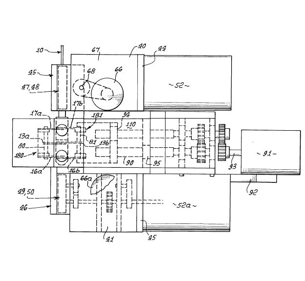
Referring now to Fig~. 2-8, one form of
apparatus to accomplish the above operations (Figs. la-
-lf) is shown in detail. A frame i~ provided, as at
-- 11 --
205444.5
40-44 and 44a, to mount two conveyors 45 and 46, whlch
may be consldered as included within the wire drives 30
and 31, as mentioned. Such conveyors may include two
rearwardly positioned endless belts 47 and 48, and two
forwardly positioned endless belts 49 and 50. The
bel~s provide stretches, as at 47' and 48', which are
adapted to sidewise flatly grip the wire 10 (and
specifically the wlre rearward section lOb) for endwise
advancement and retractlon, as during 6eparation of the
sections lOa and 10_ in Fig. lct and stretches 49' and
50' are adapted to sidewise grip the wire 10 ~and
specifically the wire forward sectlon lOa) for endwlse
advancement and retraction.
The belts 47 and 48 are driven to advance or
retract the wire section lOa as from a drive motor 52
(see Fig. 4). The output shaft 53 of the motor drlves
belt 54, as via a pulley 55, and belt 54 drives shafts
56 and 57. Shaft 56 drlves another shaft 58, through
gearing 59 and 60, to drive shaft 58 and upper conveyor
belt 47 clockwise; whereas lower shaft 57 and lower
belt 48 are drlven counterclockwise in Fig. 2. This
drives the wire forwardly: whereas when motor 52 is
reversed, the wire is driven rearwardly. Additional
axles or shafts for the conveyor belts 47 and 48 appear
at 58a and 57a.
Fig. 2 shows conveyor rotor~ 60 and Cl, and
62 and 63. These carry the belts 47 and 48. Axles 58a
and 57a are driven by drive belts 64 and 65 extending
between pulleys on th~ shaft~ 58 and 58a, and 57 and
57a, as ~hown. Accordingly, when the belt stretches
- 12 -
20544~5
47~ and 48' are closed aga~nst opposlte sides of the
wire 10, and the motor 52 is operating, the wire is
displaced endwise.
Means is provlded to move the conveyor belt
stretches 47' and 48' toward one another to clutch the
wire, and away from one another to de-clutch the wire.
See for example in Fig~. 3-5 the motor or drive 66
carried by a frame part 67 to rotate a vertical screw
shaft 68, as via motor output shaft 69, pulley 70, belt
71, and pulley 72 on the screw shaft 68. The screw
shaft has screw thread engagement at 33 and 34 with
frame members 75 and 76. Frame member 76 supports the
ends of ~hafts 58 and 58a, via member extension 76a, as
at 58' and 58a's whereas frame member 75 supports the
ends of shafts 57 and 57a, via member extenslon 75a, as
at 57' and 57a'. Screw threading interfit at 74 is
oppositely "handed" relative to threading interfit at
73, 80 that when shaft 68 is rotated in one direction
about its axis, the frame members 75 and 76 are
displaced toward one another, whereby conveyor
stretches 47' and 48' may clamp the wire~ and when the
shaft 68 is rotated ln the opposlte dlrection about its
axls, the members 75 and 76 are displaced away from
each other, and the wire i8 de-clutched.
The bearlng supports at 80 and 81 for shafts
58 and 57 are made loose enough to accommodate such
up/down movement of those shafts at the conveyor belt
drlve locations. Note also couplings at 110 and 111.
Tension springs 90 and 91 are provided (see
Fig. 5) between fixed ~ramQ structurQ 92 and shoulders
- 13 -
20544~5
76a' on 76a to yleldably urge the structures 76 and
76a, and the belt stretch 47' downwardly; and
similarly, tension 6prings 93 and 94 are provided
between fixed frame structure 95 and 6houlder 75a' on
75 to yieldably urge the ~tructure 75 and 75a and the
belt 6tretch 48' upwardly. This provides clearance
"take-up" for better control of wire gripping or
clamping.
The forward conveyor unit 46 embodies
conveyor belt drive and up/down movement the same as
described in connection with unit 45 in Figs. 3-5.
The drive motor 52a for driving the belt stretches 49'
and 50' forwardly and re~ersely is seen in Fig. 3, as
is the motor 66a to control belt clamping of the
forward wire section. Mechanism between the motors 52a
and 66a, and the respective forward conveyor belts 49
and 50, i8 the same as above described rechAn~
between motors 52 and 66 and the respectlvQ rearward
conveyor belts 47 and 48; however, the motors 52 and
51a are typically operated simultaneously, either to
drive the wire or wire 6ections forwardly, as in Figs.
la and lf, or to drive the wire sections endwi~e
oppositely, as in Figs. lc and le. A master control to
control all drives, in a pre-programmed manner, is 6een
at 125.
Referring to Fig. 11, the wire severing
blades 13a and 13_ are fully laterally retracted, as
are the wire sheathing stripping blade~ 16a and 16_.
Blades 17a and 17b are in axial alignment with blades
16a and 16_, and are not shown. Note V-angled blade
- 14 -
205444!.~
edges 13a' and 13a " , and blade edges 13_' and 13k".
The blades 13a, 16a and 17a at one side of the wire 10
are lnterconnected by axially extending carrier rod 80;
and the blades 13_, l6k and 17_ at the opposite ends of
the wire are interconnected by axially extending
carrier rod 81, laterally spaced from rod 80. Rods 80
and 81 are relatively movable laterally toward one
another to effect wire severing, as by blades 13a and
13k (see Fig. 9 and also Fig. 1_). Rods 80 and 81 are
further laterally movable toward one another to effect
penetration of the blade edges 16a' and 16a " , and 16b'
and 16_ll into the sheathing (as in Figs. 10 and lOa),
and as also seen in Fig. 1 . Thereafter, the wire
forward and rearward sectlons 10~ and 10_ are separated
as in Fig. le to endwise strip the slugs lOaa and lObb,
off the wire cores, as also seen in Fig. 11. Dropping
of the 61ug is also seen in Fig. 11, as is lowering of
a wire guide lower sector B of guide llb " , to release
the slug. The upper guide sector is shown at A. A
drive 130 is operable to lower and raise ~ector B
Means to effect the described lateral
movement of the blade carrier rods 80 and 81 in shown
in Figs. 3, and 6-8. As seen, a laterally extending
lead screw 90 is rotatable by a drive motor 91, carried
by frame part 92. See connecting shaft 93. As screw
90 rotates in one direction about its axis 90a, nuts 94
and 95 on the screw threads travsl axially oppositely
(see arrows 96 and 97) to move rod 80 to the right and
rod 81 to the left, as in Fig~. g and 10. See
connectors 98 and 99 connecting nut 94 with rod 81, and
- lS -
20544~5
connectors 100 and 101 connecting nut 95 with rod 80.
A pair of parallel lead screws 90 may be utilized for
these purpo6es, as see in Fig. 8, each driven by the
motor 91, with one lead screw associated with blades
16a and 16b, and the other as60ciated with blades 17a
and 17b. Balanced force transmission to the two sets
of blades is thereby effected. See also frame elements
110-116 supporting the structure, as indicated.
Bearings appear at 117 and 118. An additional tubular
wire guide i8 seen at 119.
- 16 -