Note: Descriptions are shown in the official language in which they were submitted.
2 ~;,3
This invention refers to a .~arety system, and
more particularly, to a li rc - saving a I ;l 1'111 I~or pcrsol-s in a
water medium.
~ ven morc palticularly, il is one objc~t of this
invention to provicle an immersion alarm (or an immersion sensor)
intended to save thc life of pcrsons, eit]ler children or invalids
who accidentally fall into the water, alld even persons practising
water sports or swimmers in an emergency situation.
The invention refers to a protective elemcnt to be
used mainly by those persons W}10 are not able to swim in case
they fall into the water by accident or are totally or partially
unable to make thc minimum nccessary movcllle]lts to keep floating.
At the same time, the said protective element allows
these persons to be in the watcr plavin or amusinF themselves
without anv risk to their lives. Likewise, said element can be
used by persons who, even when they can swim, can find themselves
in a dangerous situation (cramps, tireness, water-stream pulling,
injury, etc.).
In brief, the above-referred invention comprises an
alarm means attached to the body of the user in the form of a
necklace, belt, wrist strap, ctc. Said alarm means is activated
when in contact with water, an~ said c;rcumstance -together with
alternatives hereinafter refcrred to- callscs a signal to be
emitted.
The inyention is completed Wit]l at least an apparatus
.
, ~
2~J~ ~32 2.-
receiving said signa]., ~ihicll should bc located with:in a suitablesensing range, so that, wllen tl-e reccivcr senses said signal,
it means that the immcrsion in ~Yater o~ tl~e person equipped
Wit]l the alar~ eans ll~s bcen ~Ictectc~ d, consc~luelltly,
an alert is given on tllis emergency s:ituation. In such case,
the receiver in turn activates a SOUlld (or other)alarm device
located at a place where help can be g:iven to the person in
emergency.
It can also be stated tllat the presence of children
at the seaside, or in rivers, ponds, as well as in swimmin-
pools or any other water medium, has al~ays been a source of
constant worry ancl anxicty to tl~eir l-alellts, cons:icleri.llg tlle
large number of deaths ancl accidents related to asphyxia by
immersion, especially affecting all ch:ilclrc?n who cannot sw.im.
Regarding the use of electronic media to detect
and prevent acuatic accidents produced by asphyxia by immersion,
even if there are some antecedents, up to now they have given
poor results. ~hy? Because the scarce systems developed until
present time, have not succeeded in solving, as yet, aspects
of fundamental importance for an efrective safeguard of the
physical integrity of persons.
Tllis is mainly due to tlle l~act tha-t thc methods or
elements used lack three basic requiremellts: reliability,
practicity and simple installat:ion. I~or said reason, the use
of the same has not attained d:ir~usion or thc samc have failed,
since all. existing apparatus cleserve SCIiOUs object:iolls.
s
z
Such is the case Or a patent registered more than
seventeen years ago, which was unsucces-;rul, precisely due to
its signi~icant technical and structural de~iciencies. We
specifically rcfer to tlle "Licb" patcn~ tl~at, in its practical
implementation, encountered defects J whlch could really not
be overcome.
We shall below mention the main objections we find
against the "Lieb" patent:
1. It is inspired in the emission of ultrasonic signals
or waves, and on account of said signals being extremely
directional, the transmitter, supposedly placed on the chest
of the user, should be directcd to or "~limillg't directly
towards the receiver installed somewhere in the poo~. Conse-
quently, it appears absurd to think that a person who is
drowning will keep still in the water during the emergency and
that, simultaneously, his signal transmitting apparatus will
be exactly "aiming" at the element meant for receiving the
slgnal.
2. So that the ultrasonic signal transmitter described in
the "Lieb" patent had the power and range necessary fo fulfill
its functions in a pool of ordinary size, as for instance a
pool of 4 m x 5 m, it should have an ultrasonic transducer and
batteries of big size. In order to realize the lack of practi-
.i~,; .
city or the non-viability of tl-e "Lieb" patent in this respect,
we should imagine a child, equipped with a transmitter with
.
~0~3~32 4.-
the described elements: it would be something so bulky and soheavy, as if }lC carrie~d, hanging ~rom llis l-eck, an al~paratus
similar to the battery of a car.
3. The "Lieb" patent is restricted, c~clusively, ror use
in swimming pools. That is, it has not been mean~ for use in
the sea, rivers, lakes or any other water medium.
To date, such accidents were mostly preveJlted by
a simple permanent visual control on small children, which,
obviously constitutes a highly unsafe l~recaution.
On the other hand, in crowded places of acuatic
amusement and entertainment, an additional control is usually
implemented by means Or lifc~llald~ OWCVCI~ since such control
is also a visual one, it is as unsafe and subject to failure
as the previous one.
Another widely implemented alternative has been
that comprising the use of life-jackets or belts. I-~owever,
children usually refuse to wear them as said life-saving
devices limit their movements and, in addition, they are rather
uncomfortable when wet. For said reason, children often take
off said life-jackets or belts without their parents noticing
said circumstance, and thus remaining w]lolly unprotected.
~ or the particular case Or swimmillg-pools -and the
prevention of accidents by immersion therein-, there are other
methods which have not been yet referred to but whic}l shall
be described hereinafter so as to show disadvantages involved
2 ~
by their use. Such methocls include pelimetral fences, a
certain kind of protecting ences, as well as se-veral kinds
of coverings or nets. Set forth below are only some of the
drawbacks found in such arrangements:
~a) Lt is for children a real amuselllent or "aclventure" to
climb or overcome such obstacles.
(b) Children can pass over such fences with the uncautious
~` cooperation of other children.
~c) ~y careleness or negligence of a user, the door on the
fence for accessing the pool can be left open.
(d) People coming in or out of the l~ater can get injured
; -as being bare-footed- when stepping oll the means O r engagement
or anchoring of such fences.
: (e) Said protective means tend to cast slladows on the
solarium itself and, in addition, they lack any aesthetics.
(f) An annoying discrimination is made between those children
`;~ who can remain in the pool and those wllo, for being unable toswim, watch the others play from behind the fence.
It is to be noted that existing prevention systems
made it difficult and even impossible to determine if someone
c is immersed in the water and urgently needs help in such an
emergency. Consecluelltly, it can be s;~ at nolle ol the know
methods allow non-swimmers to enjoy their healthy acuatic
entertainment or refreshing bath ~ithol~t any fear or risk,
either they are in the sea, river, ]akes, pools, etc.
".'
. .'
.~ '
.. ~ .
6 -
On the other hand, as it is widely known, death
by immersion also aEfects old people all~l even expert swimmcrs
in critical situation sucl- as on account of cramps, water
stream pulling, physical tireness, etc., accidents which can
not only accur in seas and rivers but also in lakes and
swimming-pools. Think only o the number of lives that could
have been saved, should said people have been able to receive
immediate assistance in the emergency.
As a result, the invention described in this
specification provides an ingenious and effective solution to
the above referred problems and allows the presence of children
near seas, riversg ponds, swimming-pools or any wa-ter medium,
all that without any annoying discrimination and noticeably
decreasing the risks of any accidents caused by asphyxia by
immersion.
Therefore, the invention herein contained solves
the above referred difficulties, on the basis of an alarm
means which, once attached to the body of the user (e.g. a
child~, either in the form of a necklace, belt, etc. allows
parents to be on the alert as soon as the child enters the
water, or either, if desired, the child is allowed to remain
in the water as long as immcrsion ~ocs l-ot cxcecd thc ncck.
Furthermore, and as above indicated, in the case of swimmers
facing critical situations as above indic.lted, they can press
a switch to activ~te the alarm.
`.
2~; 3?
'
Said alarm means consists o r an immcrsion sensor
connected to a transmitter of a remote s;gnal which~ through
distance and when said sensor comes in~o contact with water,
emits a signal activating the alarm. Illus, it is possible to
immediately know when the person to l~hoJn the ~evice llas been
attached to has entered the water or h15 accidental]y allen
thereinto, and also to have enough time to take the necessary
steps to save said person ~either in the sea, river, swimming-
pool, etc.).
For the case of an elderly person or a swimmer in
emergency, the system is not automatically activated, but by
means of a release device, a pusll button, ctc., when necessary.
This invention has also ingeniously solved other
troublesonle aspects:
(a) The receiving means (or the transmitter, as desired)
.
comprises a device which function is preventing the alarm
operation by meTe water splashing or a brief immersion ~only
after some seconds the alarm is operated and new warning
elements are subsequently activated).
(b) This invention can be used in wide water spaces (sea,
river, etc.) without that implying the need of enlarging the
size of the rcmotc signal transmitter (i~t is to bc noted that,
as being attached to the user's body, said remote signal
transmitter should necessarily be small and easy to carry, as
well as an aesthetic element).
~:. ~ , ' '' '' ' .
2 ~ 3 i~
~ or the abo~e-reEerred reasons, for use in large
water spaces or wide distances, the irlvention additionally
comprises a perimetral antenna, one or more buoys, or the
arrangement oF posts,piles, rock fills, walls, etc., equipped
with Tepeaters, so that the latter reccive the signals from
eventual txansmitters and re-transmit the same with greater
strength and at longer range.
On the other hand, in highly crowded places (such
as beaches or water ~ediums of regular extellt), it is not
suficient to receiYe the corresponding signal of alert and
so learn that a peTson among the number of people present
tfiere is in an emergency situation on account of water immersion.
Then, it becomes mandatory to also deterllline the exact location
of said person in the water, so as to immediate help him/her.
T~erefore, the exact location oF the person in danger in highly
crowded places is determined by the use oF a monitor or computer
lnterface which, by means of radiogonometry or triangulation of
buoys or receivers disposed in said posts, piles, rock fills,
walIs, etc., accuratelv detects the place where a life shoul~
be saved.
For all the above reasons, it becomes easy to imagine
the de~ree o~ accc~tancc this systcm l~i`ll havc OIICC takcn -into
,
~ractice, re~ardless of the catePorv or llSC the same maY then
haYe, and considering that, on account Or the characteristics
defining the same, it can either be usecl by children, old pebple
::
:
.
.
.
3 ~
or invalids, and even by grown-ups and expert swimmers, both
in summer resorts ancl in countrics, cl~ s, E.lrms alld weck-cnd
houses, including home and, in ~eneral any l~lace in which
said ~ersons can acc:idcntally ~all illtO ~llC watcr or be ;n
any emergency situation within a water medium which can put
his/her life in danger.
For the above described purposes, this invention
comprises an alarm system for detecting persons who are
accidentally immersed in the water or are eventually in the
water in a situation requiring help, W]l:iCh comprises a
transmitter means which emits a signal including a means for
activating said transmitter mcans whicll :is scnsitivc to a
pre-determined condition, said transmitter means being attached
to the user's body by removable means of attachment and, at
least one receiver means for receiving said signal and capable
of identifying said signal and operate an alarm device arranged
at the place where help is needed.
Drawings
For a better clarity and understanding of the
object o this invention, the same is illustrated by means of
several figures, in which one preferred :Eorm of embodiment
is represented as an example, though not limited thereto,
wherein:
Figure 1 is a block di.ll~r.~ ich csse~ lly
~S
.:
.
.
:~
~`
~3~3~
10 . - ,
shows the circuit forming the liEe-saving device, both regard-
ing means for producing the alarm signal and those intendcd
to receive and amplify said signal.
Figurc 2 illustratcs the ci ICUit oE the means for
transmitting the remote signal.
Figure 3 shows a diagram of the signal receiving
circùit.
Figure 4 is a perspective view of an open ring
showing the life-saving means both as to the general structure
thereof and the arrangement of the different parts and elements
forming said means.
Iigure 5 is a vicw of tllc SalllC ring as closed and
attached to a child's neck.
Figure 6 is an schematic view of an arrangement
whereby the location of the means transmitting the remote
signal can be also located within a large water medium.
Figure 7 shows a block diagram of the circuit of
another form of embodiment of Figure 6.
Figure 8 shows another form of embodiment which
is a plane view of a swimming-pool surrounded by a perimetral
antenna, which communicates to a central receiver connected to
the alarm means. It is made clear that the use of such perim-
etral antenna is advisable only for the case of extraordinarily
large swimming pools. For swimming-pools of ordinary dimensions,
the power of the transmitter will be surEicient by itself to
~ ,
' '' , ~ ' '
.~
.
2 ~
be received by the antenna of the rece:iver.
'1he alarm clcv;.cc Or th;s invclltiotl cssclltia:1ly
consists of a transmitter means 20, Or a U111 or Vllll modulated
high frequency remote signa], WlliC]I :i]l t~lrJI comprises an
activating means 23 for activating saicl transmitter meansl which
is carried by the user on a holder elemc7lt 24, The referred
system is completed by a receiver means 21 for receiving the
signal emitted by the transmitter means 20, w11en activated by
the activating means 23, said receiver means 21 being connected
to an alarm devi.ce 25 which is operated when the receiver means
21 receives the signal from said transmitter means 20.
Said receiYcr means 21 :is alr.~ cd at a .fixcd placc
remote from said transmitter means 20. Said signal tra.nsmitter
means 20 as shown in Figure 2 compriscs a 1.:ig11 frequcncy sta~e
formed by a high frequency N-P-N transistor TRI connected to
the tuned circuit formed bY LI and CVI, CVI bein~ variable
in order to fix the frequency.
In series with the collector-emitter path of
transistor TRI, there is a resistor RI w}1ich limits the current
and is connected to ~round.
Between power supPly and the base of transistor TRI,
there is a bias rcsistor R2, and bctwccll sa:i(l tral1sistor basc
and the tuned circuit there is a feedback capacitor CI.
The choke ZI connected to tl)c tulled circuit output
attenuates the radio frequency flow to thc power supply, and
. .
' - `~. , , ' ,
" '' '`` " `
~0~ 12 -
the capacitor CZ limits the radio-requency existing in the
emitter of TRI.
1he modulation frequency is received at the base
of transistor TRI through diode DI.
The low-frequency stage generating the information
to be modulated comprises the integrated circuit ICI which
ground-connects the output of contact l7 according to a code
established by a combination of groul1d-cor111ecting contacts l
to 12 of ICI in a predetermined manner.
In a preferred form of embodiment of this invention,
the integrated circuit ICI is ~1~153200N.
During the time in l~hic1~ pulls the DI tension
to positive and in consequence the TRI base, the oscillator is
deblocked and emits a series of carrier waves during said period.
Contact 13 of ICI constitutes the input of the
local oscillator of the integrated circuit, which is connected
to the RC~network formed by R3 and C3 and which fixes the clock
frequency of the low frequency stage.
The LED diode DLI, further to operating as resist-
ance to adjust the feeding tension, is also useful for detecting
the correct operation of the signal transmitter, since, wheD
activating mca11s 30 is close~, sets t1lc al1o~le to t]1C sup1ly
positiYe tension, and the diode DLI flashes with ti1e power supply i
voltage.
Apart from being part of t1~e tuned circuit, coil LI
operate. as transmitting antenna, ~hercby the s1gna1 transm1tter
.~ `
.~ .
13.-
~as highly reduced dimens:ions.
~ lc si.gllal rCCCiV:illg IllCilllS 21 is SllOWIl iJI morc
detail in Figure 3, wllicll illustrates ~ circuit diagram thcr~ofthe operation o:L whicll is as hcreinal~cl described.
The signal coming from the antenna ANT is received
at the b.ase of txansistor Tl~10 after passing throug}l capacitor
C12, both.forming, together with the tuned circuit L10-CV10 and
network R10-D10 and R14 the base biasing of transistor TR10, a
su~e~leaction type receiYer.
Capacitors C13 and C14 and choke Zl determine the
reaction .frequence for detecting thc sigl~
lhis d(tectcd l'C~I s.i.gna:l, OIlCc f.i:ltercd I)y the low-
pass filter formed by R13, C15 and C16, whic}l eliminates the
h~gh.~requencY component of the signal ~hich lS then amplified
b.y~TR12~ which together with low resistance R16 and base
polaxization resistance R17, constitutes a hig}l-gain amplifier.
The signal filtered by capacitor C17 is then
ampliied by transistor TR13 whic}l is connected to the emitter
res.i~tor R21 which limits the capacity o-f the amplifier. Pass-
b.and clipping capacitor Cl9 is further connected to the collector
and to the base of transistor TR13.
The output ol this amplifyillg stage is coupled with
t~e base o.~ transistor TR14, by means ol capacitor C20 and
diode D15, once the signal has been dosified by means of diode
D12 and filtered by capacitor C21.
.'`' `
.
. :` ''`' ' '
: ` '
.
.
14.-
',
The following stage comprises a Schmitt trigger,which is formed by transistors ~ and 11~15 and whicll switch-
ing threshold is determined by resistor R27.
A square s:igllal is cmitted Erolll the lRl5 receiver,
said signal being almost with no deformation and is applied on
contact 16 of integrated circuit IC2 to be recognised.
Said PCM signal is compared at IC2 with the shape
of the signal which -once previously programmed- is memory-
stored and, in case of coincidence, conl1ect to ground contact
17 of IC2.
Once ground-connected, the base oE PNP transistor
TRl6, as connected to contact 17 of lC2 by resistor R29, operatesthe transistor and biases the base of transistor TRl7, which is
connected to the divider formed by resistors R22 and R32 thus
saturating said transistor and activating the coil of relay
RLl~ closing contacts C-B and connecting supply to transducer
Bo that emits the alarm sound.
The portion of the circuit appearing at the tope is
a conventional stabilized continuous current power supply
circuit included only as reference for the case in which the
circuit is connected to a 12V battery and, therefore, need
` not to be hereln described.
Activating means 23 is formed in this embodiment
by two electrodes referred to with numbcr 30 in Figure 2, and
;~; which close the circuit when immersed in water.
~ In order to improve sensiti~ity of the immersion
,.
:
. .
sensor, an amplifying stage can be included between electrodes
30 and the circui.t ree(li]lg.
Similarly, a circuit for colltrolling tlle act:ivating
means can be includeLl7 W}liC]l allows detcctirlg a temporary
closure o-~ the c:ircuit activated by electrodes 30, so as to
- avoid the operation of the alarm by tlle mere splash or by onlya brief immersion. Said control circuit is not herein illustrat-
ed for being widely known in the art.
The sound alarm device 25 connected to receiver
means 21 for receiving tlle remote signa:l, is formed by an
acoustic transducer, as referred to as Bo in F:igure 3.
T}lc alarm dcvicc 25 can bc o r l,rogressivc inteJ-Sity.
For the operation o~ tlle alarm system of the present
invention, the holder element 24 is attacheLl.to the user, either
by the neck, waist or ankle, etc., depending on whether the
same is expected to operate whe]l the uscr just enters the water
. (ankle~, the water level exceeds a particular limit (waist) or
when the water reaches a level of total prohibition or danger
(neck~.
ReceiveT means 21 for receiv:ing the remote signal
is arranged near the water medium, so tllat when the user
carrying tlle rcmotc s:igna] translllittcr Inc.llls 20 c]ltcrs thc
water and the acti.vating means Z3 is bclo~ the surface o-f
said water meLl:i.um, the samc is activatcd, .lllLl thL respective
signal is recelvod by tlle antc~ a, a~ld tl~on alllp:LiLicd, thus
~'' .
. . ' : '~
.
:'
`
?-
activating the alarm device 25 which ;.nd:icates that the useris in the water medium with the act;.vat;ng means Z3 bclow the
water sur~acc, said alarm ~evice 25 consc~luently warning the
persons in charge of the respective control and surveillance
so that they can assist the person in ~In cmergency situation.
In the above-clescribed particular case, as the
remote signal transmitter 20 is a Ul-IF or VH~ high-frequency
system, a modulation frequency for multiple users can be
designed, as consistentwith different kincls of alarms, so that
it will be possible to determine which of the users is the one
in the water medium with the activatin~ means 23 below the
water surface. This is due to the fact that the integrated
circuits applied to the signal transmitter means 20 and to the
signal receiver means 21 can be programllled.
The form of embodiment illustrated in Figure 8
comprises the possibility of having the antenna of the remote
signal receiver means 21 formed by a frame antenna 31
perimetrically disposed with respect to the water medium or
pool 32. Such a perimetral antenna allows the reception of the
" . remote signal from a very distant place from the site where
- the emergency occurs. It is to be noted that the preferred
orm of embodiment of this invention is based on the emission
of UHF or VHF requency signals.
~; Another form of embodimeTIt Or this alarm system
is ill.ustrated in Figure 6 and 7, and allows detecting and
. .
`:
2 ~
17.-
locating a user carryinK the remote signal transmitter means20 when said user is in the water medillln, such as sea, rivcr
or lake.
~ igure (~ shows an .Irrangclnc~ y means of which
the location o~ tile user carryillg thc rcmote signal transmitter
20 can also be detected, especially when ~le water medium
concerned is of great dimensions, such as sea, river, lake,
etc.
For this purpose, buoys 33, 34 and 35 are arranged
in the water medium 32, said buoys comprising repeater stations
which emit signals which are recei-ved ~t the coast 36 by the
receiver means 21 having a circuit whicil, in addition to
cmitting thc allrln sign;ll, it ;liso ;I~tiv;ltcs thc mollitor Or
computer interface 37 in which alarm 33', 34' and 35' is
operated according ~o the buoys emitting the signal.
lhe remote signal transmitter means 20, which is
attached to the user's body, effects a low-power transmission
due to the reduced size thereo~ and its signal is received at
a higher degree by the repeater station of the nearestbuoy.
For the case in which the nearer repeater station
is one of the bouys 33, 34 and 35, it will re-transmit the
signal noticeably increasing its power and range and also at
a different frequency.
Figure 7 shows a remote signal transmitter means
20 with an activating means 23 ~hich activates said means, and
, . . .
~,, .
`'~
,
. .,
.
by means of antenna 42, it transmits thc codified signal which
is receive~ by antenna 43 in the nearest huoy having a receiver
means 22 similar to that shown in Figure 3.
I`his receiver means 22 is fcd by a feeding battery
45, which is in turn connected to a battery charger 46 for the
automatic recharge thereof.
When the receiver means 22 receives the codified
signal, the transmitter-repeater 47 is activated, which, in
turn, and by means of antenna 48, emits a wider-range signal
which is received by antenna 49 of the receiver means 21, this
receiver means being connected to the monitor device 37 of
Figures 6 and 7 which, by thc soun~l tlalls(lucct and tllc nssociat
ed screen, indicates which is the buoy cmitting the signal.
Among the different embodiments of this invention,
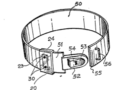
the holder element 24 for the transmitter means 20 is formed by
a band S0 of fixed or adjustable length, which free end includes
a closure device formed by a tapered case 52 which in its upper
part carries a lug 53 projecting above the upper surface of said
case 52, said lug 53 being arranged in a retractile position
with respect to case 52 and comprising a locking system by means
of a key which can be inserted by opening 54.
The system is complctcd at thc other encl 55 of band
50 by a bridge 56, which allows the passage of case 52 by press
ing lug 53 inside the said case 52 until passing bridge 56, the
lug 53 being locked ~hen returning to its initial position out-
'
.
",; .
2 0 ;~ 3 ?,
19.-
side case 52. Said locking system preverlts the pressure of lug53, which can only be unlocked by the corresponding key, in case
the user is a chil-l.
Band so can be Eixed at any part o~ thc user's body,
such as by the ankle "~aist, arm or ncc~, and has the transmitter
means 20 attached thereto with electrodes 30 of activating means
23 exposed, so that, l~hen in contact with water, the circuit is
closed and the remote signal transmitter means 20 is activated.
Activating means 23 of the remote signal transmitter
means 20 can have variations regarding the above described
pattern, since electrodes 30 can be covered by a water-proofing
adhesive tape, so that the activating means 23 can be immersed
in water and is only activated wllell tllC use~ rcmoves said adhesive
tape and closes the circuit by electrodcs 30coming into contact
with water.
Another alternative use of this invention byswimmers
consists in placing the activating means 23 in a watertight case,
i ~"
with a swltcher operated by pressure through a flexible wall of
said watertight case.
,
`: :
,
:
,
.
''.~
'~
. .
`~:
i ` `
~`
,.~
.