Note: Descriptions are shown in the official language in which they were submitted.
1- 205~577
TITLE OF INVENTION
STRUCrURAL MODULE FOR VEHICLE DOOR
FELD OF INVENTION
This invention relates to structural modules for doors
5 suitable for mounting in vehicles and particularly to structural modules
(hardware cassettes) for carrying the load of the door while providing
protection from side impacts.
BACKGROUND OF THE INVENTION
Side doors of vehicles comprise inner and outer door panels
10 and the hardware accessories secured between the panels. More
recently, intrusion beams have been positioned between the panels to
offer protection from side impacts. Also more recently a modular
approach has been taken with respect to the assembly of the door. In a
joint proposal by the Budd Company Stamping and Frame Division and
15 ITT Automotive a modular door hardware plate assembly was proposed
which is pre-assembled with the hardware and pre-tested before
assembly into the door. The heart of the modular assembly proposal is
a stamped module plate which purportedly locates and supports all
internal door hardware. The stamped plated assembly with
20 components is then assembled to the door. The plate alone however is
not sufficient to provide protection from side impact.
Another proposal was made jointly by Bayer AG and
Dynamit Nobel AG of Germany. The basic features of the modular
composite door prototype were an inner steel skeleton structure
25 encapsulated within a polyurethane, and an outer panel made of
polyurea.
The skeleton of the inner panel was proposed to be a welded
steel frame made of rolled sections and stampings. The skeleton is
attached on one side to a hinge plate and on the other to the housing for
30 the latch mechanism. Bent cross-members extend from one side of the
- 2- 205~577
skeleton proximate the housing for the latch mechanism to the other
side of the skeleton. Braces secure the cross-members. The skeleton
does not however provide the primary side impact protection.
It is therefore an object of this invention to provide a
structural module for a vehicle door capable of carrying the load of the
door, preclude sag, and afford protection to passengers riding in a
vehicle from side impact.
Federal Motor Vehicle Safety Standard No. 571.214 specifies
door strength requirements which minimi7.e the safety hazard caused
by intrusion into the passenger compartment in a side impact accident.
This standard specifies 2250 lbs ( 10000 N) as the initial crush
resistance for a side door. The initial crush resistance is defined as the
average force required to deform the door over the initial 6" ( 150 mm)
of the crush. This crush test is performed by a vertical cylindrical
intruder. The load versus displacement curve is plotted while a quasi-
static load is applied to the door by the intruder in an inboard direction
until the intruder travels 6". The integral of the applied load with
respect to the crush distance for 0" to 6" divided by 6 is the average
force in pounds required to deflect the door that distance.
Where an intrusion beam is used in a door, a graph plotted
of force versus displacement provides generally a characteristic curve.
The characteristic curve has three distinct sections. The
curve begins with a linear slope which has been previously established
to be dependent on the geometric bending stiffness of the beams and
their end conditions. This is followed by a sharp change in the slope
(first peak) which is due to the yielding, or more likely, plastic buckling
of the central region of the beam. Finally the curve follows a somewhat
lower slope (virtually flat) in which post buckling deformations occur.
The 6" displacement of the intruder usually includes these three
30 sections. If the test is allowed to continue, the slope of the
- 3 - 205~ 577
characteristic curve will change radically toward a steeper curve and
ends when the beam fails. This final slope is mainly caused by the
membrane stiffness of the tubes.
It is a further object of the invention to provide an
5 improved structural module which is easy to assemble and mount.
Particularly in the past it has been difficult to mount hardware, raise
and lower the window in the door, and still provide protection from side
impact.
Further and other obj ects of the invention will be realized
10 by those skilled in the art from the following summary of the invention
and detailed description of an embodiment thereof.
SUMMARY OF THE INVENTION
According to one aspect of the invention a reinforcing
structure for example a structural module (preferably a hardware
15 cassette) is provided suitable for use in the assembly of a vehicle door,
the reinforcing structure, for example the structural module, comprising
preferably a mounting member (preferably a hinge mounting portion
and in one embodiment a latch mounting portion) and tubes, each tube
having two ends, preferably one end of each tube being connected to
20 the preferred mounting member, preferably when at least three tubes
are used a first tube being connected to the preferred mounting
member and, a pair of laterally spaced tubes preferably extending
substantially in parallel planes and in one embodiment extending in a
substantially parallel direction and preferably connected to the
25 mounting member and preferably to the hinge mounting portion and
preferably spaced from the first tube when at least three tubes are
present. Thus in essence in simple terms the pair of laterally spaced
tubes provide a reinforcing structure for the vehicle door providing
progressive side impact strength.
4 2~54~77
According to another aspect of the invention a structural
module (hardware cassette) is provided suitable for use in the assembly
of a vehicle door, the structural module comprising a latch mounting
member and tubes, each tube having two ends, one end of each tube
5 being connected to the latch mounting member, a first tube connected
to the latch mounting member and, spaced from the first tube, a pair of
laterally spaced tubes preferably extending substantially in parallel
planes and in one embodiment extending in a substantially parallel
direction and connected to the latch mounting member.
According to another aspect of the invention there is
provided a structural module (hardware cassette) suitable for use in the
assembly of a vehicle door, the structural module comprising a latch
mounting member, a pair of door hinge assembly components (a lower
door hinge component and an upper door hinge component) vertically
15 spaced from one another when mounted in a vehicle, and tubes (for
example round 11 /2 " tubes) connecting the hinge components to the
latch mounting member, one tube (upper tube) connecting the upper
hinge component to the latch mounting member and extending
substantially horizontally from the upper hinge component to the latch
20 mounting member when mounted in the vehicle and a pair of laterally
spaced tubes preferably extending substantially in parallel planes and
in one embodiment extending in a substantially parallel direction and
(in one embodiment spaced 3" center to center) connected to the lower
hinge component (for example by welding) and the latch mounting
25 member.
In some embodiments the ends of the pair of the laterally
spaced tubes are flattened prior to being connected to the hinge
components and latch mounting member. The flattening provides
assurance of the necessary deflection required for the correct
30 performance of the structural module. Preferably the ends of the upper
205~577
tube are not flattened for better load transmission as a belt
reinforcement. In another embodiment, the ends of the tubes may be
scalloped (cut on an angle) by conventional methods prior to the tubes
being connected to the hinge components and latch mounting member.
5 Preferably the upper tube is not scalloped. Any method of assuring
providing the deflection of the tubes of the structural module will be
acceptable such as scalloping or flattening as well or any other
geometric weakening of the end of the tube which reduces the section
modulous thereof.
Thus the basis of the design of the preferred structural
module is a substantially triangular arrangement of tubes of closed
cross-section (for example round, square) directly connecting the hinges
to the latch mounting member which is preferably reinforced. In
addition to providing a direct load path to the surrounding pillar
15 structure in the case of a side, frontal, or rearward impact, the
triangular arrangement provides the optimum stiffness for sag loadings.
A longitudinal tube runs from the upper hinge component to
the latch mounting member and acts as an inner belt reinforcement.
Two laterally spaced tubes preferably extending substantially in
20 parallel planes and in one embodiment extending in a substantially
parallel direction (for example round, square) are for example welded
to the lower hinge component and pick up the latch reinforcement at
the rear of the structural module. These tubes may be horizontally
offset or spaced. The offset produces a progressive side impact
25 strength. As the outer tube deflects when a force is applied to it, it
passes the plane of extension and in one embodiment when the spaced
tubes are substantially laterally parallel to one another contacts the
inner tube and produces a compound bending section that continues to
absorb the strain energy at a much higher rate. The wall thickness and
30 diameter of all the tubes can be adjusted individually to produce the
- 6- 2054577
optimum design in terms of the strength to weight ratio of the
structural module. The laterally spaced tubes also allow the window
glass to drop between them.
With the door hinge components, the tubes acting as belt
5 reinforcement and intrusion beams and the latch mounting member are
incorporated into the structural module cassette, and it is possible to
install it on a vehicle or fixture and to operate it as a door. This feature
allows for more flexibility in terms of inner and outer door skin
materials (for example plastic) since all the structural members of the
10 door assembly are contained within the cassette.
All door hardware (window regulator and glass guidance,
latch assembly, inner release handle assembly, lock knob assembly and
door hinge halves) may be pre-installed on the structural module
cassette and adjusted and tested on the cassette. The speaker, window
15 regulator and inner release handle assembly may be carried on a single
stamping, rolled section, plate or the like that is secured (for example
welded) to the inner belt reinforcement (upper tube) and the inner
laterally spaced tube.
A wiring harness for door electrical components including
20 power mirror, window and lock, courtesy lamp and keyless entry
system may be attached directly to the cassette. The door harness may
be connected to the main wiring harness via a modular connector or
connectors .
According to another aspect of the invention a vehicle door
25 may be provided incorporating any of the structural modules as
described. In some embodiments the door frame comprises a forward
shut face carrying slots for the passage of hinge components
therethrough .
The front of the cassette may be loaded into the door frame
30 first and may be netted fore and aft to the inside surface of the door
~ 7 - 2054577
shut face. The forward portion of the window seal/glass guide may
then be positioned between the parallel spaced tubes and may be
secured to the inner tube via an adjustable bracket. The rear of the
cassette may be netted cross car on the rear of the inner panel face.
5 Transverse adjustment of the door assembly is provided by horizontal
slots on the forward shut face of the door frame and an adjustable latch
striker on the B-pillar. Vertical and fore/aft adjustment is provided by
the body half of the door hinges attached to the A-pillar.
The inner trim panel may be attached to the door frame
10 with the armrest attached directly to the inner intrusion tube. An inner
pull handle may be attached to the belt reinforcement tube if required.
BRIEF DESCRIPTION OF THE DRAWINGS
The invention will now be illustrated with respect to the
following drawings illustrating embodiments of the invention in which:
Figure A is a graph of the results of a deflection test of the
Federal Motor Vehicle Safety Standards conducted on a single tube.
Figure B is a schematic view of the deflection of the tube
being tested in Figure A
Figure 1 is a perspective view of a structural module
according to an embodiment of the invention.
Figure 2 is a perspective view of the structural module to
which has been installed operational hardware.
Figure 3 is the modified structural module of Figure 2
installed into a car door.
Figure 4 is a view of part of the door of Figure 3 with
portions removed.
Figures 5 to 10 are close up views of parts of the car door
shown in Figure 3 with portions removed and in Figure 7 showing an
alternative latch mounting member configuration.
- 8 - 2 ~ 5 4 5 7 7
Figure 11 illustrates the deflection of the two spaced tubes
forming part of the structural module of Figure 1 and other similar
embodiments by an applied Force (F) applied to the side of the outer
tube .
Figure 12 illustrates the curve by plotting Force versus
displacement when the specified Force (F) is applied to the side of the
outer tube in Figure 11.
DETAILED DESCRIPTION OF PREFERRED EMBODIMENTS OF THE
INVENTION
Federal Motor Vehicle Safety Standard No. 571.214 specifies
door strength requirements which minimi7.e the safety hazard caused
by intrusion into the passenger compartment in a side impact accident.
This standard specifies 2250 lbs ( 10000 N) as the initial crush
resistance for a side door. The initial crush resistance is defined as the
average force required to deform the door over the initial 6" ( 150 mm)
of thè crush. This crush test is performed by a vertical cylindrical
intruder. The load versus displacement curve is plotted while a quasi-
static load is applied to the door by the intruder in an inboard direction
until the intruder travels 6". The integral of the applied load with
respect to the crush distance for 0" to 6" divided by 6 is the average
force in pounds required to deflect the door that distance.
Where an intrusion beam is used in a door, a graph plotted
of force versus displacement provides generally a characteristic curve.
Please refer to Figure A.
The characteristic curve has three distinct sections. The
curve begins with a linear slope which has been previously established
to be dependent on the geometric bending stiffness of the beams and
their end conditions. This is followed by a sharp change in the slope
(first peak) which is due to the yielding, or more likely, plastic buckling
30 of the central region of the beam. Finally the curve follows a somewhat
- 9 - 2G54577
lower slope (virtually flat) in which post buckling deformations occur.
The 6" displacement of the intruder usually includes these three
sections. If the test is allowed to continue, the slope of the
characteristic curve will change radically toward a steeper curve and
5 ends when the beam fails. This final slope is mainly caused by the
membrane stiffness of the tubes. Figure B illustrates the deflection of a
single tube when deformed by force F and in respect of which the curve
in Figure A applies.
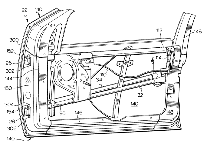
With reference to Figure 1, there is shown structural module
10 20 suitable for use in the assembly of vehicle door 22 (see Figure 3),
structural module 20 comprising latch mounting member 24, a pair of
door hinge components 26, 28 vertically spaced from one another when
mounted on door 22 (lower door hinge component 28 and upper door
hinge component 26) and straight round tubes (11 /2 " diameter) 30, 32,
15 34 directly connecting hinge components 26, 28 to latch mounting
member 24. Tube 30 connects upper hinge component 26 to latch
mounting member 24 and extends substantially horizontally between
the two components when mounted on vehicle door 22. A pair of
laterally spaced preferably parallel tubes 32, 34 (spaced 3" from center
20 to center) connect lower hinge component 28 and latch mounting
member 24. In one embodiment the tubes are parallel in the top view
only but appear to intersect in side view. In other embodiments the
laterally spaced tubes may be oriented to ultimately converge or
diverge but remain effectively laterally spaced between the outer end
25 edges of the vehicle door. To assist with the performance of the
structural module tubes 32 and 34 have their ends flattened and
welded to latch mounting member 24 and to arms 60 and 62 of plate 66
secured to hinge component 28 as shown. The flattening provides
assurance of the necessary deflection required for the correct
30 performance of the structural module. Any other method of assuring
lO- 205~77
providing the deflection of the structural module will be acceptable as
well, such as flattening, scalloping or any other geometric weakening of
the tube ends which reduces the section modulous thereof. Tube 30 has
only one end flattened. This end is connected (welded) to arm 58 of
5 plate 64 secured to hinge component 26 as shown. The other
unflattened end 202 is welded to latch mounting member 24.
Latch mounting member 24 includes plate 40 comprising
two spaced wrap around arms 42 and 44 bent to provide recess 46 for
receiving and mounting latch mechanism 48 (see Figure 4). The ends
10 42A and 44A of the arms 42 and 44 are welded to the ends of tubes 32
and 34. Each of hinge components 26 and 28 comprise brackets 50 and
52 through which pins 54 pass (for connecting to the hinge component
on the A-pillar (not shown) of a vehicle).
As is apparent, structural module 20 is generally triangular
15 in sh-ape. In addition to providing a direct load path to the surrounding
pillar structure of the vehicle (not shown) in the case of a side impact,
this triangular arrangement provides optimum stiffness for sag
loadings.
The two parallel tubes 32, 34 are offset horizontally a
20 distance of 3" center to center. This offset produces a progressive side
impact strength. As the outer tube 34 deflects it in one embodiment as
seen in Figure l l contacts inner tube 32 or in other embodiments
passes the vertical plane of extension of the inner tube without
contacting the tube and produces a compound bending section that
25 continues to absorb the impact strain energy at a much higher rate.
The curve in Figure 12 has the initial characteristics of the curve shown
in Figure A until tube 34 meets tube 32 shown in Figure 11 or passes
the vèrtical plane of extension of the inner tube if the tubes are not
parallel. Thereafter the curve continues with a linear slope dependent
30 on the geometric bending stiffness of the tubes together and their end
- 11 - 2~5~577
conditions (for example flattened, unflattened and scalloped or the like).
This is followed by a change in the slope at secondary yield at 70 which
is due to the yielding or more likely, plastic buckling of the central
regions to the tubes. Finally the curve follows a somewhat lower slope
in which post buckling deformation occurs. Because the area of
rectangle "A" made up by the sides 80 and 82 (see Figure 12) is less
than the areas of "B" & "C" under the curve, the initial crush phase of
government safety standard Federal Motor Vehicle Safety Standard No.
571.214 is satisfied. As best seen in Figure 11 the laterally spaced tubes
may be parallel as seen in Figure 11 or alternatively parallel or
divergènt in the vertical plane but intersecting in side view.
All door hardware may be pre-installed on structural
module cassette 20 (shown in Figure 2). Tube 30 acts as an inner belt
reinforcement. Speaker 90 (see Figure 4), window regulator 92 with
stem 92A to receive a handle (not shown), and inner release handle
assembly 94 are carried on single stamping 96 welded to tube 30 and
tube 32.
A complete wiring harness 100 (see Figure 4) for all
electrical components (including power mirror, window and lock,
courtesy lamp and keyless entry system) is attached directly to the
cassette 20. The door harness 100 is connected to the main wiring
harness 102 in a single modular connector 104. The latch mechanism
48 mounted in recess 46 carries cable 49 leading to the outside release
handle for outside release. Inner release handle assembly 94 is
connected to latch mechanism 48 via cable 110. Lock knob 112 is
attached to latch mechanism 48 by rod 114.
Window regulator 92 carries a glass window which like
regulator 92 is positioned between tubes 32 and 34.
Pre-assembled structural module is then installed into door
22. In this regard (with reference to Figures 3 and 4) door 22
- 12 - 2 0 5 1 5 7 7
comprises outer skin 140, frame components 142, 144, 146 and 148
comprising door shut faces, for example face 150 of component 144.
Face 150 comprises two openings 152 and 154 for passing hinge
components 26 and 28 through the door for connection to hinge
5 components on the A-pillar.
The front of the cassette may be loaded into the door frame
first and may be netted fore and aft to the inside surface of the door
shut face. The forward portion of the window seal/glass guide may
then be positioned between the parallel tubes and is secured to the
10 inner tube 32 via an adjustable bracket 95 (see Figure 3). The rear of
the cassette may be netted cross car on the rear of the inner panel face
148. Transverse adjustment of the door assembly is provided by
horizontal slots 300, 302, 304 and 306 (see Figure 3) on the forward
shut face 150 of the door frame member 144 and an adjustable latch
15 striker (not shown). Vertical and fore/aft adjustment is provided by
the body half of the door hinges (not shown).
With reference to Figures S to 10 inclusive, cross-sections
through door assembly 22 and components of structural module 20
(and a modification thereto) exposing the different cross-sections and
20 door reinforcing portions (shown in dark) are shown.
Particularly with reference to Figures S and 6 structural
reinforcement has been added to the door. In this regard reinforcing
stamped steel "C" section 200 is interposed between door member 148
and the longitudinal unflattened end 202 of tube 30. In this regard the
25 end 202 of tube 30 sits in recess 204 of member 200 and abuts wall
portion 206. Thus any load transmitted along tube 30 is transmitted
into reinforcing section 200 which contacts door member 148 which is
forced into "B" pillar (not shown) in a frontal collision transmitting the
forces into the "B" pillar. Thus section 200 acts as a stiffener. Section
30 200 is connected by a fastener 210 passing through slotted aperture
- 13- 2~54577
212 of latch mounting member 24 and aperture 214 through section
200. A metal tab extending from member 148 extends between latch
mounting member 24 and section 200. Door member 148 is spot
welded to section 200 at the "X"s as at 220 and 222.
Thus by adding stiffener 200 and fastening structural
module 20 thereto, not only is the longitudinal and sag strength of the
door increased, but also side impact load strength.
With reference to Figure 7, structural module 20' is shown
(in part) substantially the same as structural module 20 except that
latch mounting member 24' replaces latch mounting member 24.
Member 24' is broader and stronger.
Figure 8 illustrates the car door 22 partly in section looking
from the outside. Tube 30 supports interior door trim panel 230
attached by a fastener extending under the tube (for example a snap
fastener or clip) as at 237. Window seal 234 is attached to the inner
trim panel 230 by hook portion 236 sandwiched between tube 30 and
inner trim panel 230. Further reinforcement of the door is shown at
238 and 240. Reinforcement 240 reinforces the upper hinge
component 26 in the form of a "C" section welded in the door.
Reinforcement 238 in the form of a "C" section stiffens the window
frame .
With reference to Figure 9, a cut away view of the door,
tube 30 is shown welded to plate assembly 64 to which hinge
component 26 is welded through rectangular openings 246 and 248.
Plate 64 is welded to reinforcement member 240. While in this
embodiment tube 30 is flattened at its end connected to plate assembly
64 prior to welding to plate assembly 64, the tube end may not be
flattened but left round for better transmission of the longitudinal
forces as a result of a frontal or rearward crush.
- 14- 235~577
Figure 10 highlights the upper seal section of the window at
250.
As many changes can be made to the various embodiments
of the invention without departing from the scope of the invention; it is
5 intended that all material contained herein by interpreted as
illustrative of the invention and not in a limiting sense.