Note: Descriptions are shown in the official language in which they were submitted.
- 205~591
WlR~ 5S TELECOMMUNICATION SYSTEM
Technical Field
This invention relates generally to a telrco~ çatir~n system and
more particularly to a wired teleco.--.--..l-ir~tion system that can establish a5 co.~ .-ir~ti~n path between a selected wired co....~ .-iç~tion path and a cordless
~ phQ~
Back~round of the Invention
A wired teleco.n.-.~-iration system such as, for example, a Private
Branch FYrh~nge (PBX) has attracted widespread use for business co.~ ir~tions
10 because of its flexibility of allowing one to design specific services in accordance
with one's business needs. Nevertheless, the e4uip~llellt with which the PBX users
co.--.--v~-irate are tradition~l telephones which are hardwired to the PBX switch.
This undesirably limits the mobility of the user who is tethered by the cord
COIll ec~ g the h~n~set of a telephone to its fixed base-unit. Although the tra~ition~l
15 telephones can be replaced with cordless telephones to increase the mobility, this
repl~cem~nt, however, does not provide a desirable solution because the portableh~n(3set of a cordless telephone must interact with the fixed base unit associated
ll,ede~. illl. This being so, as the ~ t~nce between the portable handset and the base
unit increases, the signals to and from the handset are accordingly atlellua~ed. In
20 ~dition~ ~ignifir~nt interference is caused by the signals from other cordless
telGphQnes which are also connected to the PBX switch. As such, the mobility gained
by using a cordless telephone is not only limited, but also results in a co~ lolllise of
signal quality.
Attempts have been made to solve the above-identified problems. One
25 such attempt involves the use of a pico-cellular co.. ~.nic~tions system such as
described in the publication by D. Akerberg, "Properties of a TDMA Pico CellularOf fice Co.~ ir~tion system," EEE ICC 1989, pages 186-191. In such a system,
fixed base units are connlocted to a centralized system manager to provide a
ll~-sceiving function for the various different pico-cell sites. The system users are
30 supplied with portable h~ndsets which can interact with any one of the fixed base
units. As a mobile handset moves from a pico-cell site of a first base unit to another
pico-cell site of a second base unit, the provision of the transceiving function is
switched from the first to the second base unit under the control of a system
m~n~ger. Although this switching scheme is intended to solve the signal attenuation
35 problem, it does, however, still require relative high tr~n~mi~sion power. The fact
that the tr~n~mitt~l signals contain relatively high power may preclude such system
~ - 2 - 205459 1
from operating in certain radio-frequency bands. Moreover, although this system
manages to eliminate the above-noted interference by using a time-division-multiple-
access (TDMA) scheme (i.e., each portable handset can only transmit and receive signals
5 during its preassigned time slots), the received signals in this system are corrupted by
another type of degradation, namely, multipath distortion. Such distortion occurs when
various mutually delayed version of the signal travel along various paths of different
lengths. Furthermore, to achieve a significant capacity a substantial spectrum allocation
may be required.
Accordingly, a need exists for a wireless telecommunication system which
does not have the above noted defects.
Summary of the Invention
In accordance with one aspect of the invention there is provided a
communications system comprising a transmitter whose transmitting functions are
15 controlled by a first clock signal; a receiver whose receiving functions are controlled by
a second clock signal; clock recovery means connected to said receiver for generating
said second clock signal in response to communications coupled from said transmitter,
said clock recovery means including an oscillator whose operation is varied in response
to said communication; said clock recovery means further including means for
20 substantially maintaining this operation at its last varied state in an absence of any
communications from said transmitter; and said communications between said transmitter
and receiver occurring in bursts and said clock recovery means still further including a
switching element connected to said oscillator, said switching element being selectively
closed during the presence of a burst for coupling said burst to an input port of said
25 oscillator and opened during the absence of said burst for isolating the input port of said
os,cillator.
In accordance with another aspect of the invention there is provided in a
method comprising the steps of providing a wireless signal in bursts from a first to a
second transceiver; recovering a clock signal from said wireless signal at said second
30 transceiver by varying a characteristic of an oscillator in response to said wireless signal
and substantially maintaining the last varied state of the characteristic in the absence of
said wireless signal; using the recovered clock signal to control the reception and
~' .
- 2a - ~ a5~
transmission of communications in said second transceiver; and connecting a switching
element to said oscillator, said switching element being selectively closed during the
presence of a burst for coupling said burst to an input port of said oscillator and opened
during the absence of said burst for isolating the input port of said oscillator.
In accordance with yet another aspect of the invention there is provided a
wireless communications system comprising a wired communications system having aplurality of communications channels; a plurality of non-mobile radio transceivers, each
connected to said wired communications system via a different communications link; at
least one wireless mobile transceiver, each adapted to communicate with each non-
mobile radio transceiver; clock recovery means disposed in each mobile transceiver to
recover a clock signal that is used for controlling transmit and receive operations in that
mobile transceiver, said clock signal being recovered from wireless signal bursts coupled
from said non-mobile transceiver to that mobile transceiver, said clock recovery means
including an oscillator whose operation is varied in response to said bursts and means
for substantially maintaining the operation of said oscillator in its last adjusted state in
the absence of said bursts; and said clock recovery means further including a switching
element connected to said oscillator, said switching element being selectively closed
during the presence of a burst ,for coupling said burst to an input port of said oscillator
and opened during the absence of said burst for isolating the input port of said oscillator.
The preferred form of the present invention overcomes the prior art
limitations by dividing the coverage area into regions, hereinafter referred to as "femto-
cells", that are smaller than pico-cells. The inventive system can be built as an adjunct
to a wired telecommunication system such as a PBX. Advantageously, because of the
relatively small size of a femto-cell, transceivers in the inventive system can use very
low transmission power, compared with the pico-cellular communications system, to
communicate with the fixed transceiver. In addition, because of the relatively short
distance between the mobile handset and the fixed transceiver, the communication paths
between any two transceivers are reduced and, therefore, the multipath distortion which
can affect the received signals is substantially reduced.
-2b- 2954~9 ~
A concomitant problem normally associated with relatively small cells is the
need for a switching system which can accommodate the large amount of switching or
handovers required to accommodate the various mobile units as they move from one cell
to another. In accordance with the present invention, this problem is solved by a
S switching technique which is not centralized in the PBX but, rather, is effectively
distributed among the individual fixed-cell terminals.
Brief Des~ )lion of the Drawin~
Fig. 1 is a block diagram of a Time-Division Duplex digital system in
accordance with the principles of the invention;
Fig. 2 is a block diagram of the fixed radio station of Fig. l;
Fig. 3 is a block diagram of Fig. 1 including structure of the digital router;
Fig. 4 is an illustration of Time-Division Duplex frames; and
205~91
Fig. 5 is a block diagram of a circuit for l~ico~ing a clock pulse from a
burst signal.
Detailed Description
In this invention, a wired teleco....n~ tion system such as, for
S eY~n~ple~ a Private Branch Exch~nge (PBX) is now provided with a wireless
c~p~kility. More specifir~lly~ a PBX is provided with wireless/portable access to
permit a user to roam freely over the area served by the wired PBX system. The
system uses cYi~ting re~lm~nt wiring available in a typical PBX inst~ ti- n to
subdivide the covered area into a number of small cells, typically, one cell per room.
10 Radio and ~witching techniques for this system can result in several benefits such as:
A) Low initial cost for a system with limited coverage/capabilities, with eYr~mion
costs being proportional to the capability being added; B) Simple, FM-based radio
interface which is not impaired by multipath prop~g~tion and, through extensive
rl~uelu;y reuse, providing good system capacity at low cost; and, C) Low power
15 operation that allows the use of the ISM band (902-928 MHz) under Part 15 of the
FCC rules without spread-~ecl~ techniques and with low risk of in~.r~ nce to
or from the system.
The concepl is based on a so-called "femtocellular" arc~itectllre. The
prefix "femto" is the next one down after "pico" and is used to emph~i7~ the fact
20 that the coverage area is subdivided into cells that are even smaller than those for
so-called "pico cellular" systems as proposed in the publication by D. Ak~.l,~ ~entitled "~.lies of a TDMA Pico Cellular Of fice Co..~ tiQn System," 39th
IEEE Veh. Tech. Conf., San Fr~nri~co, CA (May 1988) pp. 18~191. Typically, in
this invention, there are one or more cells per room, and the interc~nnection~ among
25 the various cell sites and the cent~l PBX switch are accomplished through exi~ting
PBX wiring.
In this system, the covered area is subdivided into very small cells, even
smaller than those pl~osed for so-called "picocellular" systems. Thus, the system
here ~i~closed is referred to as a "femtocellular" system. Many existing PBX's have
30 re~hln~l~nt wiring in the walls; typically, there are re~1nd~nt jacks in each room, and
each jack carries four wire pairs, of which only two are used by most terminals.~ddition~lly, these wires can easily support a bit rate of 1-2 Mbit/s. While this may
not be very much as an aggregate bit rate, a femtocellular alchilec~ e would al~w
this bit rate to be re-used many times over the area covered and thus allow the
35 wil~,less adjunct to provide the required capacity. Indeed, since PBX wiring is
available in esseJ-ti~lly every room, a cell can typically be a single room. Because
2034S91
signal prop~tion from room to room is not very good in the average building, thefull S~ ulll can be reused in rooms which are only a few rooms away.
Many illl~l ~nt advantages are brought about by the use of such small
cells. One is the ability to re-use the spectrum many times, as noted above. A
5 second advantage is the elimin~tion of multirath ;~ a;~P~ lltipath ;I~ A;III~I1t
il~cl.,ases substantially as the llict~nre be~ l tr~nsmitter and receiver increases.
While there is great variability of signal tr~nimicsion charactericffrs from site to site,
~lepen~lin~ on construction materials, building design, and the like, for sya~mswhich operate at 1-2 Mbit/s imp~irment becomes si~nifis~nt at ~ict~nces which are
10 greater than a hundred feet. In the femtocell~ r system here ~lisclosed, distances are
typically subst~nti~lly less than a hundred feet, and, therefore, the multipath
;.. p~;.. nt can be ignored. It is here noted that picocellular syslems describe~l by
D. AL,I~; in his article identifiecl above include no provisions for multipath
pl~ ;on (such as equ~li7Ation) even though their operating distances are much
15 closer to the range where it can become a problem. Clearly, the Çellllocell~ r
concepl here disclosed incllldes a comfortable safety margin.
A third advantage of the short ~lict~nses is the very low radio-frequency
(RF) power required for co------~ ic~tion~ In ~ ition to the obvious benefits of lower
cost and reduced power-supply dem~n(l, this has important benefici~l regulatory
20 imrlirationc Speçifir~lly, the fact that there is no ~ecllu~ loc~t~3 by the Federal
~""~ ir~ti~?n C~ommic~ion (FCC) for this type of service, leaves the Industry,
Science and Medical (ISM) band as the only possibility for a digital wireless PBX to
be deployed in the near future. It is here noted that the ISM band (902-928 MHz)has been opened recently for llnlicence~l use under Part 15 of the FCC reg~ tinnc
25 Use of this band would norm~lly carry the requi~ ent that spread-sp~ll um
techniques be used, except if the tr~ncmitte~l RF field can be kept below a certain
limit that cOll~a~llcls to about 1/2 mW of ll~nc.~ ed power. This is quite adequate
to support 1-2 Mbi~/s at the short clist~nres of the femtocelhll~r archi~ cl.~ so that
this invention can operate in this band without the complication of having to use
30 spread ~ l UIll.
A fourth advantage of the small ~lict~nces is the short propagation
delays. At the speed of light, which is approximately 1 ft/ns, the round-trip delay of
the radio signal is always a small fraction of the bit period (which is 500 ns at
2 Mbit/s). Thus, in this invention the system can be completely syllchl~nous, where
35 the same clock is used for both the forward and reverse links (downlink and uplink).
Referring to Fig. 1, there is illustrated structure in accordance with the principles of
20S4591
the invention. It is to be noted that the ~lisclosed system is dirr.,~Gilt from the typical
bile-radio en~h(J.~...f -l, where it is usually desirable to put sophisti~ted
h&~ in the fixed station, (which is shared among many mobiles) if it leads to a
s;tnrlifiratinn in the mobilelh~ndset design. In this invention, the intelli~nce can be
5 in the h~n(l~et and the PBX to allow for simplific~tion of the task of the fixed radio
units.
The very low RF power requirGlllent of l/2 mW means that if the fixed-
radio unit can be kept at a colll~bly low power-supply re(luilGIllent, i.e., less than
lW it may be possible to power the whole unit through the same PBX wire used for10 co~ tion~ This will elimin~te the need for an AC power hookup to the fixed
units.
Important features that this wireless teleco~ c~tion system offers
inclu(1e a) l~o~ming, i.e., the ability for each portable to place and receive calls
anywhere in the coverage area without requiring any special action; b) The ability to
15 have mllltiplP, ~imlllt~nP,oll~ly active users in the same room, their number being
limited by the total capacity available in one frequency re-use; and c) T..~.~-...-ily to
h~t~,r~,~nce from similar systems located in the vicinity.
The short ~ t~nces of the inventive femtocell~ r ~chi~,c~ G are very
helpful, when it comes to intelr~.~nce, in two ways: a) The in~lr~llce caused to20 other ~t,_ms is small because of the low tr~n~mittecl power levels used; and b) The
~ l power levels will be high, despite the low tr~n~mitted levels, and they will
provide a good margin against a possible inlelr~,.ellce background.
The embodiment of the invention disclosed in Fig. 1 is a Time-Division
Duplex (TDD) digital system. It is to be understood, however, that the system can
25 be a rl~uellcy Division Duplex (FDD) digital system. Speçific~lly, three i
~l~,anlages of TDD are: a) Flimin~tion of the need for the costly RF filtPring
~uih~,d by rlG~luency duplexing. b) The same prop~gation mP~lillm, at the same RF
frequency is used, in both directions. (This provides ch~nnel reci~ y which, in
this system, is exploited as follows: At any given tirne, the system picks a specifi~
30 fixed ratio station to co~ -ic~t~ with a given portable. The choice is made in such
a way as to op~ e the quality of the uplink channel. Because of reciprocity, thechoice will also be optimal for the downlink channel); and, c) With TDD,
tr~n~mi~sion and reception occur at different times. Thus, it is possible for some RF
har~wd~e to be used for both purposes, leading to a reduction of colllpo"ellt count.
35 Theoretically, frequency m~~ tion (FM) requires more bandwidth and has higherSignal-t~Noise Ratio (SNR) than, for example, two-level Phase Shift Keying.
- 6 205459 1
However, it has the advantage that it is very simple and economical.
The m~~ tor can be a Voltage Controlled Oscillator (VCO) that puts
out enough power to go directly into the antenna without an RF amplifier. The
~em~ tor can be the Motorola MC13055 which is a low-cost integrated circuit
5 that can handle bit rates up to 2 Mbit/sec. It inrlu~es a limiting IF amplifier with a
dynamic range better than 60 dB and a limiting sensitivity of about - 60 dBm.
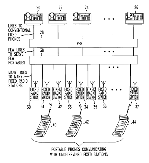
Referring to Fig. 1, a wireless telecommllnir~tion system such as a PBX
can include a plurality of station sets 20, 22, 24, 26 coupled to a PBX switching
center 28 via co~.. l.lication paths such as copper wires. A plurality of fixed radio
st~tion~ 30, 31, 32, 33, 34, 35, 36, 37 are coupled via other commllnic~tion paths
such as copper wires to the switching center 28 ~rough a digital router 38. Portable
phones, typically 40, 42, 44 are adapted to co. . ~ ir~tç collectively, via radio, to
the fixed radio stations 30-37.
Referring to Fig. 2, there is illustrated a block diagram of the fixed radio
station 30-37 of Fig. 1. Of the two halves of the radio link, the portable phone 42-44
and the fixed radio station 30-37, the fixed radio station is the more challenging
because of the constraints discussed in the preYious Section. However, very similar
goals (low power, low cost, small volume, etc.) also apply to the portable unit, so
that many of the same solutions are useful for both.
Referring to Fig. 2, the circuit can comprise four RF components: The
~nt~nn~ 202, the RF filter 204, the b~l~nced rmixer 206 and the fLlced-fre~uency local
oscill~t~-r (LO) 208. All four components are used in both tr~ncmicsion and
reception by taking advantage of the bidirectional capability of the b~l~nceA mixer
206. It is to be noted that the b~l~nce~ mixer is ~csllmed to be a passive mixer.
A bit in port 214 is coupled to an input port of a TDD control 216, an
input port of a flip flop 218, and an input port of a clock generator 220. An output
port of the TDD control 216 is coupled to switches 210 and 212. Output port of flip
flop 218 is coupled to the input port of IF VCO. Switch 212 is coupled to feed asignal through an Il; LNA 222, an IF filter 224, an FM LIM-DISCR 226, and a flipflop 228 to an output port 230. The output port of clock generator 220 is coupled to
flip flop 218 and flip flop 228.
The prinriple of operation of the structure of Fig. 2 is as follows: During
reception, switch 210 is opened and switch 212 is closed, so that a standard
heterodyne receiver is provideA Because there is no RF prearnplifier, the noise
35 figure of the receiver will be reduced by the insertion losses of the mixer and R~;
filter. During ~n~mi~sion, switch 212 is opened, switch 210 is closed and the IF
*Trade mark
7 2054~9 1
VCO, which produces a signal with the desired 2-FSK modulation centered about the
receiver's IF frequency is activated. This signal is inserted into the mixer's IF port.
Because the balanced mixer is bidirectional, this signal will be mixed with the LO signal
from 208 and the RF port of mixer 206 will produce a version of the 2-FSK signal5 unconverted to the desired RF frequency. It will be accompanied by an unwanted mixing
product, as well as by the residual unsuppressed LO signal, both of which are eliminated
by the RF filter 204.
The rest of the block diagram is relatively straightforward. Although the
ports 214, 230 for bits in and bits out are shown as being separate, the architecture insures
10 that they will not be used at the same time; and the two ports can be connected via an
interface to a single wire pair. The only supervisory signal required from the sv~itching
center 28 of Fig. 1 is the "TDD control", which puts the unit in either the transmit or
receive mode. This signal, the information bits, the bit clock etc., can be transmitted over
the wire pair by any one of the many known ways.
The absence of a clock-recovery box for the received signal is to be noted.
This is because the system takes advantage of the very short distance between the fixed
radio station unit and the portable phone, which renders the radio propagation delay
negligible. It is assumed that, in the portable phone unit, the bit clock is recovered from
the received bits using a Phase-Lock Loop (PLL). The PLL is sufficiently stable that it
20 can maintain the correct phase for a period of time, even in the absence of an input signal.
Because of this it can "flywheel" over the portion of the TDD frame where no signal is
received. In this manner, the recovered clock is available in the portable unit during the
entire TDD frame and can be used during transmission to generate the transmitted bits.
Referring to Fig. 5, there is illustrated a block diagram of a circuit for
25 recovering a clock pulse signal from a burst signal. The burst input signal is applied via
an input terminal 502 to a nonlinear device 504 such as a diode or the like. The output of
the nonlinear device is fed to an input port of a multiplier 506. The output of the
multiplier is coupled, through a switch 508 to the input port of a loop filter 510. The loop
filter can comprise an input impedance 512 to an operational amplifier 514 in combination
30 with a feedback loop of a capacitor 516 in series with an impedance 518. The output of
the loop filter is coupled to the input port of a voltage controlled oscillator 520. A
feedback loop 522 couples the output of the voltage controlled oscillator to a second input
port of the multiplier 506. The switch 508 is selectively opened and closed by the burst
signal. The recovered clock pulse signal appears at output port 524.
-8- 295459 1
In operation, at the end of a burst the state of the circuit of Fig. 5, which
can be consi~lered to be a second order phase locked loop (PLL), is "frozen" with the
oscill~tor 520 running freely. If the short-term stability of the oscill~tor is
sllffiriPntly good, the phase error ~cc..m..lQtPA while the oscill~tor "flywheels"
S ~t~. ~n bursts will be small. In the fixed radio station unit, the clock signal comes
through the wire pair. Whether it is recovered from the digital signal or obtained by
some other means, it is available during the entire TDD frame thus pc ...;11;l-~ the
clock to be used for both the tr~n~mitted bits and for l~tching the received bits that
come through the fixed radio station. In Fig. 2, the RF filter 204, in ~d-lition to
10 providing the usual function of limiting in~elrel~nce, helps meet the FCC's out-of-
band emi~sion constraints. Specifically, the FCC requires all emission~ outside of
the ISM band to be ~tt~nn~ted by at least 48 dB with respect to the llnn~ ;tt~ signal
of 1/~ mW. In this invention, out-of-band emission~ can be caused by the LO signal
that leaks through the mixer during both tr~nsmi~sion and reception, as well as by
15 the ull~.~ ~d mixing product during tr~n~mi~ion. Both of these can be ~It~ e~ by the RF filter down to a level that meets FCC requir~;lllF n ts.
If an IF frequency of 40 MHz, is selected, as is recomm~n~ in the
applir~tion notes for the MC13055, then a two- or three-pole RF filter meets thel~ui~ ~nls. With this choice for the IF frequency, the IF filter is realizable with
20 llm~l co~ ol ents.
The large number of small cells here ~isclosed means that handover can
be a co~ n oc~ ce in this system. There are two re4ui~ F nl~ a) Handovers
have to be se~mless; i.e., invisible to the user; and b) Handover control has to be
distributed and require little overhead to prevent the system from becoming
25 o~e~whdmed by the large volume of such events.
Following is a digital-routing architecture that meets these re~ui-c~
To simplify the des~ ion, a system without frequency re-use will be con~i~P,red
first.
Referring to Fig. 3, there is illustrated the structure of Fig. 1 plus the
30 structure of the "DIGITAL ROUTER" box. The digital router can include a
s~ C~ lOUS bus 302. PBX interface units 304, 306, 308, 310 inte.~onnecl the
synchronous bus 302 with discrete co..-,--~ tion paths to the PBX swi~hing
center 28. A Time Division Multiple Access (TDMA) controller 312 is coupled to
each int~rface unit 304-310. A synchronous bus is also coupled to each fixed radio
35 station 30-37 via a radio interfaçe unit 314, 316, 318, 320, 322, 324. The wire pairs
coming from the fixed stations 30-37 are illte,.;onnected via a synchronous bus 302.
205459 1
The bus can include a single data line that is shared among the various fixed radio
station according to the same TDD frame that is implçmpntç(l on the airwaves. The
same clock is used for both. For the downlink, the radio interfa~e units 314-324 take
bits &om the bus and put them on the wire pairs, without any proces~ing or storage.
S Th;e reverse occurs for the uplink. Any processing, tr~n~l~tion~ etc. that is l~uil~,d is
pe.r~. ..~ in the PBX interface units 304-310 and/or in PBX gateway 326 in~.~osed
~t~.~n the PBX il-lF r..ce units and the PBX switching center 28.
In practice, the signal delay over the wire pairs is not negligible. It is,
however, small. In most PBX inst~ tion~ the cable length bel~een a jack and th
10 e~ p~ nt closet which contains the digital router and the PBX switching center is
n-~rn~lly limited to a maximum of 100 meters . This corresponds to a round-trip
delay of less than about 1200 ns which, at a bit rate of 1-2 Mbit/s, corresponds to 2-3
clock cycles. To account for this delay, the uplink portion of the TDD frame on the
bus should be delayed, coll~cd to the radio TDD frame, by an amount equal to the15 ...;~ possible cable delay. Each radio interface unit can include an adjustable
digital delay, which can be set at in~t~ tion time, to insure that the round-trip delay
is the same for all units, regardless of differences in cable lengths.
Referring to Fig. 4, there is illustrated a diagram of the Time Division
Duplex (TDD) frames. The only difference between the upper (in the air) and the
20 lower (on the bus) is the position of the guard space, whose siæ must be equal to the
n. cable round trip. Details such as the bit rate, the nulllber of slots, etc.
depend on the speçifi~s of the system implçm~nt~tion For example, if a
sion bit rate of 1.544 Mbit/s and a voice data rate of 32 Kbit/s, is chosen,
then about 20-22 slot position~ are needed in each half of the TDD frame, where the
25 exact nUmber depends on the amount of overhead ailowed for error plotec!ion, guard
time b~l~n slots, etc. It has been determined that about 20-22 slot positions will
support about twenty siml~lt~neously active wireless users.
Because the entire system is synchronous, no burst preamble is needed
and the guard time belween bursts can be as little as one clock cycle--just enough
30 for the RF output of one tr~nsmitter to die down and that of the next tr~n~mitter to
reach full power. With such a low frame overhead, the frame rate can be kept
relatively high without si~nifi~nt penalty, which is usually desirable. However, the
se1~tion of specific frame parameters will, in general, have to also take into account
non-t~,chni~l factors. For example, it may be desirable to consider the advantages
35 (or lack thereof) of having some compatibility with the Digital European Cordless
Telecr.. -.~t-ir~tion~ (DECI) standard.
20~4~91
- 10-
Each half of the TDD frame contains two dirr~.cnt types of slots,
namely, regular co~ nicption slots 402, 404, 406, 408, 410 and cign~ling slots412. The downlink ci~n~ling slots contain the signaling bursts coming from the
system controller, which pe lÇo~ two important filnctionc: a) They provide the
S downlinlc ci~ling channel from the controller to the portable units; and b) they
provide the frame marker, which the portable units use to ~--cl~unize th~mcelves to
the TDD frame. Unlike the regular downlink bursts, the signaling bursts are
lln~-s~ t~l by all the fixed radio units cim-lltaneously; this insures that all portable
phones (portables) receive the bursts regardless of where they are. The clock- and
10 frame-recovery circuits in the portables should be deci~ned to work plo~.ly when
the only received bursts are the si~n~ling bursts. Thus, it may be desirable to have
two sign~ling slots, one at the beginning and one at the end of the downlink half of
the TDD frame.
The uplink portion of the frame have the counterparts of the regular and
15 sign~ling slots. Rec~use there are many radio interface units 314-324 that can put
data on the bus, a bus-contention scheme is needed to insure that, in a given time
slot, only one unit has control of the bus. This unit should be the one whose
col~ ,onding base station has the best radio path to the portable phone that is
tr~ ;ng in that particular time slot. The uplink and downlink cign~ling ch~nn~lc20 are used during call set-up whether initiated by the PBX or by the portable phone
unit.
Following is a description of how to select which radio interf;~lr,e unit
should take control of the bus during each uplink slot. The principle of operation is
as follows: Each received burst incl~ldes parity bits or, more generally, fol ~ error
25 correction that can be used to establish the quality (number of bit errors) of the
~ ;ved signal. Each radio interface unit monitors the number of errors which occur
in each slot. If no portable phone unit is tr~nsmitting in the vicinity of the
c~ ,s~.-ding fixed station, a large number of errors will occur. Con~,el~ely, in a
slot where a portable phone unit is tran~mitting, some of the radio interfare units will
30 register a small number of errors; those connected to stations that are closer to the
portable will register fewer errors than those further away. All the units conten-l for
the bus, and the one with the fewest number of errors is given control of the bus.
The details of how the contention can be resolved are as follows: The
bus can include a few lines (for example, four lines) dedicated to contention
35 resolution Each of these lines is driven concurrently by all of the radio inle~ r~ce
units in such a way that if any one of the units pulls the voltage down, the voltage
2054~91
will stay down. It will be up only if none of the units pull it down. At each burst,
each unit pulls down a number of lines determined by the number of errors observed:
With no errors, all four lines are pulled down; with a large number of ern~rs no lines
are pulled down; for an i~ ,, ...e~ te number of errors an i.~te...~eAiat~ number of
5 lines are pulled down, in the style of a "the~ ometer" display. Each unit .. .~nilo. ~
how many lines actually go down; if more lines go down than the unit itself pulled
down, it means that there is some other unit on the bus that has a better signal burst.
If the nul~ber of lines that go down is the same as the number that the unit pulled
down, it means that it has the best available signal burst, although there may be
10 others that have an equally good signal. One of these radio intef~ce units will take
control of the bus. Since it doesn't make any diLr~ reilce which one it is, this~mhiguity can be resolved through a priority convention, e.g. the leftm( st such unit
grabs the bus.
The above procedure solves the problem of the uplink. For the
15 downlink the problem of bus co--lenl;on does not exist, however, the unit that has the
best radio path is still desired to transmit the burst. This can be acco~ lished as
follows: When a radio interf~t e unit grabs the bus during an uplink slot, it
f -..~ ~ the slot position. When the corresponding (homologous) downlink slot
comes along, that unit will also have the best downlink path, thanks to the path20 lG~ JCily in TDD systems, and therefore it is the one that tran~mit~ the data. In the
~implest impl~ n~ n, the homologous slot may just be the slot that is in the same
positinn in the downlink half of the TDD frame. If, for some reason, indepen~lent
selecti~n of uplink and downlink slots is required, a mechani~m for the Time-
Division Multiple Access (TDMA) controller to inform the radio interface units of
25 how the slots are paired can be provided.
This scheme provides both distributed handover and a form of ~ntenna
di~ y. That is, a portable unit will usually be within range of a handful of fixed
statinn~ As the multip~th environment changes and the path to the fixed station
being used becoll-es bad, the radio link will alltQm~ti~ ~lly switch over to a dirr~Gn
30 station with a better path. The goal of a distributed, se~mless handover is thus
achieved in a way that is perfectly transparent to the TDMA controller, the PBX and
the PBX interf~e units. All they have to do is put the bits on the bus at the right
time and collect the return bits in the homologous slot; they do not have to know
where the portable unit is or how it is moving. On the other side, the fixed stations
35 do not have to know which portable unit they are co.~ icating with in each slot,
they only have to know the positions of the homologous slots. This is reflected in
2054591
- 12-
Fig. 3 by the ~hsenre of connpction~ from the TDMA controller 312 to the radio
f-.ri"cunits314-324.
In the procedure just described, it is to be noted that there may not be
enough bits in a single burst to obtain an accurate measure of the bit-error rate
S (BER). In ~ ifion~ it may be necesS~ry to store each burst in order to measure the
nu~ber of parity viQ1~tions prior to putting the burst on the bus. It is an advantage,
ho~ er, to be able to put the bits on the bus as they come through the wire pairwithout ~ui-ing storage. Both problems can be solved by having the radio
interface units conten-1 for the bus, and decide which unit grabs the bus prior to the
10 arrival of a burst. The deci~ion can be based on the number of errors that have
oc~iw~d in the past in each uplink slot position. A sliding interval or a decaying
average, with a time duration long enough to include a good number of bit errors but
short enough that the multipath en~ ollmellt does not change too much over the
mea~w~.llent interval (e.g. 100 ms) can be used. This way, during each time slot,
15 the units can conten(l for bus control in the following time slot and be ready when
the next burst arrives.
A basic femtoce~ r wireless teleco.,...~ ir~tion system is described
above. To this basic system, it may be desirable to add the two ~ddition~l f_alules of
frequency re-use and dynamic slot ~signm~nt.
The single-bus architecture discussed above can be an obstacle to adding
rl~u_ncy re-use because, even if the radio medium is re-usable, the bus m~lillm is
shared among all fixed stations and cannot be re-used. To fully achieve frequency
re-use capability, the same TDD slot should be freely ~si n~ble to dirr.,~ t
portables, provided they are far enough away from one another so as not to cause25 mutual ih~ rel~ ce. This would provide m~ximllm flexibility and most effirient use
of the available ~ ulll. While a variety of implel~lenl~;on~ that achieve such agoal are possible, the system implemente~l should be simple and easily eyp~n~1~ble
For example, con~i-1er the sit~l~tion where an initial single-bus system
needs n~ditinn~l capacity. The simplest solution consists of subdividing the
30 coverage area into two geographically separate halves (henceforth referred to as
"zones") and using two separate buses, one for each half. Each bus can have its own
TDMA controller, but the two buses should be synchronized, so that the downlink
si~ling slots can be the same in both zones and transmit the same data
sim~llt~neo~sly. There is no need to coordinate the assignment of co.-"~ tiQn
35 slots by the two TDMA controllers; indeed, this would be difficult to accomplish
since the controllers do not know where the portable units are located and, therefore,
2as4~l
have no way of knowing which two may potentially int~rel~ with one another. The
dynamic slot ~signment technique, fli~cu~sed below, can insure that there is no
int4.f~.ence ~Iw~n zones.
There is the question of what to do about the portable phone that moves
5 from one zone to another while actively co....--."-ic~ting bec~ e the distributed-
handover scheme described above is not ~lesi~necl to work across wne bo~ln~ries
The s;mrlest solution is to do nothing at all and require the portable phone to hang
up and redial when crossing over. However, for the ~;..~1~ ....~r that finds this
h~con~_nient, it may be desirable to provide a centralized "zone-handover m~n~g,o,r";
10 i.e., a circuit that connect~ to the TDMA controllers for the various zones and
ihll?1e..~ handovers from one zone to the next when needed. Unlike the
handovers described above, this will be an infrequent event and a centraliæd
soluti~ n appears re~on?ble.
Dynamic slot assignment means that the selection of TDD slots for a
15 particular wireless link is made in such a way as to minimi7~ h~telre.~nce, and is
t~l as needed if the in~lr~lence level grows beyond acceptable levels. A
concl~t~ example will clarify how it can be implemented.
When a portable unit is first turned on, it searches for a frame marker
(which is part of the downlink sign~ling bursts). When one is found, the portable
20 unit will be able to synchronize itself to the TDD frame and begin to decode the
~ign~ling h~follllalion. Later, a request to establish a co.. ~ ntiQn link may come
from either the TDMA controller (an incoming call) or the portable phone (an
out~inE call). In either case, the portable phone must be able to contact the TDMA
controller prior to the establishment of the link, either to request the link itself (for
25 an outgQing call) or to respond to a controller request and signal its presence (for an
inc~ call). It can do so through the uplink si~n~ling channel but, because otherportable phones may be trying to access the uplink signaling channel at the sametime, it should use an ALOHA-type protocol. This means that the portable phone
unit should re-try to send the data after a random delay if it does not get a receipt
30 acknowledgem~nt in a re~on?ble time.
Among the information that the controller provides to the portable
phone will be a list of available slots to choose from. The portable phone unit can
use its lecei~er to .~ol,;lol those slots and determine which ones are free fromint~ nce. Then, in its uplink signaling co~ -ic?tiQn~ it will tell the controller
35 which slot it has selçcte-l Once a link has been established, both the portable and
the controller contin~ ly monitor the quality (e.g., the bit-error rate) of the link. If it
2059~1
- 14-
falls below a certain threshold, an attempt is made to move the link to a better slot,
i.e., to one with less in~.fc~ ce. Should that fail, the controller will conrlude that
the portable unit is moving out of the zone and take whatever action is a~pr~pliate.
Ideally, the sel~ction of the downlink slot should be made by the
5 portable unit, as ~les~ibed above, while the selection of the uplink slot should be
made by the TDMA controller on the basis of the ~mollnt of inlelfe~, ce received by
the fixed station closest to the portable unit. This is not practical in this system
where the fixed st~tiom send only detected bits over the wire pairs and the controller
does not know where each portable unit is located. Thelcfol~" the portable should do
10 the selection for both the uplink and the downlink. In principle, there is the
pos~ibility that this might not work correctly: A certain uplink slot may appear to the
portable phone unit to be re~on~bly free of in~c.r~-.,nce, while the fixed station may
actually be closer to an in~clrelcr and be illlpail.,d by it. In practice, the short
t~nres of the femtocellular architecture make this occurrence unlikely.
15 Fwll.e....l .~, should such a mistake occur, the poor BER over the newly established
link would immç~ tely flag the problem and cause a slot reassignment within a
fraction of a second.
Note that this technique provides i.~ .-ily from slot inlclf~ nce that is
non-specific in nature; i.e., it is effective not only against ~ rent-zone intelfcl~ nce,
20 but also against any form of int~,fclence that occurs periodically with the same
period as the TDD frame. As such, it will be effective at providing i.~ ily against
other similar sy~le.lls in the vicinity. As long as the systems use the same frame
period with rea~on~bly accurate master clocks, there may be some slow relative
slippage of the les~clive TDD frames but, essenti~lly, any mutual inlelfel~ince will
25 re-occur perio lir~lly in the same dme slots for long periods of time.
A part of the description above is directed to how dynamic slot
nt can provide protection against inlclfcl.,nce from like ~y~t4~lls.
Unf~llunalely, this protection only works for the co...n.~ ir~ion slots, which can be
rc-~igned as needed; it cannot be applied to the sign~ling slots. In ~ ition~ the
30 s~lccessful operation of dynamic slot assignment depends on the availability of the
~ign~ling çh~nnel Thelcfole, adequate protection for signaling bursts should be
provided.
It is noted that the amount of inform~tion that must be exchanged over
the ~ign~ling channel is very small compared to the available bit rate. This means
35 that simple but powerful error protection techniques can be used to insure good
con....~nir~tions~ even with a low signal-to-inlelrercilce ratio (SIR). Also, if the
20~45~1
- 15-
. f~,- ;n~ system uses dynamic slot assi~nm~.nt, its con~n~ni~ ~tion bursts willt;~lly avoid our system's sign~ling bursts. Thus, the worst case occurs if the
TDD frames happen to be perfectly aligned; then, the sign~ling bursts of one system
overlap those of the other and, near the boundary between the coverage areas, the
S portable units will see a very poor SIR in the sign~ling ch~nn~l~ This is not a big
problem for the cign~ling inrollllation itself, as the ALOHA protocol, if imrlen~f nled
applul.liately, can easily cope with it. When it comes to the frame ~1~
hu..~ , a s~ffiniently long bit sequence should be selectecl to insure reliable
~llcli,~.ni7~tion under these adverse conditions.
In the diccllc-sion of the subdivision of the coverage area into zones, it
was ~cslm~l that the æparate buses would be muhlally synchronized to within a
r. s~ n of a clock cycle. This is certainly feasible if the buses are located in the
same e~ ...-enl closet. However, a large PBX insts~llation is likely to have more
than one e ll.ir...-~.nt closet and, therefore, the synchroni7ation of buses located in
15 dirr~ e(luipll,ent closets to within fraction of a clock cycle may be liffic~llt
The,~role, the system should be capable of operating with a synchroni7~tion
ullCe. I~inly of several clock cycles.
The ~bsenre of synchroni7~tion can create a problem near the boundary
~l~. ~n regions served by different equipment closets, especially so when it comes
20 to the si n~ling bursts which must be tr~ncmitted by all the fixed st~tis~n~
Qimlllt~nf-ollcly. The simplest solution consictc of doing nothing about it. Typically,
dirrcl.l~t e~ nt closets serve regions that are rather sep~dle from one another,such as di~r~ent floors of a building. Very simply, a portable unit can be required to
hang up and re-dial when moving from floor to floor; but, as before, for those
25 inQt~llati( n~ that require it, an optional solution can be provided. For eY~mple, the
separate regions can operate as if they were independent ~ysle.lls, each one with its
separate si~n~ling channel, but the limited synchroni_ation available to insure that
the ~ ling slots from a~ cent regions do not overlap can be exploited. Dynamic
slot ~signm~nt will then autom~tir~lly keep the co..~ tion bursts from one
30 region out of the way of the sign~ling bursts of an adjacent region. Finally, an
optional unit to manage the more complicated region-to-region handover can be
provided, if desired.