Note: Descriptions are shown in the official language in which they were submitted.
tj ~
-- 1 --
DA 843
DANFOSS A/S, DK-6430 NORDBORG
Control arrangement for a fully-hydraulic steering
systelL
The invention relates to a control arrangement for
a fully-hydraulic steering system, having a metering
motor section, a directional section, which is
connected to the metering motor section by way of a
fluid path, a pump connection, a tank connection and
two directional connections.
Such steering arrangements are customarily used
for fully-hydraulic steering systems. In these
systems, the metering motor section conveys an amount
of hydraulic fluid from the pump connection to the
directional connection predetermined by the direction
of movement of the steering handwheel; the directional
connection effects a displacement of the steering motor
by the distance covered or the angle traversed by the
steering handwheel. The expression "steering system"
is not intended to be restricted only to vehicle
steering arrangements. A fully-hydraulic steering
system can be understood to mean all systems in which a
displacement of a working or steering motor is adjusted
as a function of the displacement or rotation of an
operating lever or steering handwheel. That may
include, for example,also the positioning of an
extension arm of a working machine. For ease of
comprehension, however, reference will be made
hereinafter to a vehicle steering system.
In a fully-hy~ràulic stëe~11~y ~y~Lem, it is "-
~ 2~3~
desirable to obtain correspondence between the position
of the steering handwheel and the position of the
steering motor. For example, a steered vehicle should
drive straight ahead when the steering handwheel is in
the "straight-ahead" position. Because of leakages,
however, which may be caused by imperfectly sealing
valves or pistons in the steering motor, it may happen
that the steering handwheel angle and the steering
motor angle differ from one another. In that case, it
is desirable to compensate for the steering angle
error. For this compensation, it is known from US-PS
4 703 819 to divert fluid from between the control
arrangement and the steering motor and pass it directly
to the tank, so that the steering handwheel can
continue to rotate without the steering motor being
constrained to follow this rotation. It is possible
by that means to achieve correspondence between the
positions of the steering handwheel and the steering
motor. The drawback of this arrangement is that the
construction is relatively complex, since valves have
to be provided for each direction. In addition, the
valves have to withstand a relatively large pressure.
The pressure is not nece~s~rily generated during
steering, that is to say, when the steering motor is
being operated. It can be generated when, with the
steering control arrangement closed, external forces
act on the steered wheels or the steered wheel and
pressurize the hydraulic fluid enclosed in the working
lines between the steering motor and steering control
arrangement.
The invention is based on the problem of allowing
steering error correction with the minimum of
expenditure.
This problem is solved in a control arrangement of
the kind mentioned in the introduction in that an
auxiliary fluid path with a controllable valve
arrangement is branched off the fluid path between the
2 0 ~ a
metering motor section and directional section and is
connected to the pump connection and/or the tank
connection.
By means of the auxiliary fluid path it is
therefore possible in a simple manner and using simple
means to change the displacement of the control unit
within certain limits. It is then no longer nec~ss~ry
to provide a separate valve arrangement for each
directional connection, that is, for each working line;
on the contrary, the fluid flow conveyed from the
control device is altered before it reaches the
separate directional connections. ~he number of
valves can therefore be halved. Furthermore, the
valves need be dimensioned only for a relatively low
pressure, namely the steering pressure. When no
steering is taking place, that is to say, when the
steering con~,ol arrangement has interrupted the
connection between the pump and the steering motor,
there is also no connection between the steering motor
and the valve arrangement. ~he closing force of the
valves can therefore be kept to a minimum. This means
that relatively inexpensive valves can be used.
Furthermore, any leakages in the valves do not become
noticeable to a such an adverse extent as they do in an
arrangement of the valves in the directional
connections. Any leakage in the valve arrangement
always affects the two sides of the steering motor
èqually. It is, however, still only poss;hle to
influence the steering motor when a connection has been
produced between the valve arrangement and the steering
motor via the directional section.
In a preferred construction, the auxiliary fluid
path has a feed path, which is connected to the pump
connection, and a bleed path, which is connected to the
tank connection. By way of the feed path, it is
possible to increase the displacement, that is to say,
9~?
the feed rate, of the control arrangement, and by way
of the bleed path it is possible to decrease the
displacement. Because these two possibilities exist,
when the steering motor is moved in each direction it
is possible for ~oth lagging and leading of the
steering motor position with respect to the steering
handwheel position to be compensated.
The valve arrangement preferably has rhythmically-
controlled electromagnetic valves. The electro-
magnetic valves are triggered by way of a pulse-width
modulated signal. The opening degree of the
electromagnetic valves is produced as an average effect
from the duty factor of the pulse-width modulated
signal, that is to say, the ratio of the length of the
pulse to the length of the cycles. Pulse-width
modulated electromagnetic valves have a relatively low
susceptibility to faults and their function can readily
be monitored. The accuracy of adjustment is defined
by the accuracy of the pulse-width modulated triggering
signal.
In a preferred construction, a steering motor
angle sensor and a steering handwheel angle sensor
which are connected to a processing device are
provided, the processing device ascertaining the
steering angle error and changing the fluid flow in the
fluid path by an auxiliary flow of fluid in the
auxiliary fluid path in order to compensate for the
steering angle error.
The invention is described hereinafter with
reference to a preferred emho~i ?nt in conjunction with
the drawing, in which the single Figure shows a
steering system.
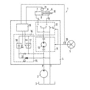
A steering system 1 comprises a pump 2 which
conveys hydraulic fluid from a tank 3 to a steering
control arrangement 4. The steering control
arrangement 4 comprises a pump connection P, which is
- 2Qa~
- 5 -
connected to the pump 2, a tank connection T, which is
connected to the tank 3, and two directional
connections L, R, which are connected to a steering
motor 6, or more accurately speaking, to a left-hand
working chamber 7 and a right-hand working chamber 8 in
the steering motor 6. The two working chambers 7, 8
are separated by a piston 9, to which is fixed a piston
rod 10 which is connected to a wheel (not illustra~ed).
When the piston 9 in the steering motor 6 moves, the
wheel is steered.
The steering control arrangement 4 comprises in
known manner a metering motor section 11 connected to
the pump connection P and a directional section 12
which is connected at one side to the metering motor
section 11 by way of a fluid path and at the other side
to the directional connections R, L, which act as work
connections. Both sections are controlled by the
steering handwheel 5.
The metering motor section 11 has a metering motor
13. In the directional section 12, a directional
valve 14 is opened by the steering handwheel 5. Fluid
is then able to flow from the pump 2 by way of the
meterinq motor 13 and the corresponding directional
connection L, R into the corresponding working chamber
7, 8 of the steering motor 6. The metering motor 13
ascertains the amount of fluid that has flowed through
and closes the directional valve 14 again when an
amount of hydraulic fluid corresponding to the angle of
rotation of the steering handwheel 5 has reached the
steering motor 6. There is a respective connection
between the pump 2 and the steering motor 6, and the
steering motor 6 and the tank 3, only until the
steering motor 6 has assumed a position which
corresponds to the position of the steering handwheel
5. Once this corresponding state has been reached,
that is to say, when an adequate amount of hydraulic
2~5~
fluid has flowed into the steering motor 6, the
directional valve 14 interrupts these connections.
Parallel with the metering motor section 11 there
is arranged a valve arrangement 15 which bridges the
metering motor section 11. The valve arrangement 15
branches off from the fluid path between the metering
motor section 11 and the directional section 12 and is
arranged in an auxiliary fluid path 16 which is
connected to the pump connection P and the tank
connection T respectively. The connection is effected
by way of a plus valve 17, ~ which the hydraulic
fluid can be conveyed from the pump 2 to the
directional connection 12, and a minus valve 18, ~
which the fluid is returned from the fluid path between
the metering motor section 11 and the directional
section 12 to the tank connection T, that is to say,
can be removed from the fluid path.
The plus valve 17 and the minus valve 18 are
constructed as pulse-width modulation controlled
electromagnetic valves. These electromagnetic valves
have an open position and a closed position. On the
appearance of a pulse, they go into the open position.
At the end of the pulse they return to the closed
position and block completely the passage for the
fluid. The opening degree of such valves is adjusted
by way of the duty factor, that is to say the ratio of
the pu~se length to the cycle length.
The plus valve 17 and the minus valve 18 are
controlled by a processing device 19. This processing
device is connected to a sensor 20 for sensing the
angle of the steering handwheel and a sensor 21 for
sensing the angle of the steering motor. The
processing device 19 ascertains the steering angle
error, that is, the difference between the steering
handwheel angle and the steering motor angle, and
compensates for this error by correspondingly opening
~ Q r
the plus valve 17 or the minus valve 18. The
compensation can be effected in such a manner that the
auxiliary fluid flow generated by the plus valve 17 or
the minus valve 18 is dependent on the steering
handwheel speed and/or the steering angle error.
If, for example the position of the s~eering
handwheel 5 is lagging behind the position of the
steering motor 6, the processing device 19 opens the
minus valve 18, that is to say, the steering handwheel
can be rotated without a corresponding movement of the
steering motor 6 being effected. If, in another case,
the position of the steering handwheel 5 is in advance
of the position of the steering motor 6, the processing
device 19 opens the plus valve so that an additional
auxiliary fluid flow is conveyed to the steering motor
6. The steering motor 6 therefore continues to move
as though it were actually corresponding to the
position of the steering handwheel 5.
Between the pump connection P and tank connection
T there is arranged an ~cesc pressure valve 22. This
prevents too great a pressure acting on the plus valve
17 or the minus valve 18. High pressure cannot be
generated by the steering motor 6 either, because,
should the steering motor 6 not be actuated, there is
no connection between the auxiliary fluid path 16, and
thus between the plus valve 17 and the minus valve 18,
and the steering motor 6. The excess pressure valve
22 furthermore prevents the pump pressure acting
directly on the minus valve 18. If this were to be
the case, no fluid would be able to be conveyed by way
of the minus valve to the tank 3. A throttle 23
prevents too much fluid being pumped by the pump 2
directly into the tank 3.