Note: Descriptions are shown in the official language in which they were submitted.
-1- Lowe'
The present invention relates to plant pots with fertilizer holding spaces.
Double-walled plant pots are well lcnown in the horticulture field. A very
5 common type of pot, though not truly double-walled? is one with a perforated bottom and an
integral dish or bowl beneath to hold water. Many double-walled plant pots use the space
between the walls to hold water; some involve fertilizer as well. These and others are
discussed below.
Edging in U.S. patent 4,344,251 issued Aug. 17, 1982, discloses a pot having
a removable inside plate spaced above the bottom of the pot. The soil and plant rest on top
of the plate. The space below the plate is full of water, which wicks upward to the soil and
plant through a porous ceramic rod or tube. The plate is itself impervious to water. Thin
tubes are provided to allow filling the water space from outside. The plate is designed for
15 use with a standard pot having a conical inner surface. The plate is held above the pot
bottom by wedging against the walls. Flings invention is not truly a double-walled pot.
Lancaster, in U.S. patent 4,040,207 issued Aug. 9, 1977, shows a true
double-walled pot; an inner pot nesting within an outer pot. Both pots are of impermeable
20 material. They are arranged to leave a space between them. Special time-release fertilizer
(such as Prowesses brand, made by EM Company) is glued to the outside wall of the inner pot.
Water is poured into the annular gap between the two pots' lips at the top, and runs down
into the space defined by the bottoms of the inner and outer pots. The inner pot has large
holes through the bottom to allow the water to enter the soil in the inner put Lancaster does
25 not teach packing of the space between the walls with loose fertilizer, only adhesively coating
the walls with fertilizer pellets.
Silver, in U.S. patent 4,096,663 issued Jun. 27, 1978, discusses a clay pot
coated on the lower part of the inside surface with an impervious layer. This pot is sex into
30 standing water inside a container. Water travels through the clay and is distributed to soil
,
I
-2-
inside the pot from areas of the clay pot above the impervious coating. Improved moisture
distribution is claimed for the device.
Dryer, in U.S. patent 4,160,342 issued Jul. 10, 1979, discloses nesting pots,
5 both of impervious material. The timer pot closely fits the outer pot along the upper two
thirds, leaving no space between; below this the inner pot is much reduced in diameter to
form a neck, which rests on the bottom of the outer pot. The space defined between the pots
in the lower third within the outer pot, surrounding the neck of the inner putts filled with
water. The neck is filled with a winking material. All the lower surfaces of the inner pot,
10 including those of both the neck and the man portion, are holed for water passage. Thus
water rises through the winking material into the soil above, and excess water drains out. A
side spout is provided for filling the water space.
U.S. design patent 250,401 issued Nov. 28, 1978 to O'Shea et at. shows a
15 similar double pot.
The pot of de Oliveira, disclosed in U.S. patent 4,356,665 issued Nov. 2,
1982, is much Mike that of Dryer, but has three separate necks instead of one in the
lowermost third. Each neck has a small hole in the bottom to admit water to the soil in the
20 inner pot. Water is admitted to the lower chamber, formed between the inner and outer
pots, through a side spout also formed between the outer pot en d the inner pot.
Bilstein, in U.S. patent 4,791,755 issued Dec. 20, 1988, shows a permeable
pot inside an impermeable one. The bottom is wooded with water; a oat rod is used to
25 ascertain the height of the water. The inner pot is filled with a special mixture of
materials, such a plastic pellets, lava, and clay pieces, to control the water environment of
the plant.
-3 -
U.S. patent 4,161,844 issued Jul. 24, 1979 to Hentschel et at. shows a pot
with an annular container on the bottom, containing fertilizer. It is intended for hydroponic
use.
None of the above inventions and patents, talc en either singly or in
combination, is seen to describe foe instant invention as claimed.
The prior art is not seen to disclose any double-walled plant pot which allows
drainage of excess water from the bottom in the usual manner.
Neither is seen a pot having a space or loose organic fertilizer.
Nor is there seen an arrangement for adapting the amount of fertilizer to the
needs of plants of various sizes.
I
It is therefore an object of the present invention to provide a novel plant pot
which overcorrles at least some of the above-mentioned disadvantages of the prior art.
I According to a first aspect of the present invention, there is provided a plant
pox comprising; a water permeable inner container including an inner sleeve having an open
lower end and a bottom plate adapted to close said open lower end, said bottom plate
separable from said inner sleeve, an impermeable outer container body adapted to support
said bottom plate and said inner sleeve, said body composing an outer sleeve adapted to
substantially surround said inner sleeve to define a fertilizer holding space there between, said
outer sleeve having a lower edge, a retaining ledge extending inwardly prom said lower edge,
said retaining ledge having an inner edge, said inner edge defining an open area there within,
said` open area adapted to be covered by said bottom plate, and a lip extending upwardly
from said retainer ledge, said lip adapted with said retaining loge to closely encircle and
support said bottom plate, said lip adapted to hold said inner sleeve in a position relative to
I 2
-4 -
said outer body to define said fertilizer holding space between said inner sleeve and said
outer sleeve, said inner sleeve disposed above said bottom plate when in said position;
whereby when said inner sleeve is held in said pOSitiOII above said bottom plate and said
bottom plate is encircled by said lip, solid bottom plate closes said open lower end of said
S inner sleeve, and said bottom plate and said inner sleeve together define a soil space for
holding soil and a plant or plants there within.
According to a second aspect of the present invention, there is provided a plantpot comprising a water permeable bottom plate, a water permeable side inner wall, and an
10 impermeable side outer wall, said inner wall and said bottom plate defining a soil space
there within, said inner wall and said outer wall defining a fertilizer holding spate
there between.
Thus, the present invention relates to a plant pot with double side walls and a
15 single bottom surrounding a soil space. The inner side wall and the bottom are made
permeable by numerous perforations which are sized to allow water, but not soil or fertilizer,
to pass through. Planting soil is placed in the central part of the pot, and the space between
the double walls is filled with fertilizer mixture.
r~rpically, the bottom of the pot will be a disc and the inner and outer walls
are sections (frustums) of a cone. The outer wall cone is larger in diameter but is inclined
at the same angle as the inner cone.
The fertilizer mixture between the walls contains a variable proportion of
fertilizer to inert ingredients. This proportion is vertically varied: the amount of fertilizer
increases with depth. Thus a young plant with shallow roots, which needs less
fertilizer due to its small size, will not be over-fertilized; when the plant rows large, and
needs more, its roots will reach to the lower regions where more fertilizer is to be found.
Organic fertilizer is preferred.
-5 -
Preferably, the pot is made up of three separable parts: a perforated bottomlessinner sleeve (the inner wall); a perforated bottom plate (the central part of the pot bottom);
and an impermeable outer container with an opening on the lower end. This
opening is slightly smaller than the bottom plate, to Support it. The outer container includes
S the side wall, a ledge (the outer annular part of the bottom surrounding the plate), and a lip
on the ledge adapted to hold the perforated bottom plate and the inner sleeve in their
positions.
The bottom plate fits within the lowermost inner edge of the inner sleeve.
This construction allows a plant to be easily removed by merely pushing upward on the
bottom plate. The soil and the intact root system of the plant will then slide out.
The present invention will now be described, by way of example only, with
reference to the attached figures, wherein:
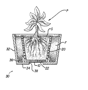
Fig. 1 is a cross section of the present invention showing a plant in soil held
by the bottom plate and side sleeve, and fertilizer held between the inner wall sleeve and the
outer wall or container; and
Fig. 2 is an exploded perspective view showing the container, bottom plate,
and inner sleeve. No soil, fertilizer or plant is shown in Fig. 2.
Similar reference characters denote corresponding features consistently
throughout the attached drawings.
Fig 1 shows the instant invention assembled and holding soil S and fertilizer
mixture F. A plant P is rooted in soil S.
The soil is held in a soil space defined by an inner wall and a bottom. The
inner wall element is a sleeve 20, and the bottom is a plate 10. The plate 10 fits within the
open lower end of the sleeve 20.
-6-
Both the bottom plate 10 and the inner sleeve 20 are permeable to water.
Preferably, permeability is achieved by numerous perforations 2 as shown most clearly in
Fig. 2. These perforations should be sized to allow water, but not soil or fertilizer
mixture particles to pass through.
The plate 10 and inner sleeve 20 will normally be formed of impermeable
materials such as metal or plastic. However, they could also be formed of other, permeable
mottles such as fired clay, rigid open-cell foam, and the like, which require no perorations
.
Partially surrounding and supporting the plate 10 and sleeve 20 is a an outer
container body 30, made of water-impermeable materials. The structure is most clearly
shown in Fig. 2. The body includes an outer wall or sleeve 32 generally parallel to the inner
sleeve 20, a lower retaining ledge 34 having the shape of an ~mmllar disc, and a lip 36 on the
15 upper surface of the ledge. These parts are either formed as one piece, as by mounding? or
are joined permanesltly, as by welding.
The outer sleeve 32, together with the inner sleeve 20 and that portion of the
ledge 34 outside of the lip 36, acts to define a fertilizer holding space. Fertilizer mixture
20 may be held in this space as shown in Fig. 1.
The inner sleeve 20 is located relative to the outer sleeve 32 by the tip 36.
The bottom plate 10 is located horizontally by the inside surface of the open lower end of the
inner sleeve 20, and is located vertically by gravity and the inner edge 38 of the ledge 34.
I
The open area inside the inner edge 38 allows excess water to drain prom the
soil S through the permeable bottom plate 10.
The fertilizer mixture F is preferably composed of organic fertilizer and inert
30 ingredients. The proportion of fertilizer to inert ingredients is variable. In the present
invention this proportion may be varied from place to place within the fertilizer holding
space to help growing plants absorb the proper amount of fertilizer. As plants will generally
be located centrally in the soil S, the symmetry of the plant and pot lead to the conclusion
that variations in fertilizer proportion will be most useful if the variation is a function of
5 vertical height, or, equivalently, distance from the ledge 34.
Preferably, the proportion will be higher in the lower parts of the mixture F,
for the reasons following.
A small young plant in the soil S will have a shallow root system; it also
requires less fertilizer than a larger plant. As the young plant's roots reach out toward the
fertilizer holding space, they will encounter a relatively low concentration of
fertilizer and avoid "burning" of the roots.
Later, when the plant has grown, it will require more nutrients. The roots
will now reach toward the bottom of the pot, and will encounter a higher concentration of
fertilizer there due to the higher proportion of fertilizer in the mixture F.
During a watering cycle, the drainage of water downward from the top surface
of the soil S will carry leached nutrients downward. Thus the amount of nutrient released
during a watering cycle increases with depth. Also, the outer sleeve 34, retaining ledge 34,
and lip 36 together form a reservoir which retains a portion of the natural concentration of
organic fertilizer nutrients.
It will be seen that the three components of the present invention (that is, theplate 10, sleeve 20, and body 30) are each adapted to nesting when stacked. This will allow
the present invention to be stored and shipped in a small volume.
Z~5~S~2
-8-
It is to be understood that the present invention is not limited to the sole
embodiment described above, but encompasses any and all embodiments within the scope of
the following claims.
For example, the pot could be made as one unit, with the bottom 10, sleeve
20, and body 30 integral. Or, the shapes of the pieces could vary from that shown in the
gurus: the bottom plate could be concave, the sides square, etc.
- -