Note: Descriptions are shown in the official language in which they were submitted.
20S48~
ROTARY REGENERATIVE AIR PREHEATER BASKET SEALING
BACKGROUND AND SUMMARY OF THE INVENTION
The present invention relates to rotary regenerative heat
transfer devices and, more particularly, to air preheaters wherein
the individual heat transfer elements are stacked in open baskets
which, in turn, are disposed in compartments in the rotor of the
transfer device.
Air preheaters utilize the heat that would otherwise be
lost out the smoke stacks of industrial and central power station
boilers. In the preheater, this waste heat is captured before it
reaches the stack and is transferred to the incoming cold air.
Thousands of specially formed steel sheets - called heat transfer
elements - absorb the waste heat from hot gases flowing through one
half of the preheater structure - and release it to the incoming cold
air as it passes through the other half of the structure. The heat
transfer elements are spaced and arranged in a cylindrical shell
called the rotor. The spaces between the elements allow the air and
gas streams to flow across the surface of each sheet. The rotor
revolves slowly within the preheater structure, carrying the elements
alternately through the air and gas streams so that there is a
continuous transfer of heat.
As a means of facilitating the efficient removal and
replacement of the heat transfer elements in an air preheater, it is
the common practice to stack the individual elements in baskets which
are inserted into compartments formed in the rotor. To reduce both
weight and cost, the element baskets most commonly comprise an open
frame, rather than solid walls.
~,
C900940 ~ ~
2054~86
_ - 2 -
After the heat transfer device has been in service for
some time, the diaphragms and stay plates which define the basket-
receiving compartments may become distorted by the operating
conditions to which they are exposed. To insure that the baskets may
be freely inserted and removed from the compartments, despite such
distortion, the baskets are generally undersized. Thus, substantial
gaps exist between the baskets and the rotor compartment walls.
These gaps allow a portion of the gas and air flows to bypass the
heat transfer elements, resulting in a loss of thermal efficiency.
It is, therefore, a primary object of the present
invention to provide an element basket for an air preheater or
similar heat transfer device wherein the gas and air flows are
constrained to pass substantially completely over the heat transfer
elements.
It is a further object to provide such an element basket
which may be readily inserted and removed from a basket-receiving
compartment in the rotor.
It is yet another object to provide an element basket as
aforesaid which is light in weight and inexpensive to produce.
The foregoing and other objects as may hereinafter appear
are achieved by an element basket including at least one side sealing
member consisting of an imperforate sheet fastened on the outside of
the basket frame and substantially completely covering a side of the
basket, a distal edge portion of the sheet being bent back upon
itself and biasable against a wall surface of the rotor. The side
sealing member fills the gaps between the element basket and the
adjacent rotor compartment wall, preventing gas or cold air from
bypassing the heat transfer elements in the basket.
BRIEF DESCRIPTION OF THE DRAWINGS
Figure 1 is a perspective view of a conventional element
basket for an air preheater;
Figure 2 is a fragmentary top plan view of an air
preheater rotor;
Figure 3 is a side view of a side sealing member in
accord with the present invention; and
C900940
2054~G
_ - 3 -
Figure 4 is a fragmentary cross-sectional view of an
element basket, arranged in accord with the present invention,
installed in a rotor.
DESCRIPTION OF THE PREFERRED EMBODIMENT
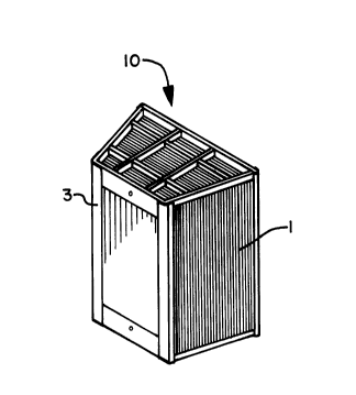
A conventional element basket 10 comprises a plurality of
heat transfer elements 1 stackingly retained in an open frame 3 so as
to provide passage for gas or cold air therebetween.
There is shown, in Figure 2, a segment of an air
preheater rotor 5. Rotor 5, which in its entirety is cylindrical, is
divided by diaphragms 7 and stay plates 9 into a number of
compartments 11 each adapted to receive an element basket 10.
Element baskets 10 are appreciably smaller than compartments 11 in
which they are received, to allow for ready insertion and removal
despite distortion of compartment-defining diaphragms 7 and stay
plates 9. As a result of this size disparity, there are substantial
gaps 13 between baskets 10 and the compartment walls, through which
gas or cold air may flow.
To prevent flow through gaps 13, element baskets 10 are
provided with at least one side sealing member 15 which consists of
an imperforate sheet 17 of thin steel, from 16 to 24 gauge thickness,
tack welded to the outside of frame 3, completely covering one side
thereof. A distal edge portion 19 of sheet 17 is bent back upon
itself so as to be biasable against a wall surface of rotor
compartments 11. Edge portion 19 forms an included angle of between
about 45 and about 70, with the body of sheet 17, terminating
approximately 1-1/2 inches to 2 inches therefrom. A right-angled
flange 21 is provided, opposite distal edge portion 19, to facilitate
attachment of side sealing member 15 to frame 3.
As best seen in Figure 4, distal edge portion 19 fills
gap 13 between element basket 10 and the adjacent compartment-
defining diaphragm 7 or stay plate 9. A side sealing member 15 may
be installed on each side of element basket 10 where gap 13 exceeds a
predetermined limit. Installation is accomplished by roughly forming
edge portion 19 in a pre-cut piece of sheet steel. The roughly
formed sheet 17 is then driven between basket 11 and the adjacent
compartment wall with a metal bar having an appropriately radiussed
C900940
20~4886
_ - 4 -
nose portion. With sheet 17 in proper position, flange 21 is formed
by bending sheet 17 against frame 3, and then tack welded in place.
C900940