Language selection

Search

Patent 2054992 Summary

Third-party information liability

Some of the information on this Web page has been provided by external sources. The Government of Canada is not responsible for the accuracy, reliability or currency of the information supplied by external sources. Users wishing to rely upon this information should consult directly with the source of the information. Content provided by external sources is not subject to official languages, privacy and accessibility requirements.

Claims and Abstract availability

Any discrepancies in the text and image of the Claims and Abstract are due to differing posting times. Text of the Claims and Abstract are posted:

  • At the time the application is open to public inspection;
  • At the time of issue of the patent (grant).
(12) Patent: (11) CA 2054992
(54) English Title: POSTURE BOARD
(54) French Title: PLANCHE POSTURALE
Status: Expired
Bibliographic Data
(51) International Patent Classification (IPC):
  • A61F 5/01 (2006.01)
  • A47C 20/02 (2006.01)
  • A61G 7/07 (2006.01)
(72) Inventors :
  • SHIELDS, MARY (Canada)
(73) Owners :
  • SHIELDS, MARY (Canada)
(71) Applicants :
  • SHIELDS, MARY (Canada)
(74) Agent: DENNISON ASSOCIATES
(74) Associate agent:
(45) Issued: 1997-01-14
(22) Filed Date: 1991-11-05
(41) Open to Public Inspection: 1993-05-06
Examination requested: 1993-06-08
Availability of licence: N/A
(25) Language of filing: English

Patent Cooperation Treaty (PCT): No

(30) Application Priority Data: None

Abstracts

English Abstract


The posture board according to the present
invention is contoured to a spinal mating shape. The board
comprises an upper back supporting portion having a leading
edge and a lower back supporting portion terminating in a
trailing edge. The board has a longitudinally extending
sine wave configuration with an up curve at the lower back
supporting portion. The board further has a side to side
concave curvature defining a trough like center region and
upwardly turned outside edges. The center region along at
least part of the upper back supporting portion and at the
trailing edge is in contact with the supporting surface on
which the posture board is used. The up curve defines a gap
beneath the center region along the lower back supporting
portion and the supporting surface. The outside edges of
the board are more flexible than the center region to allow
some edge flattening while the center region is much less
flexible to prevent lengthwise full flattening of the board
at the center region under weight of a user such that the
board provides vibratory feedback responsive to body
vibrations given off by the user.


Claims

Note: Claims are shown in the official language in which they were submitted.

- 6 -

THE EMBODIMENTS OF THE INVENTION IN WHICH AN EXCLUSIVE
PROPERTY OR PRIVILEGE IS CLAIMED ARE DEFINED AS FOLLOWS:

1. A posture board contoured to a spinal mating shape
comprising an upper back supporting portion having a leading
edge and a lower back supporting portion terminating in a
trailing edge, said board having a longitudinally extending
sine wave configuration with an up curve at said lower back
supporting portion and a side to side concave curvature
defining a center region with upwardly turned outside edges,
said center region, along at least part of said upper back
supporting portion and at said trailing edge being in
contact with a supporting surface on which said posture
board is used, said up curve defining a gap between said
center region along said lower back supporting portion and
such supporting surface, said outside edges being relatively
flexible to allow downward bending of said edges, said
center region being less flexible than said edges and
preventing lengthwise flattening of said board under weight
of a user such that said board provides vibratory feedback
responsive to body vibrations given off by the user.

2. A posture board as claimed in Claim 1 comprising a
one piece wooden core layer and a padded layer over said
wooden core layer.

3. A posture board as claimed in Claim 1, having a
lesser side to side concave curvature at said leading edge
than at said trailing edge of said board.

4. A posture board as claimed in Claim 3, wherein said
outside edges at said leading edge are more flexible than
said outside edges at said trailing edge.

Description

Note: Descriptions are shown in the official language in which they were submitted.


zo~99~
SJ-8336-91 - 1 - 5082B/0~05B


FIELD OF THE IN~ENTION

The present invention relates to a posture board or
back support.


BACKGROUND OF THE IN~ENTION

Many people suffer from back problems. One of the
primary causes for back problems is incorrect posture when
10 sitting, standing and lying down.

There are a presently available a relatively
limited number of effective back supporting aids. Those
that are available are usually nothing more than thick pads
15 for cushioning the back. These types of thick pads do not
provide adequate posture training nor are they sensitive to
natural vibrations given off by the body.

SUMMARY OF THE PRESENT INVENTION
The present invention provides a posture board or
back support usable in either a sitting or a lying mode and
specifically designed to not only mate with the contour of
the back or spinal region but to also cooperate with natural
25 body rhythms particularly inducive to training the spinal
region to assume a position of correct posture. In
particular the posture board of the present invention is
contoured to a spinal mating shape and comprises an upper
back supporting portion having a leading edge and a lower
30 back supporting portion terminating in a trailing eàge. The
board has a longitudinally extending sine wave configuration
with an up curve at the lower back supporting portion. The
board also has a side to side concave curvature defining a
trough like center region with upwardly turned outside
35edges. The center region along at least part of the upper

Z(35~99Z
SJ-8336-91 - 2 - 5082~/0105

back supporting portion and at the trailing edge of the
board is in contact with the supporting surface on which the
posture board is used. The up curve defines a gap between
the center region along the lower back supporting portion
and the supporting surface. The board is more flexible and
bends downwardly at its outside edges while being less
flexible at the center region to prevent full lengthwise
flattening of the board under weight of a user thereby
providing vibratory feedback responsive to body vibrations
given off by the user.

BRIEF [)ESCRIPTION OF THE I~RAWINGS

The above as well as other advantages and features
of the present invention will be described in greater detail
according to the preferred embodiments of the present
invention in which;
Figure 1 shows a person in a supine position using
a posture board in accordance with a preferred embodiment of
the present invention;
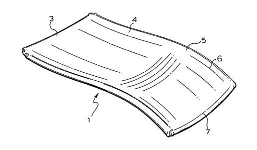
Figure 2 is a perspective view of the posture board
used by the person of Figure l;
Figure 3 is a further perspective view showing in
cut away the posture board of Figure 2;
Figure 4 is a top plan view of the posture board of
Figure 2;
Figure 5 is a sectional view along the lines 5-5 of
Figure 4;
Figure 6 is a sectional view along the lines 6-6 of
Figure 4;
Figure 7 is an end view showing the leading edge of
the posture board of Figure 2;
Figure 8 shows downward flexing of the leading edge
shown in Figure 7;
Figure 9 is an end view of the trailing edge of the

2054~92
SJ-8336-91 - 3 - 5082B/0105B

posture board of Figure 2;
Figure lO shows downward flexing of the trailing
edge shown in Figure 9.

DETAILED DESCRIPTION ACCORDING TO THE PREFERRED
EMBODIMENTS-OF THE PRESENT IN~ENTION IN WHICH:
Figure l shows an individual lying down on a
posture board or back support generally indicated at l. the
lO posture board has sine wave like configuration beginning
with a leading edge 3 of upper back supporting portion 4
extending down to a high point or pinnacle region 5
continuing to a lower back supporting portion 6 which
terminates in a trailing edge 7. The pinnacle region is
15 about two-thirds along the length of the posture board so
that the upper back supporting portion 4 is of increased
length relative to the lower back supporting portion 6. In
the preferred embodiment, the posture board has an overall
length of about one and a half feet with the pinnacle region
205 being located about a foot from the leading edge of the
board.

In the embodiment shown, the board has a layered
construction. This layered construction is based on an
25interior core layer 9 which is made of wood. The wood is
covered with a padded foam layer 11 covered outwardly by a
protective cover or skin 13. The foam layer is preferabiy
no more than about one quarter of an inch in thickness and
cover 13 is preferably made from a vinyl or vinyl-like
3~aterial which is easily cleanable and which is relatively
low in cost for manufacturing of the board.

In another embodiment the posture board is
constructed from a single piece of plastic or other similar
3~aterial having the same spinal mating configuration as

20~992
SJ-8336-91 - 4 - 5082B/OiO5B

described aboye. With this shape and as a result of the
board's flex characteristics, to be described later in
detail, the board is able to pick up the vibrational
characteristics naturally given off by body rhythms of the
user. These body rhythms are classified as primary rhythms
resulting from the flow of spinal fluid through the body and
respiratory rhythms which occur as the result of breathing.
The shape and flex of the board provide it with vibrational
characteristics such that it is able to tune itself with the
10 body rhythms and provide a vibratory feedback which matches
that of the body.

Figures 7 and 9 show that the board has a side to
side concave curvature with upwardly curved outside edges 15
15 and a depressed or trough like center region 13. Without
the weight of the user on the board, it is in contact with a
supporting surface S at both its leading and its trai~ing
edges along the center region. As best seen in Figure 6 of
the drawings, the center region also contacts the supporting
20 surface part way along the upper back supporting portion and
is gapped from the supporting surface at the pinnacie of the
lower back supporting portion.

The board has a flex pattern which varies from one
25part of the board to another. In particular, as can be seen
in Figure 8 of the drawings, the board is relatively flexible
at its outside edges particularly at its leading edge 3 such
that the board will essentially flatten under the weight of a
user from side to side at the leading edge. The outside edge
300f the board at the trailing edge as represented in Figures
9 and 10 have a greater up curvature than at the leading edge
and are slightly stiffer so that although they do flex bown-
wardly, they do not flatten to the extent of that found at
the leading edge of the board under the weight of the user.


20S~992
~_ SJ-8336-91 - 5 - 5082B/OiO5B

The center region of the board is relatively stiff
or inflexible compared to the outside edges and is
sufficiently strong that it will not allow lengthwise
flattening of the board under weight of a user, even a
person of very substantial size, thereby maintaining the gap
between it and the supporting surface at the lower back
supporting portion of the board. As a result, much of the
board remains elevated from ground level. However, the
center region at the gap is not without some flex and is
10 therefore able to respond to the body rhythms given off by
the user as earlier described, i.e. because the board does
not completely flatten lengthwise onto the supporting
surface, it is able to move up and down with the body
rhythms.
The side to side curvature of the board provides a
proper fit and feel for the user to center himself or
herself on the board. As the board flattens from siae to
side under weight, particularly at its leading edge near the
20shoulders of the user as best seen in Figure 1, it provides
a much wider support or base beneath the user which
substantially eliminates any side to side rocking of the
board while in use.

Although various preferred embodiments of the
invention have been described in detail, it will be
appreciated by those skilled in the art that variations may
be made without departing from the spirit of the invention
or the scope of the appended claims.


Representative Drawing
A single figure which represents the drawing illustrating the invention.
Administrative Status

For a clearer understanding of the status of the application/patent presented on this page, the site Disclaimer , as well as the definitions for Patent , Administrative Status , Maintenance Fee  and Payment History  should be consulted.

Administrative Status

Title Date
Forecasted Issue Date 1997-01-14
(22) Filed 1991-11-05
(41) Open to Public Inspection 1993-05-06
Examination Requested 1993-06-08
(45) Issued 1997-01-14
Expired 2011-11-05

Abandonment History

There is no abandonment history.

Payment History

Fee Type Anniversary Year Due Date Amount Paid Paid Date
Application Fee $0.00 1991-11-05
Maintenance Fee - Application - New Act 2 1993-11-05 $50.00 1993-11-05
Maintenance Fee - Application - New Act 3 1994-11-07 $50.00 1994-10-26
Maintenance Fee - Application - New Act 4 1995-11-06 $50.00 1995-11-02
Maintenance Fee - Application - New Act 5 1996-11-05 $75.00 1996-11-05
Maintenance Fee - Patent - New Act 6 1997-11-05 $75.00 1997-11-05
Maintenance Fee - Patent - New Act 7 1998-11-05 $75.00 1998-10-30
Maintenance Fee - Patent - New Act 8 1999-11-05 $75.00 1999-10-11
Maintenance Fee - Patent - New Act 9 2000-11-06 $75.00 2000-11-03
Maintenance Fee - Patent - New Act 10 2001-11-05 $100.00 2001-11-05
Maintenance Fee - Patent - New Act 11 2002-11-05 $100.00 2002-10-02
Maintenance Fee - Patent - New Act 12 2003-11-05 $100.00 2003-11-04
Maintenance Fee - Patent - New Act 13 2004-11-05 $125.00 2004-10-29
Maintenance Fee - Patent - New Act 14 2005-11-07 $125.00 2005-11-01
Maintenance Fee - Patent - New Act 15 2006-11-06 $225.00 2006-11-01
Maintenance Fee - Patent - New Act 16 2007-11-05 $225.00 2007-10-30
Maintenance Fee - Patent - New Act 17 2008-11-05 $225.00 2008-10-29
Maintenance Fee - Patent - New Act 18 2009-11-05 $225.00 2009-10-30
Maintenance Fee - Patent - New Act 19 2010-11-05 $225.00 2010-11-04
Owners on Record

Note: Records showing the ownership history in alphabetical order.

Current Owners on Record
SHIELDS, MARY
Past Owners on Record
None
Past Owners that do not appear in the "Owners on Record" listing will appear in other documentation within the application.
Documents

To view selected files, please enter reCAPTCHA code :


To view images, click a link in the Document Description column. To download the documents, select one or more checkboxes in the first column and then click the "Download Selected in PDF format (Zip Archive)" or the "Download Selected as Single PDF" button.

List of published and non-published patent-specific documents on the CPD .

If you have any difficulty accessing content, you can call the Client Service Centre at 1-866-997-1936 or send them an e-mail at CIPO Client Service Centre.


Document
Description 
Date
(yyyy-mm-dd) 
Number of pages   Size of Image (KB) 
Abstract 1997-01-14 1 29
Cover Page 1997-01-14 1 12
Description 1997-01-14 5 194
Claims 1997-01-14 1 43
Drawings 1997-01-14 3 66
Representative Drawing 1998-09-28 1 11
Cover Page 1993-12-14 1 15
Abstract 1993-12-14 1 29
Claims 1993-12-14 1 41
Drawings 1993-12-14 3 72
Description 1993-12-14 5 191
Correspondence 1991-11-05 1 49
PCT Correspondence 1996-11-01 1 38
Prosecution Correspondence 1993-06-08 1 36
Correspondence 2008-10-29 1 15
Fees 1996-11-05 1 43
Fees 1995-11-02 1 38
Fees 1994-10-26 1 39
Fees 1993-11-05 1 31