Language selection

Search

Patent 2055139 Summary

Third-party information liability

Some of the information on this Web page has been provided by external sources. The Government of Canada is not responsible for the accuracy, reliability or currency of the information supplied by external sources. Users wishing to rely upon this information should consult directly with the source of the information. Content provided by external sources is not subject to official languages, privacy and accessibility requirements.

Claims and Abstract availability

Any discrepancies in the text and image of the Claims and Abstract are due to differing posting times. Text of the Claims and Abstract are posted:

  • At the time the application is open to public inspection;
  • At the time of issue of the patent (grant).
(12) Patent: (11) CA 2055139
(54) English Title: THERMAL TONER FIXING DEVICE AND METHOD FOR XEROGRAPHIC APPARATUS
(54) French Title: DISPOSITIF ET METHODE DE FIXATION THERMIQUE DE TONER POUR APPAREIL XEROGRAPHIQUE
Status: Expired
Bibliographic Data
(51) International Patent Classification (IPC):
  • G03G 15/20 (2006.01)
  • G03G 13/16 (2006.01)
  • G03G 13/20 (2006.01)
  • G03G 15/16 (2006.01)
(72) Inventors :
  • MATSUDA, YASUHIKO (Japan)
(73) Owners :
  • KABUSHIKI KAISHA SATO (Japan)
(71) Applicants :
(74) Agent: MCCARTHY TETRAULT LLP
(74) Associate agent:
(45) Issued: 1999-05-04
(22) Filed Date: 1991-11-07
(41) Open to Public Inspection: 1992-05-08
Examination requested: 1993-11-17
Availability of licence: N/A
(25) Language of filing: English

Patent Cooperation Treaty (PCT): No

(30) Application Priority Data:
Application No. Country/Territory Date
2-302269 Japan 1990-11-07

Abstracts

English Abstract


A thermal toner fixing device for a xerographic
apparatus comprises a heat dissipation mechanism for
dissipating heat accumulating in a pressure roller
rotating in contact with a heat roller so as to achieve
substantially uniform thermal deformation throughout the
pressure roller and, as a result, uniform contact with
the heat roller irrespective of the width of the paper
sheet being conveyed. The device enables both wide and
narrow sheets of paper to be properly conveyed with high
reliability. Preferably, the heat dissipation mechanism
is a heat dissipation roller in contact with the pressure
roller, and the heat dissipation roller has a
substantially hollow interior for the passage of
circulating cooling air.


French Abstract

Dispositif de fixage thermique de toner pour appareil xérographique. Comprend un mécanisme de dissipation de chaleur pour dissiper la chaleur qui s'accumule dans un rouleau de pression tournant en contact avec un roulant chauffant de façon à produire une déformation thermique essentiellement uniforme à travers le rouleau de pression, en assurant ainsi un contact uniforme avec le rouleau chauffant quelle que soit la largeur de la feuille de papier transportée. Le dispositif permet le transport de feuilles larges et de feuilles étroites avec une grande fiabilité. De préférence, le mécanisme de dissipation de chaleur est un rouleau de dissipation de chaleur en contact avec le rouleau de pression, le rouleau de dissipation de chaleur, essentiellement creux, laissant passer un courant d'air de refroidissement.

Claims

Note: Claims are shown in the official language in which they were submitted.


WHAT IS CLAIMED IS:

1. In a thermal toner fixing device for a xerographic
apparatus which fixes a toner image to a sheet of paper having
the toner image disposed thereon by heating the sheet of paper
as it is passed between a rotatable heat roller and a
rotatable pressure roller in contact with the heat roller,
heat dissipation means for dissipating heat accumulating in
the pressure roller and for maintaining heat deformation of
the pressure roller substantially uniform, the heat
dissipation means comprising a heat absorbing roller in
contact with the pressure roller for dissipating heat absorbed
by the pressure roller from the heat roller, the heat
absorbing roller including a substantially hollow interior, a
central hub, a cylindrical roller surface disposed radially
outward from said hub, an inner surface facing said hub, and a
plurality of substantially equiangularly spaced heat
dissipation fins disposed in the hollow interior and extending
radially between the hub and the inner surface for connecting
said hub to said cylindrical surface and for dissipating heat
absorbed by the cylindrical surface into the hollow interior,
and further comprising a cooling fan for circulating air and
removing heat from said hollow interior.

2. A thermal toner fixing device for a xerographic
apparatus which fixes a toner image previously deposited on a
sheet of paper to the sheet of paper by heating the sheet of
paper as it is passed through the toner fixing device, the
device comprising a rotatable heating roller and a rotatable
pressure roller in contact with the heating roller, and
further comprising heat dissipation means for absorbing heat
from said pressure roller and for maintaining heating of the


-2-
pressure roller substantially uniform across the surface of
the pressure roller, the heat dissipation means comprising a
heat absorbing roller in contact with the pressure roller for
dissipating heat absorbed by the pressure roller from the
heating roller, the heat absorbing roller including a
substantially hollow interior, a central hub, a cylindrical
roller surface disposed radially outward from said hub, an
inner surface facing said hub, and a plurality of
substantially equiangularly spaced heat dissipation fins
disposed in the hollow interior and extending radially between
the hub and the inner surface for connecting said hub to said
cylindrical surface and for dissipating heat absorbed by the
cylindrical surface into the hollow interior, and further
comprising a cooling fan for circulating air and for removing
heat from said hollow interior.

3. A method for cooling a pressure roller in a thermal
toner fixing device of a xerographic apparatus wherein a sheet
of paper having a toner image previously deposited thereon is
fixed to the sheet of paper as the sheet of paper passes
between a heating roller and the pressure roller, the method
comprising a step of dissipating heat absorbed by said
pressure roller from said heating roller so as to remove
excess heat accumulating in areas of said pressure roller and
maintain heating of said pressure roller substantially
uniform, said step of dissipating heat comprising a step of
providing a heat dissipating roller having a substantially
hollow interior and a plurality of substantially equiangularly
spaced heat dissipation fins extending radially between a hub
of said heat dissipating roller and an inner surface of said
heat dissipating roller and said heat dissipating roller being


-3-
in contact with said pressure roller for absorbing heat from
said pressure roller, said step of providing a heat
dissipating roller in contact with said pressure roller
further comprising a step of circulating cooling air through
the substantially hollow interior of said heat dissipating
roller.

4. Apparatus for preventing jamming and for allowing
proper conveyance of a sheet of paper between a heating roller
and a pressure roller in a thermal toner fixing station of a
xerographic apparatus, the sheet of paper having a toner image
to be fixed deposited thereon, the apparatus comprising heat
absorption means in contact with the pressure roller for
absorbing heat accumulating in the pressure roller and for
maintaining heating of the pressure roller substantially
uniform across the surface of the pressure roller and for
preventing non-uniform heating of the pressure roller, the
heat absorption means comprising a heat dissipating roller
having an outer surface in contact with the pressure roller,
an interior of the heat dissipating roller being substantially
hollow for passage of cooling air, the heat dissipating roller
having a plurality of substantially equiangularly spaced heat
dissipating fins in the substantially hollow interior, the
fins extending radially between a central hub of said heat
dissipating roller and an inner cylindrical surface of said
heat dissipating roller adjacent the outer surface of the heat
dissipating roller.

Description

Note: Descriptions are shown in the official language in which they were submitted.


2055~9


THERMAL TONER FIXING DEVIcE AND
METHOD FOR XEROGRAPHIC APPARATUS

The present invention relates to a thermal
toner fixing device for a xerographic apparatus.
In most xerographic apparatus, the surface of
an electrostatically charged photosensitive drum is
exposed to image carrying light to form a latent image
thereon, toner is adhered to the latent image to develop
it, and the toner image is transferred to a sheet of
paper and fixed thereon.
The toner fixing operation in this process is
commonly conducted using a thermal toner fixing device
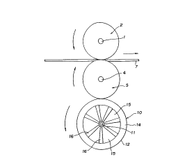
like the one shown in Figure 3. This device has a heat
roller 2 rotatably supported on a shaft 1 and heated by
an appropriate heat source to a temperature of around
180~C, and a silicon rubber pressure roller 5 supported
on a shaft 4. The surface 3 of the heat roller 2 and the
surface 6 of the pressure roller 5 are forced against
each other at a prescribed pressure. When a sheet of
paper 7 bearing a toner image is inserted between the
rollers 2 and 5 and the rollers are inAep~n~ently rotated
for passing the sheet therebetween, the toner is melted
and fixed to the paper by the heat of the heat roller 2.
When a sheet of paper 7 that is narrower than
the width (lateral length) of the heat roller 2 is passed
between the rollers, the pressure roller 5 absorbs more
heat at the portions where the paper is not present than

,r4745

20551~9


at the portions where it is. The temperature at the
surface of the pressure roller 5 therefore rises to
around 180~C at portions where it is in direct contact
with the heat roller 2, as compared with only around 50~C
at portions where it indirectly contacts the heat roller
2 through the paper.
The diameter of the pressure roller 5 at the
portions on opposite sides of the paper 7 therefore
increases considerably owing to thermal expansion. As a
result, the heat roller 2 is pushed upward, with the non-
uniform heating producing an inclined step 8 (exaggerated
in the figure for clarity) in the pressure roller 5 on
either side of the portion in contact with the paper 7
and a gap 9 between the surface 3 of the heat roller 2
and the surface 6 of the pressure roller 5 at the portion
where the paper is present. This is apt to give rise to
slippage between the paper 7 and the rotating heat and
pressure rollers so that the paper 7 is liable to be
improperly conveyed and may jam.

It is an object of the present invention to
provide a thermal toner fixing device for a xerographic
apparatus in which heat accumulating in the pressure
roller is dissipated so as to achieve uniform thermal
deformation throughout the pressure roller and thus
enable both wide and narrow sheets of paper to be
conveyed accurately and quickly.
For realizing this object, the mech~ism
according to this invention provides a thermal toner
fixing device for a xerographic apparatus equipped with a
#4745

2055~39


heat dissipation mechanism for dis~ipating heat
accumulating in the pressure roller.
In the thermal toner fixing device for a
xerographic apparatus according to the invention, since
heat accumulating in the pressure roller is dissipated by
the heat dissipation e-h~nism~ non-uniform heat
deformation of the pressure roller is prevented and the
surface temperature of the pres~ure roller ~ec -~
relatively even throughout.
Since the whole surface of the pressure roller
is therefore pressed onto the surface of the heat roller
at the prescribed pressure, sheets of paper can be
conveyed accurately and quickly by the rotation of the
heat and pressure rollers without slipping or jamming.
Other features and advantages of the present
invention will bec: e apparent from the following
description of the invention which refers to the
acc.-,-nying drawings.

Figure 1 is a schematic front view of a thermal
toner fixing device according to the invention.
Figure 2 is a schematic side view of the
thermal toner fixing device of Figure 1.
Figure 3 is a schematic front view of a
conventional thermal toner fixing device.

The invention will now be explained with
reference to an embodiment thereof shown in Figures 1 and
2. The constituent elements of this embodiment
~745

20~139


corresponding to those of the conventional device
described above are assigned the same reference numerals
as in the earlier description and will not be explained
here again.
In the figures, reference numeral 10 designates
a hollow aluminum heat dissipation drum rotatably
supported on a shaft 11 at an appropriate location in a
xerographic apparatus (not shown).
The upper part of the surface 12 of the heat
dissipation drum 10 is pressed onto the surface 6 of the
pressure roller 5 at a prescribed pressure, whereby it
absorbs heat by conduction from the pressure roller 5 and
rotates in the direction indicated by an arrow in Figure
2 when the pressure roller 5 rotates in the direction
indicated by another arrow. The heat dissipation drum 10
is open at both lateral ends 13 and 14. A plurality of
equiangularly spaced heat dissipation fins 16 extend
radially between the shaft 11 at the center of the hollow
interior 15 of the heat dissipation drum 10 and the inner
surface of the drum 10.
The heat absorbed by the heat dissipation drum
10 from the pressure roller 5 is thus dissipated both
through the portions of its surface 12 not in contact
with the pressure roller and through the heat dissipation
fins 16 into the hollow interior 15.
A duct 17 provided in c~: n;cation with the
end 13 of the heat dissipation drum 10 is provided
internally with a rotating fan 18 powered by a motor not
shown in the figures.
An air stream generated by the rotation of the
fan 18 passes from the end 13, through the hollow drum
,y4745

CA 020~139 1998-12-04
_ _


interior 15 and out the other end 14, carrying with it
the air within the hollow interior lS that has been
warmed by the heat dissipated by the fins 16.
The operation of the thermal toner fixing
device made in the foregoing manner will now be
explained.
When a narrow piece of paper 7 of a width
smaller than that of the pressure roller 5 is passed
between the pressure roller 5 and the heat roller 2, high
temperature heat is directly conducted from the heat
roller 2 to the portions of the pressure roller 5 on the
opposite sides of the paper 7, while high temperature
heat is also conducted from the heat roller 2 to the
center region of the pressure roller 5 through the paper
7.
This heat is thereafter conducted from the
pressure roller 5 to the heat dissipation drum 10
rotating in contact therewith and is dissipated both from
the surface 12 of the heat dissipation drum 10 and from
the heat dissipation fins 16 into the hollow interior 15.
' The air in the hollow interior lS warmed by the
heat from the fins 16 is then blown by the fan 18 from
the end 13 of the heat dissipation drum 10, through the
hollow interior lS and to the outside through the other
end 14. The hollow interior lS of the heat dissipation
drum 10 is therefore cooled, thereby promoting the
dissipation of heat from the fins 16 and, in turn, the
absorption of heat by the heat dissipation drum 10 from
the pressure roller S. As a result, the opposite end
regions of the pressure roller S are prevented from

20~139


rising to a high temperature and, therefore, from
experiencing undue thermal expansion.
In addition, the movement of the hot air in the
hollow interior 15 of the heat dissipation drum 10 by the
fan 18 warms the central region of the heat dissipation
drum 10, which is at a lower temperature than the regions
toward the ends 13 and 14, and this in turn warms the
central portion of the pressure roller 5 in contact with
tha central portion of the heat dissipation drum 10 and
causes it to undergo thermal expansion.
As a consequence, the heat distribution hec~ ?S
substantially uniform across the full width of the
pressure roller 5, the amount of its thermal expansion in
the radial direction becomes substantially constant
throughout, the surface 6 of the pressure roller 5 and
the surface 3 of the heat roller 2 press onto each other
at the prescribed pressure, and the paper 7 is reliably
conveyed.
As shown in Fig. 1, a small step is shown in
the surface of the pressure roller 5 adjacent the heat
roller 2. The step is in; -1, and only shown
exaggerated for purposes of clarity. The step shown in
the pressure roller of Fig. 1 is much smaller than that
shown in Fig. 3, where no heat dissipating device in
accordance with the invention is used. Additionally, no
step is shown at the lower surface of the pressure roller
5 in Fig. 1 adjacent the heat dissipation drum, as the
heat dissipation drum has substantially dissipated the
heat at the lower surface so that the surface is
practically uniform at this point. In any event, the
small step shown at the upper surface of the pressure
#4745

2055~9

- 7 -


roller 5 does not interfere with proper conveyance of the
paper 7 or the maintenance of proper pressure between the
heat roller and the pressure roller.
When a wide sheet of paper 7 is conveyed
S through the rollers, the surface 3 of the heat roller 2
and the surface 6 of the pressure roller 5 contact each
other through the paper at all portions, and the heating
of the pressure roller 5 is substantially uniform so that
the heat dissipation drum helps in cooling the pressure
roller 5 evenly. The effect of this contact is deemed
obvious form the foregoing explanation, and need not be
discussed in further detail here.
Since the present invention provides a heat
dissipation mechanism for dissipating heat ac _ lating
in the pressure roller through contact with the heat
roller, the heat deformation of the pressure roller
remains substantially uniform even when a sheet of paper
that is narrower than the width of the heat roller is
passed between the heat and pressure rollers. As a
result, the pressure roller and the heat roller do not
separate but are pressed against each other at the
prescribed pressure via the paper being conveyed, whereby
the paper can be reliably conveyed in the proper manner.
Although the present invention has been
described in relation to particular embodi ~nts thereof,
many other variations and modifications and other uses
will become apparent to those skilled in the art.
Therefore, the present invention should be limited not by
the specific disclosure herein, but only by the appended
claims.

J~745

Representative Drawing
A single figure which represents the drawing illustrating the invention.
Administrative Status

For a clearer understanding of the status of the application/patent presented on this page, the site Disclaimer , as well as the definitions for Patent , Administrative Status , Maintenance Fee  and Payment History  should be consulted.

Administrative Status

Title Date
Forecasted Issue Date 1999-05-04
(22) Filed 1991-11-07
(41) Open to Public Inspection 1992-05-08
Examination Requested 1993-11-17
(45) Issued 1999-05-04
Expired 2011-11-07

Abandonment History

There is no abandonment history.

Payment History

Fee Type Anniversary Year Due Date Amount Paid Paid Date
Application Fee $0.00 1991-11-07
Registration of a document - section 124 $0.00 1993-05-07
Maintenance Fee - Application - New Act 2 1993-11-08 $100.00 1993-10-29
Maintenance Fee - Application - New Act 3 1994-11-07 $100.00 1994-11-04
Maintenance Fee - Application - New Act 4 1995-11-07 $100.00 1995-10-20
Maintenance Fee - Application - New Act 5 1996-11-07 $150.00 1996-10-10
Maintenance Fee - Application - New Act 6 1997-11-07 $150.00 1997-10-21
Maintenance Fee - Application - New Act 7 1998-11-09 $150.00 1998-10-26
Final Fee $300.00 1998-12-04
Maintenance Fee - Patent - New Act 8 1999-11-08 $150.00 1999-10-28
Maintenance Fee - Patent - New Act 9 2000-11-07 $150.00 2000-10-23
Maintenance Fee - Patent - New Act 10 2001-11-07 $200.00 2001-10-29
Maintenance Fee - Patent - New Act 11 2002-11-07 $200.00 2002-11-01
Maintenance Fee - Patent - New Act 12 2003-11-07 $200.00 2003-10-21
Maintenance Fee - Patent - New Act 13 2004-11-08 $450.00 2004-11-19
Maintenance Fee - Patent - New Act 14 2005-11-07 $250.00 2005-10-19
Maintenance Fee - Patent - New Act 15 2006-11-07 $650.00 2006-11-17
Maintenance Fee - Patent - New Act 16 2007-11-07 $450.00 2007-10-17
Maintenance Fee - Patent - New Act 17 2008-11-07 $450.00 2008-10-17
Maintenance Fee - Patent - New Act 18 2009-11-09 $450.00 2009-10-20
Maintenance Fee - Patent - New Act 19 2010-11-08 $450.00 2010-10-18
Owners on Record

Note: Records showing the ownership history in alphabetical order.

Current Owners on Record
KABUSHIKI KAISHA SATO
Past Owners on Record
MATSUDA, YASUHIKO
Past Owners that do not appear in the "Owners on Record" listing will appear in other documentation within the application.
Documents

To view selected files, please enter reCAPTCHA code :


To view images, click a link in the Document Description column. To download the documents, select one or more checkboxes in the first column and then click the "Download Selected in PDF format (Zip Archive)" or the "Download Selected as Single PDF" button.

List of published and non-published patent-specific documents on the CPD .

If you have any difficulty accessing content, you can call the Client Service Centre at 1-866-997-1936 or send them an e-mail at CIPO Client Service Centre.


Document
Description 
Date
(yyyy-mm-dd) 
Number of pages   Size of Image (KB) 
Cover Page 1999-04-27 1 47
Claims 1998-07-29 3 128
Description 1998-12-04 7 264
Cover Page 1994-02-26 1 21
Abstract 1994-02-26 1 21
Drawings 1994-02-26 3 28
Claims 1994-02-26 4 124
Description 1994-02-26 7 262
Representative Drawing 1999-04-27 1 4
Fees 2001-10-29 1 34
Assignment 2010-09-17 2 73
Correspondence 1998-12-04 2 71
Correspondence 1998-09-29 1 99
Fees 1998-10-26 1 38
Fees 2002-11-01 1 36
Fees 1997-10-21 1 39
Fees 1999-10-28 1 37
Fees 2000-10-23 1 36
Prosecution Correspondence 1994-04-14 2 74
Office Letter 1992-03-02 1 35
Prosecution Correspondence 1993-11-17 1 32
Office Letter 1993-12-09 1 34
Prosecution Correspondence 1998-05-13 3 71
Examiner Requisition 1998-02-20 2 47
Correspondence 2010-10-05 1 11
Fees 1996-10-10 1 43
Fees 1995-10-20 1 41
Fees 1994-11-04 1 39
Fees 1993-10-29 1 35