Note: Descriptions are shown in the official language in which they were submitted.
~` 21~S5250
METHOD OF MANUFACTURING WORKING GLOVE
FIELD OF THE INVENTION
This invention relates to a method of manufacturing working
gloves.
BACKGROUND OF THE INVENTION
Working gloves made of a fiber material are known of the type in
which portions of the glove other than the back portion excepting
tips of the five finger portions are coated with rubber or resin
coating. Such working glove is air permeable with respect to its
back portion and finger backs. For this reason, the working glove
has an advantage that it is less likely to cause stuffy feel if
worn for a long period of time.
In the manufacture of working gloves of this type, it has been
known to use a dipping hand block having a back portion and a palm
portion, both being positioned generally horizontally, five finger
portions extending generally straight from the back portion, base
lines of forks between adjacent fingers being positioned in same
horizontal plane as or lower than the palm portion, the forks being
slanted long in the longitudinal direction of the palm portion.
More particularly, the fiber-made glove is first fitted on the
dipping hand block, and same is held in a slightly tilted condition
so that the five finger portions will be oriented slightly
downward.The work is then dipped in a stock solution of a rubber
latex composition in such a way that the back portion and the upper
surface of the five finger portions will not sink into the solutlon,
20S5250
with the interfinger fork portions in particular being dipped deep
in the stock solution. Subsequently, the work is removed from the
stock solution and the solution deposited on the glove is heat
treated, whereby a coat is formed on the glove.
The working glove thus manufactured is a so-called open-back
type working glove in which the back portion and the back of five
finger portions other than their tips are not coated, whereas other
portions have a coat formed thereon.
Since the dipping hand block is of a flat configuration, the
glove made in the above described manner is a flat-configured one
such that the five finger portions are positioned in substantially
same plane as the palm portion.
In contrast to this, the construction of human hand is such that
the thumb projects considerably beyond the palm and, in addition,
the thumb and four other fingers are movable freely to perform any
desired work. Therefore, when a glove made on such a flat dipping
hand block as above mentioned is worn, the glove does not fit the
hand, feels uncomfortable, lacks ease of working with, and tends to
tire the hand too much when long worn in operation.
SUMMARY OF THE INVENTION
The invention is directed to overcoming these problems, and
accordingly it is a primary object to provide a method of
manufacturing a working glove of the open-back type which readily
fits human hand, is less likely to tire the hand when long worn in
operation, and can enhance working efficiency when it is worn.
20S5250
In order to accomplish this object, according to the invention
there is provided a method of manufacturing a working glove, which
comprises the steps of:
fitting a fiber-made glove on a dipping hand block having a back
portion, a palm portion, and five finger portions extending from
the palm portion on and along generally same plane as the surface of
the palm portion,
dipping the dipping hand block and the fiber-made glove in a
stock solution of a rubber latex composition so as not to allow the
back portion and the upper surface of the five finger portions to
sink into the solution,
removing the dipping hand block and fiber-made glove from the
stock solution and heating same so as to cause the solution
j deposited on the glove to be semi-vulcanized,
removing the fiber-made glove from the dipping hand block and
immersing the glove in water or warm water to swell and soften the
semi-vulcanized rubber coat formed on the glove,
fitting the rubber coated fiber-made glove on a setting hand
block having a thumb portion projecting considerably beyond the
palm portion, with other four finger portions curved toward the
palm portion, and then
heating the rubber coat for final vulcanization.
According to the above stated method, the fiber-made glove
fitted on the dipping hand block is coated with rubber in an open-
back fashion, and the rubber coat in its semi-vulcanized state is
i
'-- 2055250
caused to swell and soften in water or warm water. Therefore, the
glove can be readily fitted on the setting hand block, and the
rubber coat can be uniformly stretched along the configuration of
the setting hand block. Thus, no part of the rubber coat is
particularly thinner than the rest and, by finally vulc~ni7.ing the
coat, a glove conforming to the configuration of the setting hand
block is obtained, which is then stably hardened while being kept in
its style and size as such. The finished glove thus made readily
fits human hand, is unlikely to tire the hand even when long worn in
actual operation, can enhance working efficiency, has excellent air
permeability, and is free from stuffy feel.
Generally, in the manufacture of rubber latex products, in order
to improve product quality it is necessary to carry out rinsing to
thereby eliminate impurities and substances detrimental to the
properties of the product. According to the method of the
invention, the rubber coat in its semi-vulcanized state is caused to
s~ell and soften in water or warm water. In this process, such
impurities and detrimental substances can be washed away and
removed. Therefore, no particular step of washing is required. The
invention is advantageous also in this respect.
BRIEF DESCRIPTION OF THE DRAWINGS
FIG. 1 is a perspective view of a setting hand block for use ln
the method of the invention;
FIG. 2 is a perspective view of a working glove manufactured
according to the method of the invention;
`~- 20S52S0
FIG. 3 is a perspective view of a dipping hand block for use in
the method of the invention;
FIG. 4 is a front view of the dipping hand block shown in
FIG. 3.
FIG. 5 is a side view of the dipping hand block in FIG. 3, and
FIG. 6 is a side view showing a fiber-made glove fitted on the
dipping hand block as dipped in stock solution.
EXAMPLE
One example of the method of the invention will now be described
with reference to the accompanying drawings.
FIGS. 3 to 5 illustrate a dipping hand block 16. As shown, the
dipping hand block 16 is such that when the block is in use, the
back portion 1 and palm portion 2 are generally horizontally
positioned and five finger portions 3, ..., 7 extend generally
straight from the back portion 1. When the block i5 in use, base
lines 12, ..., 15 of forks 8, ..., 11 between adjacent fingers 3,
.~., 7 are positioned in same horizontal plane as or lower than the
palm portion 2. Forks 8, ..., 11 are slanted long in the
longitudinal direction of the palm portion 2.
Initially, the dipping hand block 16 is preheated to a
temperature of 80 to 100 C according to the heat sensitive
process. A fiber-made glove (e. g., of cotton) 17 is fitted on the
preheated dipping hand block 16, and same is dipped, as shown in
FIG. 6, in stock solution 18 of a rubber latex composition prepared
in the blend ratio shown in Table 1 below, for 20 to 30 sec. In
2055250
this case, as shown in FIG. 6, the work is held in sllghtly tilted
condition so as to orient the five finger portions 3, ..., 7
slightly downward so that the back portion 1 and upper surface of
five finger portions 3, ..., 7 other than their tips will not sink
into the stock solution 18. Forks 8, ..., 11 between fihger
portions 3, ..., 7 are dipped deep into the stock solution 18.
Subsequently, the fiber-made glove 17, together with the dipping
hand block 16, is removed from the stock solution 18. Thus, the
fiber-made glove 17 has been deposited with stock solution in open-
back fashion.
Table 1
Natural rubber latex ( solid content ) - 100 parts ( wt )
Stabilizer 0.3 parts
Sulfur 1 part
Zinc oxide 1 part
Vulcanizing accelerator 1 part
Age resister 1 part
Pigment 1.5 parts
Heat-sensitive gelling agent 1 part
Thereafter, the slution deposited on the fiber-made glove 17 is
heated at a temperature of about 100C for about 20 min for primary
vulc~ni7.~tion. Thus, a rubber coat 19 is formed on the glove 17.
This rubber coat 19 has considerable strength that is sufficient to
make the glove 17 withstand some degree of pull force which may
otherwise cause breakage. However, such degree of valcanization is
~- 2055250
insufficient to form a crosslinked mesh structure.
Therefore, the fiber-made glove 17 is then removed from the
dipping hand block 16 and is immersed in water or warm water for
about 30 min to cause the rubber component of the coat 19 to swell
and soften. As a consequence, the coat 19 becomes easy to stretch
so that the glove 17 on which the coat 19 is formed can readily be
fitted on a setting hand block 21 of the type shown in FIG. 1.
The setting hand block 21 is shaped to a form resembling human
hand more closely such that the thumb portion 22 projects
considerably beyond the palm portion 23 and other four finger
portions 24, ..., 27 are curved toward the palm portion 23.
The fiber-made glove 17 on which the coat 19 has been formed is
fitted on the setting hand block 21 and is then heated at a
temperature of about 100 to 120 C for about 40 to 60 min for
secondary vulc~ni7~tion. Through this process of secondary
vulc~ni7~tion, a crosslinked mesh structure is satisfactorily formed
in the rubber coat 19 of the glove 17, so that the glove 17 formed
with the rubber coat 19 is forcedly shaped along the pattern of the
setting hand block 21.
When the process of secondary vulcanization is completed, there
is already made a glove of the open-back type with a rubber coat 19
formed over portions where such coat is required and having good air
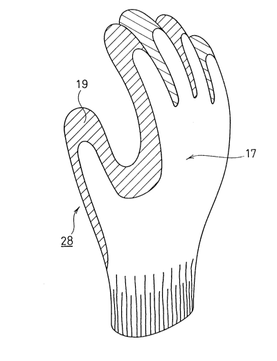
permeability. FIG. 2 shows the glove as removed from the setting
hand block 21. As can be seen from the figure, the glove obtained
is closely akin in shape to human hand, involves less bagginess in
2055250
the palm portion, can readily fit on hand, and is comfortable to
wear.
In the foregoing example, stock solution is deposited on the
fiber-made glove according to the heat sensitive process.
Alternatively, some other technique, such as coagulant dip process,
may be employed for the purpose.