Language selection

Search

Patent 2055256 Summary

Third-party information liability

Some of the information on this Web page has been provided by external sources. The Government of Canada is not responsible for the accuracy, reliability or currency of the information supplied by external sources. Users wishing to rely upon this information should consult directly with the source of the information. Content provided by external sources is not subject to official languages, privacy and accessibility requirements.

Claims and Abstract availability

Any discrepancies in the text and image of the Claims and Abstract are due to differing posting times. Text of the Claims and Abstract are posted:

  • At the time the application is open to public inspection;
  • At the time of issue of the patent (grant).
(12) Patent Application: (11) CA 2055256
(54) English Title: VALVE ARRANGEMENTS
(54) French Title: AGENCEMENT DE VANNES
Status: Deemed Abandoned and Beyond the Period of Reinstatement - Pending Response to Notice of Disregarded Communication
Bibliographic Data
(51) International Patent Classification (IPC):
  • B60T 15/36 (2006.01)
  • B60T 11/32 (2006.01)
(72) Inventors :
  • LANGLEY, KEITH W. (United Kingdom)
(73) Owners :
  • WESTINGHOUSE BRAKE AND SIGNAL HOLDINGS LIMITED
(71) Applicants :
  • WESTINGHOUSE BRAKE AND SIGNAL HOLDINGS LIMITED (United Kingdom)
(74) Agent: ROGERS & SCOTT
(74) Associate agent:
(45) Issued:
(22) Filed Date: 1991-11-12
(41) Open to Public Inspection: 1992-05-27
Availability of licence: N/A
Dedicated to the Public: N/A
(25) Language of filing: English

Patent Cooperation Treaty (PCT): No

(30) Application Priority Data:
Application No. Country/Territory Date
9025638.9 (United Kingdom) 1990-11-26

Abstracts

English Abstract


ABSTRACT OF THE DISCLOSURE
A valve arrangement comprises an inlet port (?), an
outlet port (?), a valve member (?) normally adopting a
valve arrangement open position in which fluid flow from
the inlet port (?) to the outlet port (?) is permitted
via a choke (?), and a fluid chamber (?). The inlet port
(?) is connected via another choke (?) to supply fluid to
the fluid chamber (?) to urge the valve member (?) to a
valve arrangement closed position. The two chokes (?
?) determine that upon flow of fluid from the inlet port
(?) to the outlet port (?) the fluid pressure in the
fluid chamber (?) tends to rise more slowly than the
fluid pressure at the outlet port (?) and so the valve
member (?) is urged to remain in the valve arrangement
open position by the effect of the fluid pressure at the
outlet port (?). If this fluid pressure is insufficient,
either because of an existing rupture downstream of the
valve arrangement or because such a rupture occurs, the
fluid pressure in the fluid chamber (?) asserts itself to
move the valve member (?) to the valve arrangement closed
position.


Claims

Note: Claims are shown in the official language in which they were submitted.

WHAT IS CLAIMED IS:
1. A valve arrangement comprising an inlet port, an
outlet port, a valve member normally adopting a valve
arrangement open position in which fluid flow from the
inlet port to the outlet port is permitted, and a fluid
chamber, fluid pressure in this chamber being effective
for urging the valve member to a valve arrangement closed
position, the inlet port being connected to supply fluid
to the fluid chamber and, in the valve arrangement open
position of the valve member, to the outlet port via a
choke arrangement determining that upon flow of fluid
from the inlet port to the outlet port the fluid pressure
in the fluid chamber tends to rise more slowly than the
fluid pressure at the outlet port, the valve member being
urged to remain in the valve arrangement open position by
the effect of the fluid pressure at the outlet port
whereby if the fluid pressure at the outlet port is
insufficiently high the fluid pressure in the fluid
chamber asserts itself to move the valve member to the
valve arrangement closed position.
2. A valve arrangement according to claim 1, wherein in
its valve arrangement closed position the valve member
closes completely communication between the inlet port
and the outlet port.
3. A valve arrangement according to claim 1 and
comprising a bleed line permitting fluid bleed past the
valve member in the valve arrangement closed position.
4. A valve arrangement according to claim 1 and
comprising a bypass, by passing the choke arrangement,
connecting the fluid chamber with the inlet port, this
bypass including a check valve allowing fluid to flow
only in the direction from the fluid chamber to the inlet
port.

5. A valve arrangement according to claim 1, wherein
the choke arrangement comprises a first choke through
which the inlet port is connected to the fluid chamber
and a second choke through which the inlet port is open
to the outlet port.
6. A valve arrangement according to claim 1, wherein
the valve member is biased by resilient means to its
valve arrangement open position.

Description

Note: Descriptions are shown in the official language in which they were submitted.


2~2~6
-- 1
AL~JE ARRANGEMENTS
BACKGROUND OF THE INVENTION
Field of the Invention:
This invention relates to valve arrangements for
automatically affecting flow of fluid in a fluid flow
line in the event of change in pressure of the fluid
flowing in the line. The invention is particularly
concerned with such arrangements for use in the pneumatic
brake lines of multiple-unit vehicle air brake systems.
Description of the Prior Art:
In a typical multiple-unit vehicle air brake system there
are included in the pneumatic brake lines to the
individual braked bogies, so-called "hose protection
chokes". If a brake line ruptures downstream of any one
of these chokes, the resulting escape of air is limited
to that permitted by the size of the choke orifice. This
orifice must, of course, be sufficiently large to allow,
in normal circumstances, sufficient air flow to achieve
braking. However, the loss of air permitted by such a
relatively large-orificed choke in the event of rupture
may be too high for satisfactory operation of the
remainder of the system. This is particularly so if the
number of units is small, say two or three, or indeed if
a brake system is that of a single vehicle.
~UMMARY OF THE INVENTION
According to the present invention there is provided a
valve arrangement comprising an inlet port, an outlet
port, a valve member normally adopting a valve
arrangement open position in which fluid flow from the
inlet port to the outlet port is permitted, and a fluid
chamber, fluid pressure in this chamber being effective
for urging the valve member to a valve arrangement closed
position, the inlet port being connected to supply fluid
to the fluid chamber and, in the valve arrangement open
position of the valve member, to the outlet port via a
choke arrangement determining that upon flow of fluid

2 ~
from the inlet port to the outlet port the fluid pressure
in the fluid chamber tends to rise more slowly than the
fluid pressure at the outlet port, the valve member being
urged to remain in the valve arrangement open position by
the effect of tha fluid pressure at the outlet port
whereby if the fluid pressure at the outlet port is
insufficiently high the fluid pressure in the fluid
chamber asserts itself to move the valve member to the
valve arrangement closed position.
In use in a fluid flow line with the inlet port connected
to a source of fluid pressure to be supplied to the inlet
port, this valve arrangement operates automatically to
close in the event of sufficient loss of pressure at the
outlet port so that if, for example, the flow line is
part of a vehicle air brake system, the system upstream
of the valve arrangement is protected from the effects of
a rupture downstream of the arrangement.
The valve arrangement when closed can either close
completely the communication between the inlet and outlet
ports, or if desired the valve arrangement can include a
bleed line permitting fluid bleed past the valve member
in the valve arrangement closed position, sufficient to
give an indication that the closed position has been
reached but insufficient significantly to reduce the
~5 protection given by the closed valve arrangement.
BRIEF DESCRIPTION OF THE DRAWING
For a better understanding of the invention and to show
how the same may be carried into effect reference will
now be made, by way of example, to the accompanying
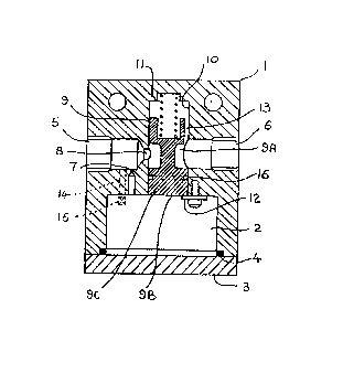
drawing, in which the single Figure is a sectional side
view of a valve arrangement.
DESCRIPTION OF ~HE PREFERRED EMBODIMENTS
The valve arrangement shown in the Figure has a body 1 in
which there is a fluid chamber 2 closed by an end cap 3
acting on a sealing rlng 4, and tapped co-axial inlet and
.

2 ~
-- 3 --
ou-tlet ports 5 and 6. The inlet port 5 is in
communication with the chamber 2 via a first choke 7.
In the open condition of the valve arrangement
illustrated the inlet port 5 is in communication with the
outlet port 6 via a second choke 8 at the inner end of
the port 5, downstream of the first choke 7, and a groove
9A in a valve member 9.
The valve member 9 is slidable in a bore 10 which is
transverse of the ports 5 and 6 and opens into the
chamber 2. A spring 11 acts to hold the valve member 9
in the open position, against a stop 12, with -the inner
face 9B of the valve member 9 exposed to the chamber 2.
In normal operation with, for example, the inlet port 5
connected to an air pressure supply and the outlet port
6 connected to operate the brakes on a vehicle bogie,
upon such operation air flows from port S to port 6 via
second choke 8 and groove 9A. Air also flows via first
choke 7 into chamber 2 to apply pressure to the inner
face 9B of the valve member 9. The relative sizes of the
chokes 7 and 8 are selected to ensure that the pressure
in the chamber 2 rises more slowly than the pressure at
the outlet port 6. The part of the bore 10 housing the
spring 11 is open to the outlet port 6 via a passage 13
defined by a flat on the valve member 9 and the pressure
at the outlet port 6 acts, with the spring 11, on the
valve membar 9 in the sense to oppose the action thereon
of the pressure in the chamber 2 and the valve member 9
is held in the illustrated open position. However, if
there is a rupture downstream of the outlet port 6 so
that the pressure in the outlet port 6 does not increase
sufficiently to overcome the action on the valve member
9 of the rising pressure in the chamber 2, or, upon a
rupture occurring, drops off so as to cease to overcome
the chamber 2 pressure, the pressure in the chamber 2
moves the valve member 9 against the action of the spring
11 so that a full diameter portion 9C of the valve member

2 ~
9 closes the communication between the ports 5 and 6. In
this closed condition, therefore, the port 5 is closed at
the valve arrangement.
With the valve member 9 in the illustrated open position,
upon reduction of air pressure at the inlet port 5 air
will flow from the outlet port 6 to the inlet port 5 and
air will also evacuate from the chamber 2 via the choke
7. If ~ecessary there can be provided, as shown by
dotted lines in the Figure, a bypass 14, by passing the
choke 7, connecting the chamber 2 with the inlet port 5
and including a check valve 15 allowing flow only in the
direction from the chamber 2 to the port 5. This bypass
would be sized to achieve a sufficiently quick flow of
air from the chamber 2 to the port 5 to ensure that the
valve member 9 does not move to the closed position.
Also shown in the Figure is an annular groove 16 in the
full diameter portion 9C of the valve member 9. This
groove 16 is provided, if so desired, as a bleed line to
give a small leakage of fluid from the port 5 in the
valve arrangement closed condition, sufficient to give an
indication that the closed condition has been reached,
but insufficient significantly to reduce the effect of
the valve arrangement closing.
It will be appreciated that if incorporated in the
pneumatic brake line to an individual braked bogie of a
vehicle air brake system, the valve arrangement described
- will close, upon (or during) operation of the brakes of
the bogie, if there is a rupture in the system downstream
of the valve arrangement (or if a rupture occurs) thereby
to protect the system upstream of the valve arrangement
from the effects of the rupture.

Representative Drawing
A single figure which represents the drawing illustrating the invention.
Administrative Status

2024-08-01:As part of the Next Generation Patents (NGP) transition, the Canadian Patents Database (CPD) now contains a more detailed Event History, which replicates the Event Log of our new back-office solution.

Please note that "Inactive:" events refers to events no longer in use in our new back-office solution.

For a clearer understanding of the status of the application/patent presented on this page, the site Disclaimer , as well as the definitions for Patent , Event History , Maintenance Fee  and Payment History  should be consulted.

Event History

Description Date
Inactive: IPC from MCD 2006-03-11
Time Limit for Reversal Expired 1994-05-14
Application Not Reinstated by Deadline 1994-05-14
Deemed Abandoned - Failure to Respond to Maintenance Fee Notice 1993-11-12
Inactive: Adhoc Request Documented 1993-11-12
Application Published (Open to Public Inspection) 1992-05-27

Abandonment History

Abandonment Date Reason Reinstatement Date
1993-11-12
Owners on Record

Note: Records showing the ownership history in alphabetical order.

Current Owners on Record
WESTINGHOUSE BRAKE AND SIGNAL HOLDINGS LIMITED
Past Owners on Record
KEITH W. LANGLEY
Past Owners that do not appear in the "Owners on Record" listing will appear in other documentation within the application.
Documents

To view selected files, please enter reCAPTCHA code :


To view images, click a link in the Document Description column. To download the documents, select one or more checkboxes in the first column and then click the "Download Selected in PDF format (Zip Archive)" or the "Download Selected as Single PDF" button.

List of published and non-published patent-specific documents on the CPD .

If you have any difficulty accessing content, you can call the Client Service Centre at 1-866-997-1936 or send them an e-mail at CIPO Client Service Centre.


Document
Description 
Date
(yyyy-mm-dd) 
Number of pages   Size of Image (KB) 
Abstract 1992-05-26 1 27
Claims 1992-05-26 2 49
Drawings 1992-05-26 1 17
Descriptions 1992-05-26 4 170
Representative drawing 1996-04-24 1 12