Sélection de la langue

Search

Sommaire du brevet 2055256 

Énoncé de désistement de responsabilité concernant l'information provenant de tiers

Une partie des informations de ce site Web a été fournie par des sources externes. Le gouvernement du Canada n'assume aucune responsabilité concernant la précision, l'actualité ou la fiabilité des informations fournies par les sources externes. Les utilisateurs qui désirent employer cette information devraient consulter directement la source des informations. Le contenu fourni par les sources externes n'est pas assujetti aux exigences sur les langues officielles, la protection des renseignements personnels et l'accessibilité.

Disponibilité de l'Abrégé et des Revendications

L'apparition de différences dans le texte et l'image des Revendications et de l'Abrégé dépend du moment auquel le document est publié. Les textes des Revendications et de l'Abrégé sont affichés :

  • lorsque la demande peut être examinée par le public;
  • lorsque le brevet est émis (délivrance).
(12) Demande de brevet: (11) CA 2055256
(54) Titre français: AGENCEMENT DE VANNES
(54) Titre anglais: VALVE ARRANGEMENTS
Statut: Réputée abandonnée et au-delà du délai pour le rétablissement - en attente de la réponse à l’avis de communication rejetée
Données bibliographiques
(51) Classification internationale des brevets (CIB):
  • B60T 15/36 (2006.01)
  • B60T 11/32 (2006.01)
(72) Inventeurs :
  • LANGLEY, KEITH W. (Royaume-Uni)
(73) Titulaires :
  • WESTINGHOUSE BRAKE AND SIGNAL HOLDINGS LIMITED
(71) Demandeurs :
  • WESTINGHOUSE BRAKE AND SIGNAL HOLDINGS LIMITED (Royaume-Uni)
(74) Agent: ROGERS & SCOTT
(74) Co-agent:
(45) Délivré:
(22) Date de dépôt: 1991-11-12
(41) Mise à la disponibilité du public: 1992-05-27
Licence disponible: S.O.
Cédé au domaine public: S.O.
(25) Langue des documents déposés: Anglais

Traité de coopération en matière de brevets (PCT): Non

(30) Données de priorité de la demande:
Numéro de la demande Pays / territoire Date
9025638.9 (Royaume-Uni) 1990-11-26

Abrégés

Abrégé anglais


ABSTRACT OF THE DISCLOSURE
A valve arrangement comprises an inlet port (?), an
outlet port (?), a valve member (?) normally adopting a
valve arrangement open position in which fluid flow from
the inlet port (?) to the outlet port (?) is permitted
via a choke (?), and a fluid chamber (?). The inlet port
(?) is connected via another choke (?) to supply fluid to
the fluid chamber (?) to urge the valve member (?) to a
valve arrangement closed position. The two chokes (?
?) determine that upon flow of fluid from the inlet port
(?) to the outlet port (?) the fluid pressure in the
fluid chamber (?) tends to rise more slowly than the
fluid pressure at the outlet port (?) and so the valve
member (?) is urged to remain in the valve arrangement
open position by the effect of the fluid pressure at the
outlet port (?). If this fluid pressure is insufficient,
either because of an existing rupture downstream of the
valve arrangement or because such a rupture occurs, the
fluid pressure in the fluid chamber (?) asserts itself to
move the valve member (?) to the valve arrangement closed
position.

Revendications

Note : Les revendications sont présentées dans la langue officielle dans laquelle elles ont été soumises.


WHAT IS CLAIMED IS:
1. A valve arrangement comprising an inlet port, an
outlet port, a valve member normally adopting a valve
arrangement open position in which fluid flow from the
inlet port to the outlet port is permitted, and a fluid
chamber, fluid pressure in this chamber being effective
for urging the valve member to a valve arrangement closed
position, the inlet port being connected to supply fluid
to the fluid chamber and, in the valve arrangement open
position of the valve member, to the outlet port via a
choke arrangement determining that upon flow of fluid
from the inlet port to the outlet port the fluid pressure
in the fluid chamber tends to rise more slowly than the
fluid pressure at the outlet port, the valve member being
urged to remain in the valve arrangement open position by
the effect of the fluid pressure at the outlet port
whereby if the fluid pressure at the outlet port is
insufficiently high the fluid pressure in the fluid
chamber asserts itself to move the valve member to the
valve arrangement closed position.
2. A valve arrangement according to claim 1, wherein in
its valve arrangement closed position the valve member
closes completely communication between the inlet port
and the outlet port.
3. A valve arrangement according to claim 1 and
comprising a bleed line permitting fluid bleed past the
valve member in the valve arrangement closed position.
4. A valve arrangement according to claim 1 and
comprising a bypass, by passing the choke arrangement,
connecting the fluid chamber with the inlet port, this
bypass including a check valve allowing fluid to flow
only in the direction from the fluid chamber to the inlet
port.

5. A valve arrangement according to claim 1, wherein
the choke arrangement comprises a first choke through
which the inlet port is connected to the fluid chamber
and a second choke through which the inlet port is open
to the outlet port.
6. A valve arrangement according to claim 1, wherein
the valve member is biased by resilient means to its
valve arrangement open position.

Description

Note : Les descriptions sont présentées dans la langue officielle dans laquelle elles ont été soumises.

2~2~6
-- 1
AL~JE ARRANGEMENTS
BACKGROUND OF THE INVENTION
Field of the Invention:
This invention relates to valve arrangements for
automatically affecting flow of fluid in a fluid flow
line in the event of change in pressure of the fluid
flowing in the line. The invention is particularly
concerned with such arrangements for use in the pneumatic
brake lines of multiple-unit vehicle air brake systems.
Description of the Prior Art:
In a typical multiple-unit vehicle air brake system there
are included in the pneumatic brake lines to the
individual braked bogies, so-called "hose protection
chokes". If a brake line ruptures downstream of any one
of these chokes, the resulting escape of air is limited
to that permitted by the size of the choke orifice. This
orifice must, of course, be sufficiently large to allow,
in normal circumstances, sufficient air flow to achieve
braking. However, the loss of air permitted by such a
relatively large-orificed choke in the event of rupture
may be too high for satisfactory operation of the
remainder of the system. This is particularly so if the
number of units is small, say two or three, or indeed if
a brake system is that of a single vehicle.
~UMMARY OF THE INVENTION
According to the present invention there is provided a
valve arrangement comprising an inlet port, an outlet
port, a valve member normally adopting a valve
arrangement open position in which fluid flow from the
inlet port to the outlet port is permitted, and a fluid
chamber, fluid pressure in this chamber being effective
for urging the valve member to a valve arrangement closed
position, the inlet port being connected to supply fluid
to the fluid chamber and, in the valve arrangement open
position of the valve member, to the outlet port via a
choke arrangement determining that upon flow of fluid

2 ~
from the inlet port to the outlet port the fluid pressure
in the fluid chamber tends to rise more slowly than the
fluid pressure at the outlet port, the valve member being
urged to remain in the valve arrangement open position by
the effect of tha fluid pressure at the outlet port
whereby if the fluid pressure at the outlet port is
insufficiently high the fluid pressure in the fluid
chamber asserts itself to move the valve member to the
valve arrangement closed position.
In use in a fluid flow line with the inlet port connected
to a source of fluid pressure to be supplied to the inlet
port, this valve arrangement operates automatically to
close in the event of sufficient loss of pressure at the
outlet port so that if, for example, the flow line is
part of a vehicle air brake system, the system upstream
of the valve arrangement is protected from the effects of
a rupture downstream of the arrangement.
The valve arrangement when closed can either close
completely the communication between the inlet and outlet
ports, or if desired the valve arrangement can include a
bleed line permitting fluid bleed past the valve member
in the valve arrangement closed position, sufficient to
give an indication that the closed position has been
reached but insufficient significantly to reduce the
~5 protection given by the closed valve arrangement.
BRIEF DESCRIPTION OF THE DRAWING
For a better understanding of the invention and to show
how the same may be carried into effect reference will
now be made, by way of example, to the accompanying
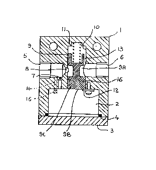
drawing, in which the single Figure is a sectional side
view of a valve arrangement.
DESCRIPTION OF ~HE PREFERRED EMBODIMENTS
The valve arrangement shown in the Figure has a body 1 in
which there is a fluid chamber 2 closed by an end cap 3
acting on a sealing rlng 4, and tapped co-axial inlet and
.

2 ~
-- 3 --
ou-tlet ports 5 and 6. The inlet port 5 is in
communication with the chamber 2 via a first choke 7.
In the open condition of the valve arrangement
illustrated the inlet port 5 is in communication with the
outlet port 6 via a second choke 8 at the inner end of
the port 5, downstream of the first choke 7, and a groove
9A in a valve member 9.
The valve member 9 is slidable in a bore 10 which is
transverse of the ports 5 and 6 and opens into the
chamber 2. A spring 11 acts to hold the valve member 9
in the open position, against a stop 12, with -the inner
face 9B of the valve member 9 exposed to the chamber 2.
In normal operation with, for example, the inlet port 5
connected to an air pressure supply and the outlet port
6 connected to operate the brakes on a vehicle bogie,
upon such operation air flows from port S to port 6 via
second choke 8 and groove 9A. Air also flows via first
choke 7 into chamber 2 to apply pressure to the inner
face 9B of the valve member 9. The relative sizes of the
chokes 7 and 8 are selected to ensure that the pressure
in the chamber 2 rises more slowly than the pressure at
the outlet port 6. The part of the bore 10 housing the
spring 11 is open to the outlet port 6 via a passage 13
defined by a flat on the valve member 9 and the pressure
at the outlet port 6 acts, with the spring 11, on the
valve membar 9 in the sense to oppose the action thereon
of the pressure in the chamber 2 and the valve member 9
is held in the illustrated open position. However, if
there is a rupture downstream of the outlet port 6 so
that the pressure in the outlet port 6 does not increase
sufficiently to overcome the action on the valve member
9 of the rising pressure in the chamber 2, or, upon a
rupture occurring, drops off so as to cease to overcome
the chamber 2 pressure, the pressure in the chamber 2
moves the valve member 9 against the action of the spring
11 so that a full diameter portion 9C of the valve member

2 ~
9 closes the communication between the ports 5 and 6. In
this closed condition, therefore, the port 5 is closed at
the valve arrangement.
With the valve member 9 in the illustrated open position,
upon reduction of air pressure at the inlet port 5 air
will flow from the outlet port 6 to the inlet port 5 and
air will also evacuate from the chamber 2 via the choke
7. If ~ecessary there can be provided, as shown by
dotted lines in the Figure, a bypass 14, by passing the
choke 7, connecting the chamber 2 with the inlet port 5
and including a check valve 15 allowing flow only in the
direction from the chamber 2 to the port 5. This bypass
would be sized to achieve a sufficiently quick flow of
air from the chamber 2 to the port 5 to ensure that the
valve member 9 does not move to the closed position.
Also shown in the Figure is an annular groove 16 in the
full diameter portion 9C of the valve member 9. This
groove 16 is provided, if so desired, as a bleed line to
give a small leakage of fluid from the port 5 in the
valve arrangement closed condition, sufficient to give an
indication that the closed condition has been reached,
but insufficient significantly to reduce the effect of
the valve arrangement closing.
It will be appreciated that if incorporated in the
pneumatic brake line to an individual braked bogie of a
vehicle air brake system, the valve arrangement described
- will close, upon (or during) operation of the brakes of
the bogie, if there is a rupture in the system downstream
of the valve arrangement (or if a rupture occurs) thereby
to protect the system upstream of the valve arrangement
from the effects of the rupture.

Dessin représentatif
Une figure unique qui représente un dessin illustrant l'invention.
États administratifs

2024-08-01 : Dans le cadre de la transition vers les Brevets de nouvelle génération (BNG), la base de données sur les brevets canadiens (BDBC) contient désormais un Historique d'événement plus détaillé, qui reproduit le Journal des événements de notre nouvelle solution interne.

Veuillez noter que les événements débutant par « Inactive : » se réfèrent à des événements qui ne sont plus utilisés dans notre nouvelle solution interne.

Pour une meilleure compréhension de l'état de la demande ou brevet qui figure sur cette page, la rubrique Mise en garde , et les descriptions de Brevet , Historique d'événement , Taxes périodiques et Historique des paiements devraient être consultées.

Historique d'événement

Description Date
Inactive : CIB de MCD 2006-03-11
Le délai pour l'annulation est expiré 1994-05-14
Demande non rétablie avant l'échéance 1994-05-14
Réputée abandonnée - omission de répondre à un avis sur les taxes pour le maintien en état 1993-11-12
Inactive : Demande ad hoc documentée 1993-11-12
Demande publiée (accessible au public) 1992-05-27

Historique d'abandonnement

Date d'abandonnement Raison Date de rétablissement
1993-11-12
Titulaires au dossier

Les titulaires actuels et antérieures au dossier sont affichés en ordre alphabétique.

Titulaires actuels au dossier
WESTINGHOUSE BRAKE AND SIGNAL HOLDINGS LIMITED
Titulaires antérieures au dossier
KEITH W. LANGLEY
Les propriétaires antérieurs qui ne figurent pas dans la liste des « Propriétaires au dossier » apparaîtront dans d'autres documents au dossier.
Documents

Pour visionner les fichiers sélectionnés, entrer le code reCAPTCHA :


Pour visualiser une image, cliquer sur un lien dans la colonne description du document. Pour télécharger l'image (les images), cliquer l'une ou plusieurs cases à cocher dans la première colonne et ensuite cliquer sur le bouton "Télécharger sélection en format PDF (archive Zip)" ou le bouton "Télécharger sélection (en un fichier PDF fusionné)".

Liste des documents de brevet publiés et non publiés sur la BDBC .

Si vous avez des difficultés à accéder au contenu, veuillez communiquer avec le Centre de services à la clientèle au 1-866-997-1936, ou envoyer un courriel au Centre de service à la clientèle de l'OPIC.


Description du
Document 
Date
(aaaa-mm-jj) 
Nombre de pages   Taille de l'image (Ko) 
Page couverture 1992-05-27 1 15
Abrégé 1992-05-27 1 27
Revendications 1992-05-27 2 49
Dessins 1992-05-27 1 17
Description 1992-05-27 4 170
Dessin représentatif 1996-04-25 1 12