Language selection

Search

Patent 2055276 Summary

Third-party information liability

Some of the information on this Web page has been provided by external sources. The Government of Canada is not responsible for the accuracy, reliability or currency of the information supplied by external sources. Users wishing to rely upon this information should consult directly with the source of the information. Content provided by external sources is not subject to official languages, privacy and accessibility requirements.

Claims and Abstract availability

Any discrepancies in the text and image of the Claims and Abstract are due to differing posting times. Text of the Claims and Abstract are posted:

  • At the time the application is open to public inspection;
  • At the time of issue of the patent (grant).
(12) Patent Application: (11) CA 2055276
(54) English Title: EXERCISE DEVICE
(54) French Title: APPAREIL D'EXERCICE
Status: Dead
Bibliographic Data
(51) International Patent Classification (IPC):
  • A63B 21/00 (2006.01)
  • A63B 23/12 (2006.01)
  • A63B 21/062 (2006.01)
  • A63B 23/00 (2006.01)
(72) Inventors :
  • BASILE, VINCENT FRANK (Australia)
(73) Owners :
  • BASILE, VINCENT FRANK (Australia)
(71) Applicants :
(74) Agent: CASSAN MACLEAN
(74) Associate agent:
(45) Issued:
(22) Filed Date: 1991-11-13
(41) Open to Public Inspection: 1992-05-14
Examination requested: 1998-11-09
Availability of licence: N/A
(25) Language of filing: English

Patent Cooperation Treaty (PCT): No

(30) Application Priority Data:
Application No. Country/Territory Date
PK3336 Australia 1990-11-13

Abstracts

English Abstract


ABSTRACT
An exercise machine which includes a base which supports the user.
Mounted on the base and to be manipulated by the user is a pair of arm
assemblies, with each assembly including a lever which pivots about an
axis extending generally transverse of the user. Mounted on the lever is
a further lever or shaft, which further lever or shaft is also moved
angularly by the user. Accordingly the user performs two exercise
movements which include movement about the axis extending transverse of
the user, and a second axis which may extend parallel to the first axis
or generally normal thereto.


Claims

Note: Claims are shown in the official language in which they were submitted.


- 5 -
THE EMBODIMENTS OF THE INVENTION IN WHICH AN EXCLUSIVE PROPERTY
OR PRIVILEGE IS CLAIMED ARE DEFINED AS FOLLOWS:
l. An exercise machine comprising:
a base frame;
an arm assembly mounted on the frame and including, a lever
pivotally mounted on said frame for pivoting movement about a first axis,
a movement transfer member, mounted on said lever for angular movement
relative thereto about a second axis, handle means on said member to be
gripped by a user to apply forces thereto to cause pivoting of said lever
and angular movement of said member;
means to resist movement of said levers; and
support means to position the user s body so that said axes are
positioned to be coaxial with normal pivoting axes of the user s body.
2. The machine of claim l, wherein said support means and said
first lever are arranged so that said first axis extends in a direction
transverse of the user and said movement transfer member is a shaft
mounted for rotation about said second axis, said second axis being
generally normal to said first axis, and wherein said machine further
includes a handle fixed to said shaft to be gripped by a user to cause
rotation-thereof by rotation of the user s wrist about the longitudinal
axis of the user s lower arm.
3. The machine of claim 2, wherein said shaft is mounted for
longitudinal movement along said second axis.
4. The machine of claim 2, wherein the resistance means includes
a first resistance means to apply a resistance force to movement of said
lever, and a second resistance means to apply a resistance force to the
rotation of said shaft.
5. The machine of claim l, wherein said support means is arranged
relative to said first axis so that said first axis extends generally
transverse of the user, and said movement transfer member is a second
lever pivotally mounted on said first lever for rotation about said
second axis.
6. The machine of claim 5, wherein said second axis is normal to
said first axis.
7. The machine of claim 5, wherein said second axis is parallel
to said first axis but spaced therefrom.
8. The machine of claim 5, wherein the resistance means includes
a first resistance means to resist movement of said first lever, and
second resistance means to resist movement of said second lever.

LMM/513t


- 6 -
9. The machine of claim 8, further including forced transfer
means coupling said first lever with said resistance means to vary the
force applied to said first lever in accordance with its angular
deflection.
10. An exercise machine substantially as hereinbefore described
with reference to Figures 1 to 5 of the accompanying drawings, or with
reference to Figure 6 or Figure 7 of the accompanying drawings.
Description

Note: Descriptions are shown in the official language in which they were submitted.


TECHNICAL FIELD
The present invention relates to an exercise device and more
particularly to an exercise device which permits the user to perform two
exercise motions.
BACKGROUND OF THE INVENTION
Known exercise devices such as rowing machines and some exercise
bicycles, which in addition to providing a leg function~ enable the user
to exercise the arms and the upper chest by providing pivoted handles
which the user grips and causes angular reciprocation of the handles.
There are also known machines which exercise the user's legs by providing
vertically reciprocal foot pads to which the user applies alternate
pressure. In comblnation with these foot pads there is provided pivoted
levers which are angularly oscillated by the user.
OBJECT OF THE INVENTION
The above descrlbed exerclse devlces do not provide for
slmultaneous exercise employlng rotation of the user's wrists and angular
movement of the user's arms.
It is the ob~ect of the present lnvent~on to overcome or
substant~ally ameliorate the above disadvantages.
SUMMARY OF THE INVENTION
There is disclosed herein an exercise machine compris~ng:
a base frame;
an arm assembly mounted on the frame and ~ncluding, a lever
plvotally mounted on sa~d frame for pivot~ng movement about a first axis,
a movement transfer member, mounted on sald lever for angular movement
relat~ve thereto about a second axls, handle means on sa~d member to be
gr~pped by a user to apply ~orces thereto to cause p~vot~ng of sa~d lever
and angular movement of sald member;
means to resist movement of sald levers; and
support means to posltlon the user's body so that said axes are
positioned to ~e coaxlal with normal plvotlng axes of the user's body.
BRIEF D5CRIPTION OF THE DRA~INGS
Preferred forms of the present invention will now be described by
way of example with reference to the accompanying drawings wherein
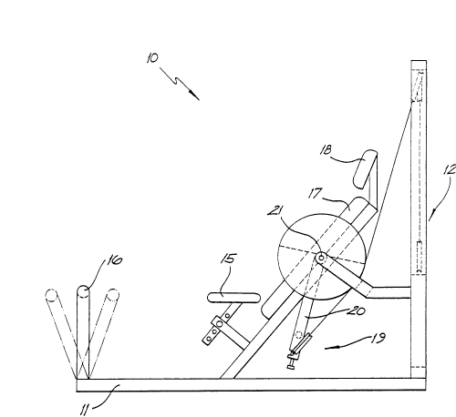
Figure 1 ls a schematic side elevation of an exercise machine;
Figure 2 ls a schematic end elevation of the exercise machine of
Figure l;


LMM/513t

Figure 3 is a schematic perspective view of the resistance portion
of the exercise machine of Figure l;
Figure 4 is a schematic top plan view of a handle portion of the
machine of Figure l;
Figure 5 is a schematic perspective view of a modification of the
exercise machine of Figure l;
Figure 6 is a schematic perspective view of a second exercise
machine; and
Figure 7 is a schematic perspect;ve v;ew of a th;rd exercise
mach;ne.
DESCRIPTION OF THE PREFERRED EMBODIMENTS
In Figures 1 to 4 there is schematically depicted an exerc;se
machine (bicep-suplnator~ 10. The exercise machine 10 has a base frame
11 which supports a weight stack 12. The weight stack 12 ls received by
a pair of vertically extending guide rods 13 which guide the weight stack
12 in its vertical movement. The weight stack 12 consists of a plurality
Of weights 14 Wh~ch may be select~vely coupled together to be lifted by
the user of the machine 10.
Mounted on the frame 11 is an adjustable seat 15 and an adjustable
footrest 16. There ~S also provlded a back sUpport 17 and a head rest 18.
Located on ~ach side of the seat 15 are arm assemblies 19 with
each assembly 19 be~ng assoc~ated W~th the we~ght stack 12. The arm
assemblles lg are man~pulated by the user.
Each arm assembly 19 lncludes a prlmary lever 20 which ls pivotally
mounted for rotation about a horizontal axis 21 extending generally
transverse of the user. Mounted on the extremity of each arm 20 is a
shaft 21 which is supported for rotation about its longitudlnal axis.
Attached to each shaft 21 ls a hand grip 22 whlch the user grips. The
shaft 22 is also slidlngly mounted for longitudinal movement along its
axis and ls biased to a predetermined position by means of the spring
23. More part~cularly the shaft 21 has splines 24 which are recelved
within a splined passage passing through the hub 25. Mounted on the hub
25 is a pulley 26. Extending from and attached to the pulley 26 is an
elongated flexible element 27 which can be a belt chain or cable. The
element 27 passes around pulleys 28 2~ and 30 to pass around a final
pulley 31.
Also at~ached to the arm 20 is a counter-weight 34.
In operation of the above described device 10 the user grips the
handle 22 and rotates the shaft 21 about its longitudinal axis. This

LMMf513t

causes the associated weight stack 12 to rise. In addition to that
movement of the arm 20 in the direction of the arrow 32 again causes the
associated weight stack 12 to rise. Accordingly the weight stack lZ
provides resistance to both movement of the shaft 21 and the arm 20.
It should be appreciated that both arm assemblies 19 are
operatively associated with the weight stack 12.
In this embodiment the user from a seated position reaches down
and grabs the handles 22 and pulls them upward while turning their wrist
about the longitudinal axis of the lower part of the arm.
It should be appreciated that pivot;ng of the lever 20 occurs about
a normal pivot axis of the body and that the machine 10 could be
modified to enable the user to perform a twisting exercise with a
curling exercise. This would be ach~eved by raising the arm assemblies
19 and prov~ ding an el bow rest.
Additionally the exercises performed on the machine lo could be
reversed by altering the effect of the element 27 so that the weight
stack 12 was raised by the reverse movement.
In Figure 5 there ~s schemat~cally depicted a still further
modificat~on of the machine 10. In this particular embodiment the
resistance applied to the handle 22 ~s separated from the resistance
applied to the lever 20. In this particular embodiment the element 27
is associated with the pulley 28 so that movement of the arm 20 does not
influence or alternatively has minimum influence on the resistance
applied to the handle 22. Also fixed to the arm 20 is a pulley 33 to
which there is attached an elongated flexible element 34. The element 34
passes around a pulley 35 to a final pulley 36 to which may be attached a
we~ght stack. The pulley 33 may be of a circular configuration or
whatever shape desired in order to vary the resistance applied to the arm
20.
As a still further modificat~on the elements 27 and 34 may be
operatively associated with the same weight stack. However in this
particular embodiment the pulleys 31 and 36 are operatively associated
w~th separate weight stacks.
In Figure 6 there is schematically depicted an exercise machine
70. The machlne 70 ~s adapted to perform a chest press and fly
operation . The mach~ne 70 has a pivotally supported arm 71 for rotation
about an axis 72. Pivotally mounted on the arm 71 is a further arm 83
which pivots about an axis 73. The arm 83 has a handle 74 which is
gripped by the user.

LMM/513t

Also mounted on the arm 71 is a pulley 75 about which there passes
an elongated flexible element 76. The element 76 is attached to the arm
72 so as to move with the handle 74 upon operation by the user. The
element 76 passes around pulleys 77 to a we;ght stack not ;llustrated.
S However the weight stack would function in the same manner as the stack
12.
Fixed to the frame is a pulley 81 around which an element 79
passes. The element 79 is attached to the arm 71. The element 79
extends to the same or a separate weight stack.
In use of the above described machine 70, the user causes pivot;ng
of the lever 71 in the direction of the arrow A and pivoting of the lever
72 in the direction of the arrow B. The element then causes movement of
their associated weight stacks.
In Figure 7 there is schemat~cally depicted an exercise machine 50
lS which is adapted to perform a "s~t-up" and ~abdominal crunch" type
functions.
The machine 50 has been allocated the same numerals as the machine
S0 of Figure 7. However as can be seen from Figure 8, the lever 72
p1vots about an ax~s 51 wh~ch is normal to the axls 73 of Figure 6.
In Use of the machine S0, the user not only causes operation of the
mach~ne lO0 by pivot~ng movement at the hip, but also pivoting movement
about an ax~s pass~ng through the back of the user.
F~xed to the arm ~s a pulley 52 to which ~s attached an elongated
flex~ble element 53. The element 53 passes around a pulley 54 to a f~nal
pulley 55. The pulley 55 would be attached to a we~ght stack. In this
particular embodiment, the element 76 passes around a pulley 56 to be
also attached to the pulley 55 and ~n effect to be integral w~th the
element 53. However the elements 76 and 53 may e~tend to separate we~ght
stacks. The pulley 52 of this embod~ment ~s c~rcular however it could be
eccentrically mounted or co-axially mounted wjth respect to the
rotational ax~s 72. As a st~ll further modificat~on, the pulley 52 may
have a non-circular periphery in order to vary the resistance applied to
the lever 71.
The lever 72 is provided with a pair of handles 57 to provide for
simple adjustment to Individual users.


LMM/Sl3t

Representative Drawing
A single figure which represents the drawing illustrating the invention.
Administrative Status

For a clearer understanding of the status of the application/patent presented on this page, the site Disclaimer , as well as the definitions for Patent , Administrative Status , Maintenance Fee  and Payment History  should be consulted.

Administrative Status

Title Date
Forecasted Issue Date Unavailable
(22) Filed 1991-11-13
(41) Open to Public Inspection 1992-05-14
Examination Requested 1998-11-09
Dead Application 2003-11-13

Abandonment History

Abandonment Date Reason Reinstatement Date
2001-11-13 FAILURE TO PAY APPLICATION MAINTENANCE FEE 2001-12-27
2002-11-13 FAILURE TO PAY APPLICATION MAINTENANCE FEE

Payment History

Fee Type Anniversary Year Due Date Amount Paid Paid Date
Application Fee $0.00 1991-11-13
Maintenance Fee - Application - New Act 2 1993-11-15 $50.00 1993-11-12
Maintenance Fee - Application - New Act 3 1994-11-14 $50.00 1994-11-03
Maintenance Fee - Application - New Act 4 1995-11-13 $50.00 1995-10-31
Maintenance Fee - Application - New Act 5 1996-11-13 $75.00 1996-10-21
Maintenance Fee - Application - New Act 6 1997-11-13 $75.00 1997-11-07
Request for Examination $200.00 1998-11-09
Maintenance Fee - Application - New Act 7 1998-11-13 $75.00 1998-11-12
Maintenance Fee - Application - New Act 8 1999-11-15 $75.00 1999-11-08
Maintenance Fee - Application - New Act 9 2000-11-14 $75.00 2000-11-07
Reinstatement: Failure to Pay Application Maintenance Fees $200.00 2001-12-27
Maintenance Fee - Application - New Act 10 2001-11-13 $100.00 2001-12-27
Owners on Record

Note: Records showing the ownership history in alphabetical order.

Current Owners on Record
BASILE, VINCENT FRANK
Past Owners on Record
None
Past Owners that do not appear in the "Owners on Record" listing will appear in other documentation within the application.
Documents

To view selected files, please enter reCAPTCHA code :


To view images, click a link in the Document Description column. To download the documents, select one or more checkboxes in the first column and then click the "Download Selected in PDF format (Zip Archive)" or the "Download Selected as Single PDF" button.

List of published and non-published patent-specific documents on the CPD .

If you have any difficulty accessing content, you can call the Client Service Centre at 1-866-997-1936 or send them an e-mail at CIPO Client Service Centre.


Document
Description 
Date
(yyyy-mm-dd) 
Number of pages   Size of Image (KB) 
Abstract 1998-12-11 1 15
Drawings 1993-11-06 7 102
Description 1998-12-11 4 196
Drawings 1998-12-11 7 113
Abstract 1993-11-06 1 13
Representative Drawing 1999-04-23 1 10
Claims 1998-12-11 2 65
Description 1993-11-06 4 180
Claims 1993-11-06 2 58
Cover Page 1993-11-06 1 12
Prosecution-Amendment 1999-02-10 3 118
Correspondence 1992-01-15 12 419
Prosecution-Amendment 1998-11-09 1 30
Assignment 1991-11-13 3 100
Fees 2001-12-27 1 43
Fees 2000-11-07 1 31
Fees 1996-10-21 1 46
Fees 1995-10-31 1 49
Fees 1994-11-03 1 46
Fees 1993-11-12 1 53