Note: Descriptions are shown in the official language in which they were submitted.
2055403
- 1 - JBF102
ASSEMBLING DEVICE FOR WEBLIRE WORRPIECES
CONSISTING OF SUPERPOSED AND GLUED LAYERS,
DESIGNED FOR BEING USED AS A DOUBLE-FACER
OF A MAC~INE PRODUCING CORRUGATED BOARD
The present invention concerns an assembling device for
weblike workpieces consisting of superposed and glued layers,
designed for being used as double-facér of a machine
producing corrugated board and on which the said layers
continuously run in the form of webs.
For appropriate presentation, this invention will be
described particularly in relation with a so-called
double-facer.
As a rule, corrugated board is composed of a first, so-called
single-face board layer consisting of fluted paper glued on a
flat liner paper, the first layer being assembled also by
gluing with a second layer, which latter can be either a
second flat outer liner paper so as to form a so-called
double-face corrugated board, or else a second single-face
board to which is added a liner paper so as to form- a
so-called double-wall corrugated board. Corrugated board,
though with triple fluting, is also produced in a similar
way. A machine for producing such corrugated board and which
is also called corrugator usually comprises a first,
so-called wet, end in which the board is actually made and a
second, so-called dry, end in which the board is cut to
sheets and piled up.
The first, so-called wet, end begins with a station generally
called single-facer in the industry. In this station, the
paper to be fluted, after previous heating up
2~55403
- 2 - JBF102
and moistening, runs through between two corrugating rolls,
themselves heated with steam. The flutes thus shaped are held
against the lower corrugating roll owing to the action of
either fingers or, with regard to the cylinder, outer means
with overpressure or inner means with low pressure. An
adjacent gluing drum applies glue on the tips of the flutes
whereupon the preheated liner paper is applied under pressure
and with heat input against the tips by a pressing drum
adjacent to the gluing drum, and also heated with steam. The
glue will then immediately adher owing to the effect of
pressure and heat input.
The single-face corrugated board thus shaped then runs on
into the so-called glue unit which applies glue on the other
tips of the flutes having become appearant. About one third
of the water contained in the glue amalgamates with the solid
matter to form the adhesive, whereas the remaining two thirds
being freely available water increases the paper moisture at
this stage.
The single-face board thus provided with glue then runs on
into the so called double-facer where it is joined with a
second liner paper or else with the second single-face
intermediary board itself joined with the liner. The purpose
of this double-facer is thus to put and hold together the
various layers by simultaneously providing the necessary heat
for the gelling of the glue and the removal of moisture, to
carry the amalgamated board forward and to continue
elimination of the moisture, the board being held flat
throughout the cooling-down process.
Considering the presence of the flutes, it is easy to become
aware that it is not possible to apply high pressure in the
double-facer between the board layers contrary to the
- 2055403
_ 3 _ JBF102
prior action in the single-facer. This pressure reduction
requires a less heat input and thus much more time to get the
glue gelled. Expressed in other words, as at this stage of
manufacture, the board travels continuously in the form of a
web, the longer setting time entails a corresponding increase
of the double-facer length.
The double-facer consists generally of a heating section as
well as a pulling section also called cooling section.
In the heating section, the various layers destined to make
up the corrugated board are applied on a number of heating
plates with the help of an upper belt travelling through the
whole station. The application pressure is exerted- by
pressure rollers acting on the upper belt. Another way of
subjecting the various layers to pressure consists in using
blowing cases arranged above the lower side of the upper belt
and exerting uniform pressure on the whole upper side of the
belt and thus on the various layers of the corrugated board.
As a rule, the first section has 18 to 24 heating plates
arranged in three or four assemblies, each plate which,
perpendicularly to the travelling line of the corrugated
board being produced, has a lenghtwise dimension slightly
greater than the usable width of the corrugator, and a width
of about 50cm. The plates are steam-heated on each assembly.
The subsequent pulling section includes a lower belt driven
synchronously with the upper belt, the corrugated board being
held between the two belts in order to be pulled out by
friction from the heating section.
The major drawback of such a double-facer is its considerable
length. In fact, the production speed wanted
205S403
-
_ 4 _ JBF102
determines not only the number of heating places required for
the heat transfer into the corrugated board in order to cause
the glue to gel and the water surplus contained in the
corrugated board to be removed, but also the length of the
pulling section on account of the friction forces involved.
Similarly, the mechanical power required for the drive of the
belts also becomes very significant. Moreover, impurities
accumulate gradually in the joining areas of the plates to
such a point that they will scratch the lower liner of the
corrugated board all the more so as the said liner has
undergone an embellishing treatment such as coating or
printing. Finally, if it appears appropriate to use blowing
cases in the heating section, the upper belt should almost
certainly consist of felt in order to ensure sufficient
friction between the upper belt and the corrugated board. In
fact, if a meshed belt has the advantage of letting
water-laden air through provided pressure uniformly applied
on the corrugated board, though it does not build up any
force of adherence between the belt and the corrugated board
that would be sufficient for ensuring traction. However, such
a force of adherence is generally useful for pulling the
corrugated board. On conventional devices, the considerable
length of the successive heating plates entails a
friction-type braking force to such an amount that all forces
of adherence appearing between the upper and lower belt and
between the upper belt and the corrugated board will be
necessary for transportation. A decrease of the force of
adherence between the upper belt and the corrugated board in
the area of the blowing cases, as would result from the use
of a meshed belt, is thus inadmissible. On the other hand,
the felt belts have the serious drawback of gathering
moisture instead of letting it pass. So, if so-called heavy
corrugated board is to be produced, the accumulation of
moisture is likely to jeopardize production speed.
2055403
- 5 68200-123
The patent USA-3,217,425 proposes for a double-facer an assembling
device without heating plate but comprising a lower belt acting
together with supporting rollers, an upper belt running under the
pressure rollers as well as under the upper nozzles blowing hot
air onto the corrugated board being produced, the said air being
immediately sucked into a low pressure case. However, considering
the excessive heating and drying performance of the device, the
corrugated board has a tendency to warp quickly at the outlet
depending on the excessive or insufficient moisture of the single-
face board and~or of the various layers at the inlet. It is thus
foreseen to put to operation a complex device measuring the amount
of warping at the outlet and allowing to control the preheating
means acting individually on each layer at the inlet. Nonetheless,
the stabilisation of this loop due to counter-reaction is rather
difficult to achieve entailing the secondary risk of over heating
the glues prior to the layers being assembled.
The purpose of the present invention is thus to realize a double-
facer ensuring not only that the layers are put into, and held in,
firm contact with one another though without any crushing, but
also that heating and drying of the corrugated board are properly
regulated to ensure the setting of the glue as well as sufficient
cooling so that the corrugated board will run out flat both
lengthwise and crosswise. Besides the flatness and the surface
condition of the lower paper liner, i.e. the outer liner on a
package made of corrugated board, the assembling device according
to the invention should also ensure better performance than those
of prior art.
_ 6 2055403 68200-123
The invention provides an assembling device for assembling web-
like workpieces consisting of superimposed and glued layers, with
one of said layers having a fluted portion to form a web of
corrugated board, said device comprising a first section for
heating the two layers, a second section for drying and pulling
the two layers followed by a third section for cooling and
driving, and a conveying means for conveying the layers through
the first, second and third sections, said first section
consisting of a single heating plate having a smooth upper surface
for engaging a surface of the layers as the conveying means
conveys the layers through the section, said first section
including a blowing case positioned above the smooth upper
surface, said blowing case being connected to a source of
pulsating air, which is directed by the blowing case onto the
surface of the plate, said second section including an upper
suction case extending the length of the upper section, a
plurality of upper nozzles being disposed in the upper suction
case and extending perpendicular to the direction of movement of
the webs through said second section and a plurality of pressure
rollers positioned between the blowing nozzles, which are arranged
to direct air on a surface of the web passing through the second
section, said third section including an extension of the upper
suction case and including parallel extending transverse rollers,
said conveying means including an upper continuous mesh belt, an
inlet drum and an outlet drum being positioned with the inlet drum
ahead of the blowing case of the first section and the outlet drum
following the end of the upper suction case so that a portion of
the belt passes between the plate and the blowing case of the
6a 2 0 5 5 4 3 68200-l23
first section, adjacent the nozzles and engaged by the pressure
rollers of the second section and also by the pressure rollers of
the third section, said conveying means including a lower
continuous mesh belt passing around an inlet drum situated between
the heating plate and the beginning of the second section and an
outlet drum disposed at the end of the third section so that a
path of the lower belt goes through the second section and third
section with the web of the layers being imposed between the lower
belt and the upper belt.
Best performance is obtained by diminishing the length of friction
and hence the force of friction in the heating section. Numerous
practical tests undertaken in this field have shown that heating
plates with a length of 1 to 2m in the running direction would be
sufficient to ensure proper setting of the glue as well as a plane
surface of the outer liner. The reduction of the length of
friction provides:
- either a reduction of the connected power for a given yield,
- or unchanged length and connected power with higher yield.
Moreover, the relative small length of the heating plate in
comparison with the length of the driving section allows the use
of a meshed belt which, as known from prior art, enables improved
removal of moisture and, thereby, overcomes the production speed
limitation imposed by the accumulation of moisture in the belt
when the latter consists of felt.
2055403
- 6b 68200-123
The invention may be grasped more thoroughly by means of an
embodiment described hereafter as an example, which is by no means
limitative, and refers to the attached drawing in which:
- Fig. 1 is a schematic perspective view of an assembling device
according to the invention, on which certain upper parts of the
device are shown as a section so as to render other, lower, parts
more visible, and
- Fig. 2 is a sectional view of the device according to the
drawing I - I of Fig. 1.
- 2055403
- 7 - JBF102
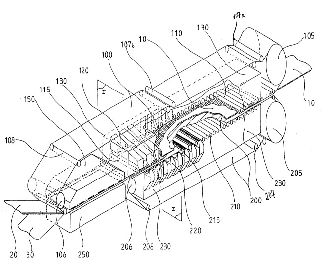
The assembling device includes three successive, though
considerably distinct, sections, ie,
- a first, so-called heating, section enabling the gelling
of the glue previously applied on the tips of the flutes
of the upper, so-called single-face layer 20 which is
destined to be assembled with the lower, so-called liner,
layer 30, the two webs 20, 30 being travelling through in
the form of webs;
- a second, so-called drying and pulling, section enabling
the extraction of the residual moisture of the two layers
20, 30, this section contributing also, .at least
partially, to the conveyance of the corrugated board 10
being produced, and
- a third, so-called driving and cooling, section acting on
the two assembled layers 20, 30, ie on the corrugated
board 10 being produced.
The first section consists essentially of a lower single
horizontal heating plate 250 situated underneath the track of
the webs 20, 30 and topped by an upper blowing case 150. The
heating plate 250 can be, a cast or steel case fed with steam.
Its crosswise dimension is slightly larger than the usable
width of the corrugator, its width being about 2m. To avoid
any deformation, the plate has inner reinforcement with the
forms of ribs or braces acting as protuberances which
increase the heat exchange between steam and case. The upper
surface of this plate is perfectly plane allowing to avoid
the accumulation of impurities likely to scratch the surface
of the outer liner. Machining and fitting of this single
heating plate are possible owing to its dimensions. The
purpose of the upper blowing case 150 is to blow air
- 2055403
- 8 - JBF102
downwards onto the upper side of the single face layer 20 in
order to fully flatten on the heating plate 250 the
corrugated board 10 being produced.
As shown by fig. 1, the heating section comprises a row of
upper identical nozzles 120 arranged crosswise, ie
perpendicularly to the travelling direction of the layers 20,
30, extending over at least the whole usable width of the
corrugator and arranged parallelly to one another and
sequentially in the running direction. Preferably, the
heating section should comprise a row of lower nozzles 220
symmetrically arranged in correspondence with the upper
nozzles 120. All the nozzles 120, 220 have a commpn oblique
parallelepipedic shape, which means that if the upper nozzles
120 are considered, they are higher in the lateral area from
which the air arrives. The lower base of the upper nozzles
120 has a truncated shape arranged downwards which, on
account of the ensuing decremental air blowing section, will
engender a slight speed increment of the outflowing air. The
upper nozzles 120 are located on an upper suction case 130
whereas the lower nozzles 220 are located on a lower case
230.
As may be gathered more easily from fig. 2, the hot and dry
air arrives from a duct 50 before being distributed through a
number of lower supply pipes 52 to the lower corresponding
nozzles 220, and by a number of upper supply pipes 54 to the
upper nozzles 120. The hot air is thus blown down against the
upper side of the single-face layer 20 and upward against the
lower side of the liner layer 30 before being sucked upward
by the upper case 130 and downward by the lower case 230. The
two cases 130, 230 are provided with the ducts 62 and 64
respectively connected to the outlet 60 towards a single pump
(not shown) engendering sufficient low pressure with the
cases.
- 2055403
_ g _ JBF102
If consideration is given to fig. 1, it will become obvious
that the upper case 130 extends towards the right-hand side,
ie upstream, beyond the row of upper nozzles 120, this
extension making thus up the upper part of the third,
so-called driving and cooling, section. Similarly, the lower
case 230 also extends towards the right-hand side beyond the
row of lower nozzles 220. The inner side of the straight
parts of the cases 130, 230 having also low pressure due to
the action of the outlet suction pump, fresh air will stream
through the horizontal slot subsisting at the level of the
board 10 between the two cases, before escaping through the
duct 60.
Referring once more to fig. 1, it may be noticed that the
conveyance of the webs 20, 30 and, hence, of the corrugated
board 10 being produced, is achieved by an upper belt 100 and
a lower belt 200 both moving endlessly and synchronously.
Considering an inlet drum 106 as a starting point situated
upstream the blowing case 150, the upper belt 100 will travel
firstly in between this blowing case 150 and the heating
plate 250, then into the second, so-called drying, section
topped by the upper nozzles 120, and also under the first
pressure rollers 115 each of them located between two upper
nozzles 120 arranged successively and parallelly to them. The
upper belt 100 then persues the travel into the third,
so-called driving and cooling, section topped by further
pressure rollers 110 parallel to one another and located side
by side in the travelling direction of the board 10
processed. All these rollers 110, 115 are arranged crosswise
to the corrugated board 10. At the outlet of the third
section, the upper belt 100 ascends and runs around a drum
105 in order to be taken over by a first upper stretching
roller pair 107a and to return to the inlet drum 106, the
2055403
- 10 - JBF102
said belt being supported by a second upper roller pair 107b
situated mainly in the center of the device as well as by an
upper guiding roller 108 situated mainly above the blowing
case lS0.
The lower belt 200 leaves an inlet drum 206 situated after
the heating plate 250 and penetrates direct into the second
section. At that stage, the belt 200 runs over the lower
nozzles 220 and also over the crosswise arranged supporting
rollers 215 which are parallel to one another and alternately
arranged each between two successive lower nozzles 220. This
belt 200 then pursues its way in the third, so-called driving
and cooling, section over a range of supporting r~ollers 210
situated opposite a range of pressure rollers 110 as
previously described. At the outlet of the assembling device,
the lower belt 200 descends and runs around the lower drive
drum 205 in order to be taken over by a pair of lower
tightening rollers 207 before being directed firstly towards
the rear of a lower guiding roller 208 and being returned to
the inlet roller 206.
In the course of a production run, the single-face layer 20
and the liner paper 30 supplied by a previous, so-called glue
unit, station run into jthe first section where the blowing
case 150 applies the layer 20 against the layer 30 and the
latter against the heating plate 250 causing the gelling and
setting of the glue.
The corrugated board 10 thus assembled but still wet is taken
in at the inlet of the second station between the upper belt
100 supported downwardly by the pressure rollers 115 and then
110, and the lower belt 200 held in place by the supporting
rollers 215 and, further on 210. Considering that the only
friction forces to be overcome are those generated in the
2055403
- 11 - JBF102
first heating section, the useful pulling track length
corresponding to the length of the upper side of the lower
belt 200 can be reduced to considerably lesser dimensions in
comparison to those currently used up to now.
As the belts 100, 200 have a meshed structure, the air blown
from the nozzles streams easily through. Thereby the air
stream gets loaded with humidity and is immediately absorbed
by the suction cases 130 and 230. Attention should be drawn
to the fact that the useful suction area at the level of the
corrugated board 10 comprises the spaces between the nozzles,
though without the visible section of the rollers 115, 215
which is aerodynamically rather insignificant.
Furthermore, the board 10 undergoing a drying process and
cooling down simultaneously in the third section is reliably
held flat between the two belts 100, 200 which are themselves
guided by the roller sets 110, 210.
Considering the high drying power ensured by the nozzles and
the suction cases, it might be appropriate to use only one
row of such nozzles, ie the upper ones or the lower ones.
Similarly, it is also envisageable to arrange a regulating
shutter at the inlet of 2ach of the nozzles so as to have the
possibility to use only part of the nozzles if required.
Numerous modifications can be added to the device described
above without impairing the essential idea of the invention.
So, for instance, the hot air used for heating and drying can
be substituted for by infra-red, ultra-violet and micro-wave
irradiations or electron-beam etc, combinations of the
various systems being equally possible. The heating systems
thus allows to also heat with a differential heat input
crosswise to the web in order to cope with possible
transverse moisture variations appearing in the form of
streaks in the travelling direction of the various layers.