Note: Descriptions are shown in the official language in which they were submitted.
. 1 .
T 6131 CA~.'J
Hsb
RECOVERING HYDROCARBONS FROM TAR SAND OR HEAVY OIL RESERVOIRS
The present invention relates to recovering hydrocarbons from
an underground tar sand reservoir or from a heavy oil reservoir.
Such a reservoir contains oil that is so viscous that the reservoir
may be initially impermeable. In order to produce hydrocarbons from
such a reservoir the viscosity of the oil has to be reduced, this
can be done by heating the reservoir.
Known is a method of recovering hydrocarbons from an under-
ground tar sand or heavy oil reservoir which comprises (a) drilling
and completing a pair of wells, which pair comprises an injection
well terminating in the reservoir and a production well terminating
in the reservoir below the injection well; and (b) creating a
permeable zone between the injection well and the production well.
After having created permeable zones between the injection well
and the production well steam injection through the production well
is stopped and steam is only injected through the injection well
while hydrocarbons are produced through the production well.
It is believed that the injected steam forms in the reservoir a
steam-containing, heated zone along the injection well and that
hydrocarbons are mobilized in the heated reservoir and drain
through the heated zone to the production well which is located
below the injection well. Therefore this method is referred to as
steam assisted gravity drainage.
It is an object of the present invention to improve the known
method.
To this end the method of recovering hydrocarbons from an
underground tar sand reservoir or heavy oil reservoir according to
the present invention comprises (a) drilling and completing at
least two pafrs of wells, Wherein each pair of wells comprises an
injection well terminating in the reservoir and a production well
terminating in the reservoir below the injection well, and wherein
°
~C3~9rv
1 z ~ ~<J ~ .l
- 2 ,
the second pair of wells faces the first pair of wells; (b) creat-
ing for each pair of wells a permeable zone between the injection
well and the production well; and (c) injecting steam through Che
injection wells while producing hydrocarbons through the production
wells, wherein the injection pressure of the injection well of the
first pair of wells is greater than the injection pressure of the
injection well of the second pair of wells.
The effect of injecting steam at different pressures is that
the steam-containing zone of the injection well pertaining to the
first pair off wells grows further into the reservoir away from the
injection well towards the injection well of the second pair of
wells.
The present invention will now be described in more detail with
reference to the accompanying drawings, wherein
Figure 1 shows schematically a perspective view of the under-
ground tar sand reservoir with two pairs of wells;
Figure 2 shows schematically a vertical cross-section of the
underground tar sand reservoir of Figure 1;
Figure 3 shows schematically a perspective view of the under-
ground tar sand reservoir with three pairs of wells; and
Figure 4 showing a plan of the surface locations of four rows
of wells.
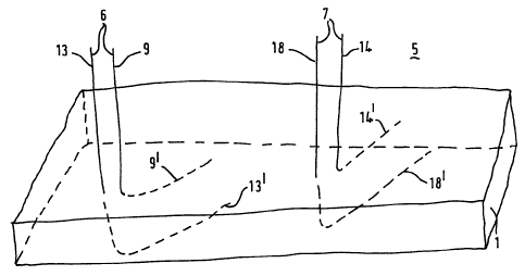
Reference is now made to Figure 1 showing an underground tar
sand reservoir 1 which reservoir is located below a covering
formation layer 5 which formation layer extends to surface (not
shown). From the surface to the reservoir two pairs of wells have
been drilled, a first pair 6 comprising wells 9 and 13 and a second
pair 7 comprising wells 14 and 18. Each pair 6 and 7 of wells com-
prises an injection well 9 and 14, respectively, which injection
wells terminate in the reservoir, and each pair 6 and 7 of wells
comprises a production well 13 and 18, respectively, which produc-
tion wells 13 and 18 terminate in the reservoir below the injection
well 9 and 14. The second pair 7 of wells faces the first pair 6 of
wells.
- 3
Each well has a horizontal end part that is located in the
underground tar sand reservoir 1, the horizontal end parts are
referred to with reference numerals 9', 13', 14' and 18'. Please
note that dashed line segments have been used to show the part of
the well that is below the top of the tar sand reservoir 1. Each of
the wells 9, 13, 14 and 18 has been completed with a casing (not
shown) which extend to total depth and which is perforated in the
horizontal end part 9', 13', 14' and 18', respectively. Furthermore
each of the wells 9, 13, 14 and 18 has been provided with a tubing
(not shown) extending into the horizontal end part 9', 13', 14' and
18', respectively.
During normal operation for each pair of wells a permeable zone
between the injection well 9 or 14, respectively and the production
well 13 or 18, respectively is created in the initially impermeable
tar sand reservoir 5. Creating the permeable zones comprises
circulating steam through the injection wells 9 and 14 and
performing alternate steam injection and hydrocarbon production
through the production wells 13 and 18. Circulating steam through a
well is done by injecting steam through the tubing arranged in the
well and producing fluids through the annulus between the tubing
and the well casing, or by injecting steam through the annulus and
producing fluids through the tubing. The alternate steam injection
and hydrocarbon production through the production wells 13 and 18
can be interrupted for a period in which the production wells 13
and l8 are closed in so that the production wells are operated
according to a steam soak method or a huff and puff method. Alter-
nate steam injection and hydrocarbon production through the pro-
duction well 13 can be done in phase with alternate steam injection
and hydrocarbon production through the production well 18, or it
can be done out of phase so that when injection is carried out
through production well 13 hydrocarbons are produced through well
18 followed by the reverse.
When a permeable path has been created between the injection
wells and the production wells, steam injection through the pro
duction wells 13 and l8 is stopped and steam assisted gravity
~~ 7~f3
- 4 -
drainage according to the present invention is started. To this end
steam is injected through the injection wells 9 and 14 ~>>hile
producing hydrocarbons through the production wells 13 and 18,
wherein the injection pressure of the injection well 9 of the first
pair 6 of wells is greater than the injection pressure of the
injection well 14 of the second pair of wells 7.
Reference is now made to Figure 2. During the steam assisted
gravity drainage according to the present invention steam enters
the formation through the horizontal parts 9' and 14' of the
injection wells, and steam-containing zones 20 and 21 are formed.
As a result of the difference in the injection pressure the steam-
containing zone 20 can expand and become larger than the steam-
containing zone 21. In this way a larger part of the reservoir is
heated than in the conventional method. Therefore in the method
according to the present invention a larger steam-containing zone
is created which results in a larger recovery rate and a higher
recovery efficiency. The improvements are shown in the following
hypothetical example.
A numerical simulation study has been carried out to compare
the present method with a base case. The reservoir conditions were
those of the Peace River tar sand reservoir in Canada. In the tar
sand reservoir having a formation thickness of 26 m at a depth of
about 570 m two pairs of wells were arranged, the length of the
horizontal wells was 790 m. The horizontal parts of the production
wells were about 10 m below the horizontal parts of the injection
wells. The horizontal spacing between the two pairs of wells was
64 m
The path was prepared as follows. At first steam is circulated
in the injection wells at 260 °C to heat the formation surrounding
the injection wells 9 and 14 and heated fluids are produced to
reduce the pressure increase in the reservoir. This continues for
one year. During this period production well 13 undergoes alternate
periods of steam injection and production. Thereafter steam having
a steam quality of 90~ (this is steam containing 10~ by mass of
water in the liquid phase) is injected through production well 13
N x~
!;
~e3~~~~~
_ 5 .
and fluids are produced through production well 18 for 60 days.
Thereafter the reverse is done for 60 days. This 120 days injection
and production cycle is repeated twice.
Thereafter steam assisted gravity drainage is started. For the
base case steam is injected through the injection wells 9 and 14
with injection pressures of 4 000 kPa and fluids are recovered
through the production wells 13 and 18. At the end of a ten year
period the recovery efficiency was 0.62, wherein the recovery
efficiency is the amount of recovered tar divided by the amount of
tar originally in place, and the cumulative oil production was
184 000 m3.
Steam assisted gravity drainage according to the present
invention is done after the path was prepared as described above by
injecting steam through the injection well 9 at a pressure of 4 000
kPa and through the injection well 14 at a lower pressure of 3 500
kPa. At the end of a ten year period the recovery efficiency was
0.90 and the cumulative oil production was 267 000 m3.
The difference in injection pressure between adjacent injection
wells is suitably between 50 and 2 000 kPa.
In the method discussed with reference of Figures 1 and 2 only
two pairs of wells were used. It will be appreciated that a further
pair of wells can be used as well as shown in Figure 3, the wells
of this further pair 24 are referred to with reference numerals 25
and 26. The injection well is well 25 and the production well is
wall 26. The further pair 24 of wells faces the second pair 7 of
wells.
The further pair 24 of wells is a first pair of wells with
respect to the second pair 7 of wells. So that during normal
operation after establishing a permeable zone between the injection
wells 9, 14 and 25 and the production wells 13, 18 and 26 as
described above the steam injection pressures in the injection
wells is so selected that the injection pressure in the injection
wells 9 and 25 is greater than the injection pressure in the
injection well 14. Suitably the pressure difference is between 50
and 2 000 kPa.
r r
~. t~~~ ~.,
e.~ e7 r~ ~~ r~
- 6 -
A next pair of wells (not shown) can be used as well right o.f
the further pair 24 of wells which is a second pair of wells with
respect to the further pair 24 0~ wells. When more pairs of wells
are used the designations first and second pair of wells follows
the above trend.
Reference is now made to Figure 4 showing the surface locations
of four rows of wells referred to with reference numerals 41, 42,
43 and 44. Row 41 comprises two pair of wells, each pair comprises
an injection well 46 and 49, respectively and a production well 48
and S3 respectively. Row 42 comprises two pair of wells, each pair
comprises an injection well 55 and 57, respectively and a produc-
tion well 56 and 59 respectively. Row 43 comprises two pair of
wells, each pair comprises an injection well 61 and 6S, respec-
tively and a production well 62 and 66 respectively. Row 44 com-
prises two pair of wells, each pair comprises an injection well 67
and 70, respectively and a production well 69 and 72 respectively.
The injection wells terminate in the reservoir (not shown) and the
production wells terminate in the reservoir below the injection
wells.
Row 42 of wells faces row 41 of wells, and row 42 is a second
row of wells with respect to row 41. Row 43, facing row 42, is a
first row o~ wells with respect to row 42, and row 44 is a second
raw of wells with respect to row 43.
During normal operation permeable zones are created between the
injection wells and the production wells, which comprises circu-
lating steam through the injection wells and performing alternate
steam injection and hydrocarbon production thxough the production
wells.
Thereafter steam is injected through the injection wells,
wherein the injection pressure of injection wells pertaining to the
first rows 41 and 43 of wells is greater than the injection pres-
sure of the injection wells of the second rows 42 and 44 of wells.
Suitably the difference in injection pressure between adjacent
injection wells is between 50 and 2 000 kPa.
~u1 r~xi~ .~:
_,_
Suitably the injection well and the production well of a pair
of wells have a horizontal end part (not shown) which is located in
the reservoir. The horizontal end parts can be parallel to each
other and the horizontal end part of production well extends in a
direction similar to the direction of the horizontal end part of
the injection well. Suitably the wells in a row of wells are so
arranged that the directions of the horizontal end parts of the
wells substantially coincide with the direction of the row.
The wells have been completed with a horizontal end part, and
the part of the casing in the horizontal end part is perforated. At
least part of the perforated casing can be replaced by a liner
arranged in the horizontal section of the borehole.
The wells can also be completed with more than one tubing, for
example a dual tubing completion so that injection is done through
one tubing and production through the other tubing instead of
through the annular space surrounding the tubing.