Note: Descriptions are shown in the official language in which they were submitted.
205~7~9
TITLE OF THE INVENTION
HIGH-POWER RADIATOR
~ACKGROUND OF THE INVENTION
Field of the Invention
The invention relates to a high-power radiator,
especially for ultraviolet light, having a discharge
~pace which is filled with a filling gas which emit~
radiation under discharge conditions, formed by the in-
ternal space of a cooled hollow body con~i~ting of amaterial which is transparent to the radiation
generated, with dielectric tubes which are spaced from
the inner walls of the hollow body and which are pro-
vided with cooling channels and into which inner
electrodes are embedded or inserted, with a high-
tension source to feed the discharge.
Accordingly, the invention refers to a state of
the art as is evident, for example, from the EP
application bearing the publication number 0,363,832.
Discussion of Backaround
The indu~trial application of photochemical
proce~e~ iB greatly dependent upon the availability of
~uitable W source~. The conventional W radiators give
low to medium W intensitie~ at a few discrete wave-
lengtha, such as, for example, the low-pressure mercury
lamp~ operating at 185 nm and especially at 254 nm.
Really high W power levels are achieved only from
high-pre~sure lamps (Xe, Hg), which then however di~-
tribute their radiation over a greater wavelengthrange. The new excimer lasers made available certain
new wavelength~ for photochemical basic experiments.
- However, at the present time they are only in excep-
tional cases suitable for an industrial process, for
reasons of cost.
A novel excimer radiator is de~cribed in the
initially mentioned EP patent application, or al~o in
the conference publication "Novel W and VUV Excimer
- 2 - 2 0 5 ~ 7 0 9
Radiators~ by U. Koqelschatz and B. Eliasson, dis-
tributed at the 10th lecture meeting of the German
Chemists As~ociation, Photochemistry Technical Group,
in Wurzburg (F~G) on November 18-20, 1987. This novel
type of radiator is based on the principle that it is
possible to generate excimer radiation even in silent
electrical discharges, a type of discharge which is
employed on an industrial scale in the production of
ozone. In the current filaments of this discharge,
which are present only for a short time (a few nano-
seconds) inert gas atoms are excited by electron
collision, which atom~ react further to form excited
molecular complexes (excimers). These excimers have a
life of only a few nanoseconds, and on breaking up give
off their binding energy in the form of radiation, the
wavelength range of which may be in the W A, W B, WC
and VUV or also in the visible spectral range, depend-
ing upon the composition of the filling gas.
In very recent times the search for such high-
power radiators has intensified, ~ince the particularproperties of the radiator have opened up many new
areas of application in chemical and physical process
technology, in the qraphics industry, for coatings etc.
In addition to an optimal design of the
radiator with regard to dielectric material, ~lit
width, pressure, temperature and composition of the gas
employed, the effective cooling of the radiator is also
of decisive importance with regard to its commercial
application. In the case of the known radiators, the
outer electrode which i~ at earth potential i~ regu-
larly cooled. An optional feature is also a cooling of
the inner electrode ~which is at high-tension
potential), in this connection it merely being stated
that a li~uid or gaseous coolant is passed through the
hollow inner electrode. On account of the potential
conditions, when liquid cooling is employed it is
necessary to use a coolant which exhibits a very low
conductance, e.g. fully demineralized water, or oil. In
20~5709
addition, the cooling of the inner electrode must take
place in a closed circuit, on economic grounds.
SUM~ARY OF THE INVENTION
Proceeding from the prior art, the object of
the invention is to provide a high-power radiator,
especially for W or VW light, which can be cooled in
a technically ~imple and economic manner.
In order to achieve thi~ object with a high-
power radiator of the initially mentioned type, it is
provided accoxding to the invention that the hollow
body is in thermal contact with a cooling body in which
cooling channel~ () are provided, which are connected
to the cooling channels of the dielectric tubes and
form a closed coolant circuit, and in that a cooling
liquid having a low electrical conductance can be
pa~sed through these cooling channels.
In thi~ manner, the cooling device which is in
any event necessary for the (outer) hollow body form~
the heat exchanger for the coolant circuit of the di-
electric tubes. The hollow body can be cooled by
conventional tap water. ThuY, there i~ a saving of
large quantities of co~tly ully demineralized or
distilled water, or the need for an additional
circulatory cooling system for the dielectric tubes is
eliminated.
The invention i~ explained in greater detail
hereinbelow with reference to illu~trative embodiments.
BRIEF DESCRIPTION OF TH~ DRAWIN~S
A more complete appreciation of the invention
and many of the attendant advantage~ thereof will be
readily obtained a~ the same becomes better under~tood
by reference to the following detailed description when
considered in connection with the accompanying draw-
ings, wherein:
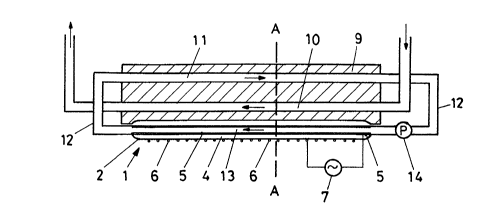
Fig. ~ show3 a longitudinal cro~s section through the
one W high-power radiator together with a
~ 4 ~ 2055709
diagrammatic representation of the two cooling
circuits;
Fig. 2 shows an enlarged and more detailed cros~-sec-
tional representation of the W high-power
radiator according to Fig. 1 along line AA
thereof in cross section, in this case the
cooling body additionally being employed as
carrier and cooler for the electrical feeding
of the radiator;
Fig. 3 shows an embodiment with a different type of
radiator;
Fig. 4 shows a cross section through the radiator
according to Fig. 3 along line BB thereof;
Fig. 5 shows a longitudinal cross section through the
one W high-power radiator in a diagrammatic
repreæentation with cooling circuits for the
radiator and the high-tension ~ource.
DESCRIPTION OF TH~ PREFERR~D EMBODIMENTS
Referring now to the drawings, wherein like
reference numerals designate identical or corresponding
parts througho~t the several views, in Figs. 1 and 2
the high-power radiator consists, in the case of the
present example, of four cylindrical individual
radiators 1, the construction of which i~ known per se.
A dielectric tube 3 is disposed in an outer quartz tube
2, spaced from the latter. The annular space between
the two tubes forms the discharge space 4 of the
radiator. The inner wall of the dielectric tube 3 is
provided with a metal coating 5 (shown in Fig. 2 with
an exaggerated thickness), which forms the inner
electrode of the radiator. Alternatively, it is also
possible to use in place of a metal coating 5, metal
tubes which are covered with a dielectric coating, e.g.
ceramic-based. The outer electrode of the radiator con-
si~t~ of a wire grid or a wire gauze 6, which extends
over the entire length and a major part of the outer
periphery of the outer quartz tube 2. A high-ten~ion
, _ 5 _ 20~5709
source 7 to feed the discharge is connected to this
outer electrode and the inner electrode (Fig. 1).
The interior of the quartz tube 1 is filled
with a filling gas which emits radiation under dis-
charge conditions, e.g. mercury, inert gas, an inertgas/metal vapor mixture, an inert gas/halogen mixture,
possibly with the use of an additional further inert
gas, preferably Ar, He or Ne, as buffer gas.
As is evident from the enlarged cross-sectional
view according to Fig. 2, the four individual radiators
1 are situated in grooves 8 on the broad side of a
cooling body 9 consisting of material of good thermal
conductivity. These grooves 8 are matched in cross
section to the outer contour of the outer quartz tube
2. The cooling body 9 is provided with two groups of
cooling channels 10 and 11, which extend in the longi-
tudinal direction of the grooves. The cooling channels
10 of the first group lead to an outer cooling circuit
(not shown in any further detail). In the simplest
case, conventional tap water flows through them in the
direction of the arrow. The cooling channels 11 of the
other group are connected via connecting lines 12 and
suitable connection fittings (not shown) to the
internal ~pace 13 of the dielectric tubes 3. A pump 14
provides the circulation of a cooling liquid with low
electrical conductivity, e.g. demineralized water or
oil, in the cooling circuit which has ju~t been
described. In this manner, the cooling body 9 acts as
heat exchanger between the primary cooling system
tcooling channels 10) and the secondary cooling system
(cooliny channels 11, connecting lines 12, internal
space 13 of the dielectric tubes 3, pump 14). The
potential separation is ensured by the cooling liquid
in the ~econdary cooling system, which liquid has
virtually zero electrical conductivity.
In principle, the high-tension source 7
corresponds to those of the type employed to feed ozone
gener~tor~. Typically, it delivers an adjustable
20~s7as
-- 6 --
alternating voltage in the order of magnitude of
several hundred volts to 20,000 volts at frequencies in
the range of industrial alternating current up to a few
MHz, depending upon the electrode geometry, the pres-
sure in the discharge space and the composition of thefilling gas. In the UV high-power radiators under dis-
cussion here, the frequencies of the supply voltage are
as a rule considerably above industrial alternating
voltage; they may reach several hundred kilohertz. A
high-tension source 7 suitable for this purpose is as a
rule constructed in accordance with the principle of a
combinatorial circuit component and accordingly in-
cludes electrical and electronic components which must
be cooled and accordingly are mounted on profiled cool-
ing sections. According to a further development of theinvention, it is now provided that the cooling body 9,
which i9 in any event necessary for the cooling of the
radiator, is also utilized for the cooling of the com-
ponents of the high-tension source 7. Thi~ is illu~-
trated in Fig. 2 in that the profiled cooling sections15 of the high-ten~ion source 7 are secured directly on
the underside of the cooling body 9 of the radiator. In
thi~ manner, the fan in the high-tension source 7 can
be ~i~pensed with. As a result of the spatial proximity
of source and load, the cost of the electromagnetic
screening i~ lower. The construction of the entire
irradiation device may be designed on an extremely
modular ba~is.
In addition to the above described individual
radiators having a cylindrical cross section, it i8 of
course possible also to provide surface radiators, e.g.
according to EP-A-0,254,111, with a primary and a
secondary cooling circuit. Furthermore, W high-power
radiator~ having an entirely different geometry may be
equipped with the cooling concept according to the
invention. This is explained in greater detail herein
below with reference to Fig. 3.
_ 7 _ 2~5709
In this W high-power radiator, five dielectric
tubes 26 with hollow inner electrodes 27 are disposed
in a quartz tube 21 with a rectangular cross section
having the broad sides 22, 23 and the narrow sides 24,
25. The dielectric tubes 26 are spaced from one another
and also from the walls of the quartz tube 21. The di-
electric tubes 26 are, for example, small quartz tubes,
and the inner electrodes 27 are small metal tubes.
Instead of this, it is also possible to use a metal
tube encased with dielectric material.
The two narrow sides 24, 25 and one of the
broad sides 23 of the quartz tube 21 are each
externally provided with an aluminum coating 28. The
three coatings may, but need not, be electrically insu-
lated from one another. The aluminum coating 28 ispreferably vaporized, flame-sprayed, plasma-sprayed or
sputtered, and ~erves as reflector. The aluminum coat-
ings 28 on the narrow sides 24, 25 of the quartz tube
21 may moreover serve as additional outer electrodes
for a supply using a high-ten~ion source 7 having an
output which is ground-symmetric.
As may be seen from Fig. 4, the quartz tube 21
i8 sealed at its two end faces by plates 30, 31 con-
sisting of insulating material. These plates are, for
example, adhesively bonded onto the end faces or, in
the case of quartz or glass plates, melted together
with said end faces. The plates 30, 31 are provided
with pas~age~ 32 into which the dielectric tubes 26 are
in~erted and secured and sealed therein. Via a filling
connection 34, it is pos~ible to evacuate the internal
space of the quartz tube 1 and then to fill that space
with a filling gas.
A~ may be seen from Fig. 4, the electrical
~upply to the radiator is provided from a source server
of alternating voltage 7 in ~uch a manner that adjacent
inner electrodes (small metal tubes 27) are alternately
connected to the source server of alternating voltage
7. When a voltage is present, a multiplicity of
- 8 - 2~55709
discharge channels 19 are formed between adjacent
dielectric tubes 26, which give off the W light, which
then penetrate~ to the outside through the transparent
broad side 22 of the quartz tube 21. The proposed
supply permits the use of a high-tension source 7
having an output which is ground-symmetric. The cooling
body 9a can then be set to earth potential.
In order to provide the external cooling of the
radiator, the quartz tube 21 is inserted into a cooling
body 9a having a U-shaped cross section. Lateral
braided bands 18 provide the electrical contact between
the aluminum coating 28 and the limbs of the cooling
body 9a. An optional thermally conductive paste 29
between the lower broad side 23 of the quartz tube 21
is employed to improve the transfer of heat. In the
base portion of the cooling body 9a, a multiplicity of
cooling channels 10, 11 are provided, extending in the
longitudinal direction of the cooling body. The one
group, which i8 designated by 10, is employed, in a
manner similar to the embodiment according to Figs. 1
and 2 as the primary cooling circuit and, for example,
conventional tap water flows through this. The other
group, which i~ designated by 11, i~ connected to all
~mall metal tube~ 27, which are hydraulically connected
in ~eries or in parallel, via ~uitable connecting lines
12a and connection fitting~ (not shown). The pump 14
provides the circulation of a cooling liquid having a
very low electrical conductance in this secondary cool-
ing circuit. In this case, the cooling body 9a is
employed as heat exchanger between the two coolant
circuits.
In the illustrative embodiments described
- herein above, two group~ of cooling channels 10, 11
were provided in each case in the cooling body of the
radiator. It is, of course, within the scope of the
invention al~o to design the primary cooling circuit in
a different manner. Thus, for example, the cooling body
may dip partially into a coolant or may be provided
20~709
g
with large-area cooling fins, even subjected to forced
cooling with air. In the case of such alternatives,
there is no need for any alteration of the secondary
cooling circuit for the radiator.
A further alternative is diagrammatically
represented in Fig. 5. In this case, the cooling body 9
is employed both as heat exchanger for the internal
cooling of the radiator and also as heat exchanger for
a further cooling circuit to cool the high-tension
source 7. For this purpose, additional channels lla are
provided in the cooling body 9, which additional
channels are connected to cooling channels 33 in the
high-tension source 7 via connecting lines 12b and a
further pump 14a.
Obviously, numerous modifications and varia-
tions of the present invention are possible in light of
the above teachings. It is therefore to be understood
that within the scope of the appended claims, the
invention may be practiced otherwi~e than as
specifically described herein.