Note: Descriptions are shown in the official language in which they were submitted.
ND-8887
1 i~eC~Jt.. J~~~4
COOLING SYSTEM FOR A WATER COOLED INTERNAL COMBUSTION
ENGINE fOR VEHICLE HAVING AN AIR CONDITIONING APPAF,ATUS
BACKGROUND OF THE INVENTION
1. Field of the Invention
The present invention relates to an air
conditioning apparatus for a vehicle, capable of
obtaining a desired control of an engine cooling system
while obtaining a desired control of the air conditioning
apparatus.
2. Description of Related Art
In a vehicle provided with an internal
combustion engine, a radiator located in an engine
cooling water recirculating system is arranged at the
front of the engine body, and a cooling fan is arranged
on the rear side of the radiator. A flow of air induced
not only by the movement of the vehicle but also by the
rotation of the cooling fan passing through the radiator,
which can improve a heat exchange occurring at the
radiator. Furthermore, when the vehicle is provided with
an air conditioning apparatus, a condenser for condEnsing
the cooling medium.is arranged in front of the radiator
in the direction of the flow of the air. Therefore, the
flow of the air first passes through the condenser, and
is, then, directed to the radiator located downstream
from the radiator. When the air conditioning apparatus
is operating, a gas state cooling medium of high
temperature, owing to the compression thereof by a
compressor, is introduced into the condenser, and is
subjected to a heat exchange operation with respect to
the air flow, which causes the cooling medium to be
condensed to a liquid. Therefore, heating of the air
flow induced by the movement of the vehicle and by the
rotation of the cooling fan i.s generated when the air
flow is in contact with the condenser through which a
cooling medium of high temperature is passed, and the
- 2 -
heated air f7.ow is directed to the radiator located
downstream from the radiator in the direction of the flow
of the air. At the radiator, a cooling of the
recirculated engine cooling water takes place -to obtain a
desired temperature of the cooling medium.
It has recently been required that the air
conditioning apparatus for a vehicle be much more
comfortable, which necessarily increases the required
cooling ability of the air conditioning apparatus for a
vehicle. Furthermore, a recent preference for high power
engines has resulted in an increase in the amount of heat
generated from an engine. Recent requirements of luxury
cars has also resulted in the increase in the number of
parts in the engine compartment resulting in the
existence of Very little excess space in the same.
Furthermore, a declivity in of the hood is recently
preferred in car design, which decreases the air
generating efficiency induced by the movement of the car,
resulting in a reduction in the available amount of
cooling air.
When a loaded vehicle is climbing a slope in
high temperatures summer it cannot be expected to obtain
a high speed air fJ,ow induced by the movement of the
engine, and the engine generates and emits a very large
amount of heat, and the cooling demand, as required from
the air conditioning apparatus, is high. In this
situation, a large increase in the temperature of the air
directed to the radiator portion occurs, thereby reduces
the cooling ability of the cooling water in the radiator,
and resulting in an increase in the temperature of the
engine cooling water in the radiator.
In order to overcome the above mentioned
difficulty, a solution has been proposed that stops the
operation of the air conditioning apparatus when the
temperature of the cooling medium exceeds a temperature
of, for example, 100 degrees centigrade, or that uses a
larger sized radiator or cooling fan device.
- 3 -
ics~ '~.J~' 'J~~~~
However, forced cessation of t;he air
conditioning apparatus inevitably makes the cabin of the
vehicle less comfortable. Employing a larger sized
radiator fan is difficult to realize because of the
limited available space in the engine compartment of the
vehicle. In addition, employment of a larger sized fan
does not necessarily increase the amount of air flow
expected from the increase in the driving power owing to
the fact that the air flow resistance of a vehicle as a
total is increased.
Furthermore, when the engine is idling and
therefore cannot expect to obtain an air flow caused by
the movement of the vehicle, the amount of cooling air
introduced into the condenser is small, thereby causing a
reduction in the heat radiation efficiency of the
condenser, which causes an increase in the pressure of
the coolant issued .from the compressor. As a result, the
power necessary for driving the compressor is increased,
thereby reducing the fuel consumption efficiency during
the operation of the vehicle in high temperatures.
SUMMARY OF THE INVENTION
The present invention aims to overcome the above
mentioned difficulties encountered in the prior arts.
Therefore, an object of the present invention is to
provide an air conditioning apparatus, for an automobile,
capable of increasing its cooling ability.
Another object of the present invention is to
provide an air conditioning apparatus for an automobile,
capable of decreasing the driving power required for its
compressor to increase the fuel consumption efficiency of
an internal combustion engine.
Another object of the present invention is to
provide an air conditioning apparatus for an automobile
with a water cooled internal combustion engine, capable
of preventing an increase in the temperature of the
cooling medium for the air conditioner even when the
engine overheats because of an increase in the
- 4 -
temperature of the engine cooling water, and thereby
maintain a comfortable environment in the cabin of the
vehicle.
Still another object of the present invention is to
provide an air conditioning apparatus for an automobile
with a water cooled internal combustion engine, capable
of obtaining an effective operation even during high
temperatures in hot summer season.
In a vehicle with an internal combustion engine
having an engine body and a radiator located at the front
of the engine in the direction of the forward movement of
the vehicle, and an air-conditioning system having a
condenser arranged in front of the radiator the
improvement according to the present invention comprises:
means for allowing a flow of air to be
generated when the vehicle moves forward;
guide wall means for defining a first
passageway for receiving said flow as generated and
for obtaining a first flow of air from the condenser
to the radiator, said guide wall means preventing
the air, after passing through the radiator, from
being returned back around the radiator into the
flow from the,condenser to the radiator;
means for defining at least one second
passageway for receiving said flow as generated and
for obtaining an air flow by-passing the condenser
and directly introducing the by-passed air flow into
the radiator, and;
means, responding to a thermal load condition
of the engine, for selectively opening or closing
said second passageway.
BRIEF DESCRIPTION OF ATTACHED DRAWINGS
Fig. 1 is a schematic view of an arrangement in an
engine compartment in a prior art.
Fig. 2 is a schematic view of the arrangement in an
engine compartment according an embodiment of the present
invention.
- 5 - ~~SS~f;~
Fig. 3 is a schematic construction of an engine
water_ cooling system of an intE>rnal combustion engine for
a vehicle and air conditioning system.
Fig. 4 is a flow chart illustrating an operation of
the first embodiment.
Fig. 5 is an enlarged view illustrating a detailed
construction of first and second dampers in a second
embodiment.
Fig. 6 is perspective view of another embodiment of
the present invention.
Fig. 7 is a schematic view of still another
embodiment of the present invention.
Fig. 8 is a flow chart illustrating another example
of the operation of the present invention.
Fig. 9 is a schematic view of the arrangement in an
engine compartment according to one embodiment of the
present invention, wherein a concaved shape of the
condenser is employed.
Fig. 10 is an enlarged view illustrating detailed
dimensions of the condenser in Fig. 9.
Fig. 11 is similar to Fig. 9, but the condenser has
a convexed shape.
Fig. 12 is a modification of the embodiment in
Fig. 10 where each is made of small dampers.
Fig. 13 shows the dampers in Fig. 12 when open.
Fig. 14 is a schematic view of the arrangement in an
engine compartment according to an embodiment o~ the
present invention, where, in place of the second damper,
a fixed plate is employed.
Fig. 15 shows a perspective view of the embodiment
in Fig. 14.
Fig. 16 shows a perspective view of a duct alone in
Fig. 14.
Fig. 17 shows an upper view of an engine compartment
according to another embodiment of the present invention.
Fig. 18 is an enlarged, detailed view of a part of
the embodiment in Fig. 17.
- 6 ~ ~C'S~96
Fig. 19 show a cross secta_onal view of a fixed plate
in a modification.
Figs. 20 and 21 are similar to Fig. 19, but show
other modifications, respectively.
DESCRIPTION OF PREFERRED EMBODIMENT
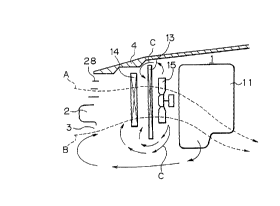
Fig. 1 generally illustrates a problem to be solved
by the present invention in the prior art. In Fig. l, a
reference numeral 11 denotes a body of an internal
combustion engine arranged in the engine compartment 1 of
an automobile. A reference numeral 4 is an engine hood,
28 a front grill, and 2 a bumper located below the front
grill 28 at the front side of the vehicle body. A
radiator 13 is arranged at the front of the engine
body 11. A gap 3 is formed below the bumper 2 on the
front side of the vehicle body. A condenser 14 for an
air conditioning apparatus is arranged in front of the
.radiator 13. The condenser 14 is for condensing the
cooling medium recirculated in the air conditioning
apparatus. Due to the movement of the vehicle on one
hand and the rotation of the fan 15 on the other hand,
flows A and B are created and directed, via the
condenser 14, to the radiator 13. The first flow A is
introduced into the engine compartment 1 via the front
grill portion 28, while the flow B is introduced into the
engine compartment via the gap 3 below the bumper 2.
According to the aerodynamic analysis by the inventors of
the present invention, it is found that a part of the air
after being subjected to the heat exchange at the
radiator 13 returns around the condenser 14 and/or the
radiator 13 as shown by arrows C, which are again
introduced into the radiator 13 or the condenser 14. As
a result of such a go back flow around the radiator 13 or
the condenser 14, a substantial reduction in the ability
to cool the engine cooling water occurs. In order to
solve this problem an aerodynamic analysis of the air
flow passing through the vehicle is carried out by the
inventors of the present invention. First, the
' - '~'(?a;a9fi4
observation of an air .flow in the engine compartment 1 of
the vehicle by the inventors affirmed that, after the air
flow is initially in contact with the radiator 13 for
subjecting it to the heat exchange operation therewith, a
partial return flow is created around the radiator or
condenser. It is presumed that all of the air flow
induced by the movement of the vehicle or the .rotation of
the cooling fan 15 passes through the radiator 13 to
contact thereby, but, because of the existence of a
reverse flow, the amount of air flow passing through the
condenser 14 is substantially smaller than the amount of
air passing through the radiator 13. In order to affirm
this prediction, hot wire type air flow speed meters are
arranged in front of the radiator 13 and condenser 14 to
detect the actual air flow values. As a result of this
measurement, the inventors of this invention found that,
under idling conditions, there is a 35 percent decrease
in the amount of air flow passing through the
condenser 14, after passing through the radiator. The
fact that there is a decrease in the amount of air flow
passing through the condenser after passing through the
radiator is justified if the vehicle is climbing a slope,
however, it was also found that the greater the speed of
the vehicle, the smaller the decrease in said amount of
air flow. Such a decrease in the amount of air flow in
contact with the condenser 14 can necessarily greatly
increase the temperature of the air after contacting the
condenser 14, which is, as previously mentioned, partly
returned to the radiator due to the reverse flow
generated in the engine compartment, which greatly
increases the temperature of the air at the inlet of_ the
radiator 13, thereby resulting in the reduced cooling
efficiency of the coolant in the radiator.
Fig. 2 illustrates an embodiment of the present
invention that can overcome the above mentioned
difficulty in the prior art. An explanation of a
construction similar to that of the prior art in Fig. 1
__ g _
i~~'~~~5~
is omitted to eliminate unnecessary repetition of the
explanation, while the same reference numbers are used
for the parts as in Fig. 1. A tubular duct 21 of
rectangular cross sectional shape is arranged between the
condenser 14 and radiator 13 for obtaining a controlled
flow of cooling air from the condenser 14 to the
radiator 13. The duct 21 also serves to prevent hot air
from the engine 11 from returning to the cooling air
passageway between the condenser 14 and the radiator 13.
The guide duct 21 is provided with a first damper 220
arranged at the bottom thereof for selectively creating a
passageway 15 for by-passing the radiator 13, and the
guide duct 21 is also provided with a second damper 221
arid guide 222, for dividing the cooling air passageway
between the condenser 14 and the radiator 13 into two
sections, as will be described later. The first
damper 220 is, at its bottom end, pivotally connected to
the bottom end of the radiator 13, so that the other end
(upstream end) of the first damper 220 is moved between
an opened position shown by a solid line, where the
damper 220 is spaced from the condenser 14 to form the
by-pass passageway 15, and a closed position shown by a
dotted line where the damper 220 is in contact with the
condenser 14. An actuator 25 is provided for obtaining a
pivotal movement of the first damper 220 for carrying out
the selective by-pass operation.
The second damper 221 is, at its first end (upstream
end), pivotally connected to the bottom end of the
condenser 14, so that the other end (downstream end) of
the damper 221 is moved between a non-partitioning
position where the damper 221 is in face to face contact
with the first damper 220, which is closed as shown by
the dotted line, and a partitioning position as shown by
the solid line where the by-pass passageway 15 of air
into the radiator 13 from the outside of the duct 21 for
direct introduction of the said air, is created.
The guide 222 has, at its center position 222a, a
- 9 - ~C~~J~f 4
pivot axis, so that the guide 222 is moved between a
partitioning or inclined position, as shown by the solid
line where the guide 222 is situated as an extension of
the second guide 221 for creating the direct flow of air
into the radiator 13 via the by-pass passageway 15, and a
non-partitioning or horizontal position, as shown by a
dotted line where the guide 222 is located parallel to
the flow of the cooling air from the condenser 14.
These dampers 220, 221 and 222 are controlled in
accordance with the thermal load of the engine 11
detected, for example, by the temperature of the cooling
water of the engine. Namely, when the first damper 220
is closed (dotted line), the second damper 221 is in face
to face contact with the first damper 220 and the
guide 222 is in a horizontal position (dotted line), so
that all of the air from the condenser 14 is introduced
into the radiator 13, as shown by an arrow A in Fig. 1,
mainly from the front grill 28, i.e., no air flow by-
passing operation is obtained. The air flow after
contacting the radiator 13 is directed to the engine body
via the fan 15 located inside a duct 15a, and leaves the
vehicle. Contrary to this, when the first damper 220 is
opened (solid line.in Fig. 1), the second damper 221 and
the guide are rotated to the respective partitioning
positions (solid line), so that the flow, as shown by the
arrow A from the radiator 14, and also the direct flow
by-passing the condenser 14, as shown by an arrow B from
the gap 3 below the bumper 2, are directed to the
radiator 13.
Fig. 3 generally shows a recirculation system of the
engine cooling water as well as an air conditioning
apparatus for the vehicle. The recirculation system for
the engine cooling water includes a water pump 12, which
supplies the cooling water via the radiator 13 to a water
jacket in the engine body 11, from which the cooling
water is removed by a water pump 12 for recirculation.
An engine cooling water temperature sensor 27 is arranged
l0 _ ~('~~~~i~
in the recirculating pipe line at a position upstream of
the engine body 11 for cooling water temperature Tw
detection.
The air conditioning system includes, in addition to
the previously mentioned condenser 14, a compressor 16, a
receiver 17, an expansion valve 18 and an evaporator 19.
As is well known, the gaseous cooling medium of high
temperature and high pressure from the compressor 16 is
introduced into the condenser 14 to liquidize the coolant
thereat. The thus obtained liquid coolant is introduced,
via the receiver 17 and the expansion valve 18, to the
evaporator 19 whereat a heat exchange operation takes
place to cool the air flow in contact with the
evaporator 19, the air flow of which is introduced into
the passenger room for air conditioning thereof. The
coolant after subjected to the heat exchange operation at
the evaporator 19 is returned to the compressor 16 for
repetition of the cooling cycle of the cooling medium for
air conditioning. As is well known to those skilled in
this art, a control apparatus for controlling the degree
of opening of the expansion valve 18 is provided in
accordance with the change in the pressure inside the
temperature sensitive tube 20 at the outlet of the
evaporator 19, the pressure of which corresponds to the
temperature of the cooling medium at the outlet.
As shown in Fig. 3, a spring 23 is connected to the
first damper 220 for urging it to normally take the
closed position. The actuator 25 connected to the first
damper 220 is constructed as a vacuum actuator having a
diaphragm {not shown) therein to which a three way
valve 24 is connected. The valve 24 is switched between
a first position where the vacuum actuator 25 is
connected-to a pipe 24-1 opened to the atmospheric
pressure and a second position where the actuator 25 is
connected to a pipe 24-2 opened to a vacuum source such
as an intake manifold (not shown) of the engine 11 or
vacuum pump (not shown). When the three way valve 24 is
- 11 - ~C~S'~s4
located so that the vacuum actuator 25 is opened to the
vacuum source, the actuator 25 generates a force against
the spring 23 to open the first damper 220. The
actuator 25 also serves to operate the second damper 221
and the guide 222, for which a link mechanism (not shown)
is arranged between the actuator 25, the damper 221 and
guide 222, thereby obtaining a cooperative movement of
the second damper 221 and guide 222 with respect to the
first damper 220, as already explained.
A control circuit 26 as a microcomputer unit is
provided for controlling the electric operated fan 15,
the electromagnetic three way valve 24, the
compressor 16, a fan (not shown) for directing flow of
air to the evaporator 19, and a damper (not shown) for
controlling flow to the evaporator 19. z'he control
circuit 26 is connected to various sensors for receiving
various electric signals, such as an engine speed signal
Ne, an engine cooling water temperature signal from the
sensor 27, a signal from a sensor 29 indicating the
temperature of the air to be cooled by the evaporator 19,
and a signal form the sensor 28 for detecting the
pressure of the cooling medium for the air conditioning
apparatus. .
Now, an operation of the air conditioning apparatus
according to the present invention will be described with
reference to a flow chart shown in Fig. 4. The routine
in Fig. 4 is commenced when the engine is started
(step 200). At step 201, the electromagnetic three way
valve 24 is operated so that the actuator 25 encourages
the first damper 220 to take a closed position as shown
by the dotted line in Fig. 2, while the second damper 221
is brought in face to face contact with the first
damper 220 located as shown by the dotted line, and the
guide 220 is brought to a position, as shown by the
dotted line, which is parallel to the flow of the air in
the duct 21, so as not to provide any flow resistance to
the flow from the condenser 14 to the radiator 13. As a
- 12 -
esi~a~.J'r9~
result, all of the air flow directed to the radiator 13,
as shown by an arrow A, and because of the movement of
the vehicle and the rotation of the fan 15, is coming
from the condenser 14 (see step 202). As will be
understood from the above, according to this usual mode
of operation including an engine idling operation,
because of the closed position of the damper 220, which
prevents air flow being directly introduced into the
radiator 13 by by-passing the condenser 14, a substantial
increase of the cool air flow amount passing through the
condenser 14 (up to 30 percent) can be obtained in
comparison with the prior art apparatus (Fig. 1) during
the idling operation. The increase of the cooled air
amount to the condenser 14 can increase the heat emission
ability by the condenser 14 itself when the air
conditioning apparatus is operated under engine idling
conditions even during high temperature which enhances
the air conditioning efficiency of the passenger cabin
while decreasing the pressure of the cooling medium at
the outlet of the compressor 16, thereby decreasing the
consumption of engine power by the compressor 16.
According to the result of the test done by the
inventors, a 5 percent increase in the cooling ability is
obtained over the prior art under engine idling
conditions during high temperatures and a 9 percent
decrease in the power required for driving the compressor
is obtained.
Furthermore, the increased amount passing through
the condenser 14 also reduces the increase in the air
flow temperature after contacting the condenser 14,
thereby a reducing the temperature of the air introduced
into the radiator 13. As a result, the engine cooling
water can maintain a lower temperature -than that in the
prior art.
During the execution of the routing in Fig. 4, the
temperature TW of the engine cooling water is detected by
- 13 -
~(' r59fi~
the temperature sensor 27 (step 203), and determined if
the detected value of the TW i.s equal to or larger than a
predetermined value, such as 100 degrees centigrade
(step 204). So long as it is detected that < 100 ° (No
result at step 204), the routine for the usual mode, as
described above, is repeated to maintain the first
damper 220 in a closed position while the second
damper 221 and 'the guide 222 axe rendered in-operative.
When a vehicle is operating under high load
conditions, such as climbing a steep slope with low
vehicle velocity, the engine cooling water temperature TW
can reach 100°C (result at step 204), so that the control
circuit 26 issues a signal to the three way switching
valve 24 to cause the diaphragm mechanism 25 to move the
first damper 220 against the spring 23 to an open
condition as shown as a solid line in Fig. 2, while the
second damper 221 and guide 222 are moved to their
respective partitioning positions (solid line). As a
result, in addition to flow A of the air directed to the
radiator 13 via the condenser 14, a flow, as shown by B
by-passing the condenser and being directly introduced
into the radiator 13, is obtained via the by-pass
passageway 15. This means that, in this operation mode,
the total air flow passing through the radiator is a sum
of flow A from the condenser 14 and by-pass flow B of a
temperature lower than that of the first flow A. As a
result, an increase in the amount of cooling air is
obtained by this mode in comparison with the usual mode
obtained by a closed position (solid line) of the first
damper 220 wherein only flow A is obtained. As a result,
an increase in the cooling ability at the radiator 13 can
be obtained.
There is, of course, a decrease in the amount of the
cooling air passing through the condenser 14, as shown by
an arrow A at this second mode when compared with that
obtained at the first, usual mode, wherein the first
14 - I~r~a~'~J~~3~
damper 220 is closed, resulting in an increase in the
temperature of the air conditioner cooling medium across
the condenser 14. However, irrespective of this increase
in the temperature across the condenser 14, a mean
temperature of the air introduced into the radiator 13
is, as a total, reduced in comparison with when the first
damper 220 is closed, because the air flow B introduced
into the radiator 13 flowing along the direction of the
movement of the vehicle has a lower temperature
substantially corresponding to atmospheric temperature,
which becomes the temperature at the inlet of the
radiator 13. As a result, a large amount of heat
emission is obtained at the radiator 13, permitting the
reducting of the temperature of the engine cooling water.
According to the result of the test by the inventors, an
increase of about 10 percent in the cooling ability is
obtained in a 2000 cc engine.
The area SBOf the front side of the radiator 13,
which flow B of the cooling air is in contact with (the
area of the passage of the cooling air flow defined below
the line of intersection of the plane defined by the
second damper 221 and the guide 222 with the radiator 13)
is preferably smaller than the 40~ of the total front
area S of the radiator. This preferable relationship
between SB and S is determined by the mutual positional
relationship between the condenser 14 and the
radiator 13, as well as by the shape of the front end of
the vehicle body. Namely, the greater the area of the
passageway to the radiator 13 to which the air flow B is
directed, the smaller the amount of air flow A contacting
the condenser 14. When the vehicle is climbing a slope
at a low speed, the engine speed is high, so that a large
amount of air conditioning cooling medium is forced out
of the compressor 16, therehby increasing the cooling
ability of the air conditioning system. However, a
reduction in the amount of air flow A contacting the
- 15 - ~C'~59~4
condenser can increase the power consumption for driving
the compressor 16. This means that the ratio of areas
between SB and S should be determined so that the above
mentioned advantage obtained by an increase in the area
for air flow B is harmonized with the above mentioned
disadvantage obtained by the reduction in -the amount of
air flow A. According to this embodiment, the ratio of
value, in percent, of the inlet area SB of the
radiator 13 for flow B to the total inlet area S of the
radiator 13 is about 40 percent when the amount of air
flow A passing through the condenser 14 is maintained at
the value of air .flow passing through the condenser 14 in
the prior art device shown in Fig. 2. This clearly shows
that the present invention makes it possible to obtain a
reduced temperature of the engine cooling water without
reducing the air conditioning ability of the air
conditioning apparatus.
In a preferable embodiment, the engine cooling water
from the engine 11 is introduced into the radiator from a
bottom tank, then into a core portion with which air
flow A or B is in contact, and finally into an upper tank
from which the cooling water is returned to the engine.
From the view point. of increasing the efficiency of the
emission of the heat from the radiator 13, it is
desirable to introduce air flow B at the bottom of the
radiator 13, i.e., the lower portion of the radiator
core.
As mentioned above, in the above embodiment, during
the usual mode of the operation, a main consideration is
an increase in 'the efficiency of the air conditioning
apparatus, and for realizing it, dampers 220 and 221 are
closed to increase the amount of air introduced into the
condenser 14, so that an increase in the air conditioning
ability can be obtained, while an increase in fuel
consumption efficiency can be obtained at the same time
because of the effective use of the flow of the cooling
2(.'~~5~6~
- 16 -
air. Contrary to this, when operating under sever
conditions, such as climbing a steep slops in high
temperatures infrequently the dampers 220 and 221 are
opened after a predetermined temperature (100 degrees
centigrade) of the engine cooling water is obtained, for
increasing the cooling ability of the radiator 13.
Fig. 5 is a second embodiment of the present
invention, wherein a first and second damper 220 and 221
are constructed by a plurality of small dampers 220a and
221b, respectively. Each of the small dampers 220a has a
pivot shaft 220a-1 for rotating it about its axis. The
pivot shaft 220a-1 is connected to one end of a
respective arm 220a-2, and the other end of the arm 220a-
2 is connected, via a common rink 225 to a cam follower
ring 230. The small dampers 221a have the same
construction as that of the small dampers 220a, and
therefore, each of the small dampers 221a has a pivot
shaft 221a-1 for rotating it about its axis. The pivot
shaft 221a-1 is connected to one end of a respective
arm 221a-2, and the other end of 'the arm 221a-2 is
connected, via a common link 226 to the cam follower
ring 230. The cam wheel 230 is connected to a step
motor 240 connected to an electronic control unit 26, so
that the cam wheel 230 is rotated by the step motor 240
to obtain a simultaneous movement of the small
dampers 220a and 221a. Under normal operating
conditions, the first damper 220 is in a closed position,
where as the small dampers 220a are aligned vertically as
shown by dotted lines, and the second damper 221 is in a
non-operating condition, where the small dampers 221a are
in inclined in parallel positions as shown by dotted
lines. As a result, similar to Fig. 1, only an air
flow A from the condenser 14 (not shown in Fig. 5) is
introduced into the radiator 13. In other words, under
normal operating conditions, the first damper 220 is in a
closed position, where the small dampers 220a are aligned
vertically, as shown by dotted lines, and the second
_ 1, _ ~L ~5~~4
damper 221 is i.n a non-operating condition, whereas the
small dampers 221a are in inclined and parallel
positions, as shown by dotted lines. As a result,
similar to Fig. 1, only an air flow A from the
condenser 14 (not shown in Fig. 2) is introduced into the
radiator 13. Contrary to this, under high load operating
conditions, the first damper 220 is in an open position,
whereas the small dampers 220a are aligned horizontally
parallel as shown by solid lines, and the second
damper 221 is in a closed position; the small
dampers 221a are aligned as shown by solid lines, so that
flow A from the condenser 14 and also direct flow B by-
passing the condenser 14, is introduced into the
radiator 13.
Fig. 6 shows a perspective view of the radiator 13,
condenser 14, the duct 21, and dampers 220 and 221 in
perspective view, but slightly modified in that -the flow
induction duct 21 is forwardly extended from the
condenser 14 toward the front grill 28 (see Fig. 2) so
that an effective introduction of air flow generated by
the vehicle when it is moving can be obtained.
In the embodiment shown in Fig. 7, a damper is
constructed by an endless tape 300, which is looped
around a pulley 301, 301a and 301b. The idler
pulley 301a is mounted at the bottom of the condenser 14,
while the idler pulley 301b is arranged at the portion of
the radiator 13 spaced from the bottom tank 13-1 thereof.
The pulley 301 is connected to a step motor 303 for
rotating the pulley 301, which causes the tape 300 to
move. The endless tape 300 has a portion 300-1 with no
opening for preventing air flow from passing
therethrough, and portions 30-2 and 300-3 with an opening
for allowing the air flow to pass therethrough. At the
usual mode of the air conditioner, the portion 300-1 is
situated as shown in the drawing, which allows only the
flow of air A from the condenser 14 to be introduced into
the radiator 13. When the temperature of the engine
2C'~S~f~4
- 18 -
cooling water exceeds the upper limit (100 degrees
centigrade in Fig. 4), the tape 300 is rotated by the
motor_ so that the closed part 301 comes to a position
where the portion 300-2 is located in Fig. 7, and the
opened portion 300-2 and 300-3 comes to a position where
the portion 300-3 and 300-1 are now located in Fig. 7.
As a result, Flow A from the condenser 14 and also a
direct flow B are obtained.
Fig. 8 shows a flow chart illustrating another
example of an operation of the dampers, which is
different from the flowchart in Fig. 4 in that the steps
below 310 are added, and a more suitable control of the
air conditioning ability is obtained after the
dampers 220 and 221 ar_e controlled. In this embodiment,
after the damper 220 is opened (step 205) for obtaining
flows A and B directed to the radiator 13, because the
temperature of the engine cooling water Tw is higher than
100°C, the routine proceeds to step 310 where it is
determined if the temperature of the engine cooling water
is higher than 105°C. When Tw > 105°C, the routine
proceeds to the steps below 311 for controlling the
cooling ability of the air conditioning apparatus and is
carried out to obtain a desired temperature of the engine
cooling water. Namely, when the temperature of the
engine cooling water is larger than the predetermined
value, the air flow amount to the evaporator 19 is
reduced by decreasing the voltage applied to the blower
(step 311), an output rate of the air conditioning medium
from the compressor 16 is reduced by controlling its
output rate (step 312), a by-pass control valve in the
compressor 16 is opened (step 313) for by-passing the air
conditioning medium (step 313), and changing the air
conditioning apparatus to an inner air recirculating from
an outside air introduction mode. These control
steps 311 to 314 are carried out separately or
simultaneously, so that a load applied to the air
conditioning apparatus is reduced, which prevents the
~~LS~~
- 19 -
engine cooling water temperature from increasing.
Fig. 9 shows another embodiment wherein it features
a concave condenser 414 arranged upstream from the
radiator 13 with a cross-sectional shape in the vertical
plane parallel to the axis of the vehicle body, which is
concaved toward the forward direction of the vehicle.
The concaved shape of the condenser 414 increases the
amount of air flow introduced into the condenser 414,
compared with the flat type of condenser used in the
previous embodiments, and is advantageous in that it can
increase the emission of heat from the condenser 414
without increasing its dimension. In this embodiment,
only one damper 422 is provided, which moves between a
closed position, as shown by the phantom line, wherein
all of flow A is introduced into the condenser 414 and
radiator 13, and an opened position shown as a solid
line, wherein, in addition to flow A, a flow B is
generated that by-passes the condenser 414 and is
directly introduced into the radiator 13. It should be
noted that the condenser 414 of reduced height is located
upward and is offset so that the upper end of the
condenser 414 is flush with that of the radiator 13 so
that the passageway 15 for air flow B is obtained when
the damper 422 is opened.
Fig. 10 illustrates the geometry of a condenser 414
with a forwardly concave shape. First, the length L1 of
the opening, which is obtained when the damper 422 is in
the opened position, is determined in accordance with the
length Lz of the radiator 13 opened by the damper 422
with respect to the total length L3 of the radiator 13,
the ability of the electric driven fan 15, a flow
resistance of the condenser 414, a flow resistance of the
radiator 13, and shapes or construction or dimension of
the front portion of the vehicle, such as grill 28 and
bumper 2 (Fig. 2).
When the length of the condenser, to its center from
2~ - ;~~~59Ei4
one end, is H, it is possible to reduce the height of the
condenser for the length of 2H(1-cos e) in comparison
with the previous embodiments containing a flat type
condenser 14, where a is an angle of the plane of the
S condenser with respect to a horizontal line. This means
that a large area of the opening for the by-pass air
flow~B can be obtained when the damper 422 is opened
without reducing the amount of air flow A passing through
the condenser 414, which makes it possible to reduce the
temperature of the engine cooling water, while
maintaining heat emission ability at the condenser 414.
The value of B is preferably about 25 degrees.
It should be noted that the amount of the cooling
air flow B is also determined by the dimension of the
opening L1, the length LZ of the radiator 13 opened by
the damper 422 with respect to the total length L3 of the
radiator 13, the ability of the electric driven fan 15,
the flow resistance of the condenser 414, the flow
resistance of the radiator 13, and the pressure loss
generated when the air flow B passes through the opening.
Fig. 11 shows an embodiment wherein a condenser 514
is forwardly convexed, which, similar to the embodiment
in Fig. 9 (concaved condenser 414), allows the same
amount of air flow A passing the condenser 514 while
reducing the height thereof, thereby increasing the
dimension of the opening for the air flow B by-passing
the condenser 514 when the damper 422 is opened.
In an embodiment shown in Figs. 12 and 13, a first
damper 220 and second damper 221 are, similar to the
embodiment in Fig. S, constructed from a plurality of
rotatable small dampers 220a and 221a, respectively.
During normal use, the damper 220a is closed while
dampers 221b take respective open positions, as shown in
Fig. 12, so that all of the air to the radiator comes
from the curved condenser 414. When the temperature of
the engine cooling water is higher than a predetermined
- 21 - ~S~~S~~i~
limit (100°C at step 204 in E'ig. 4), the damper 220a is
opened while dampers 221b take respective closed
positions, as shown in Fig. 13, so that, in addition to
the air flow A, an air flow B directed to the radiator 13
is obtained so as to by-pass the concave condenser 414.
An embodiment as shown in Fig. 14 features that, in
place of the second damper 221 and guide 222 in Fig. 2 in
the first embodiment, a fixed plate 600 is provided in
the duct 21 so that a passageway of the cooling air is
divided into a first section Al and second section B1.
As shown in Fig. 15, the fixed plate 600 extends
horizontally along the entire width and length of the air
flow guide duct 21 arranged between the condenser 14 and
the radiator 13. Fig. 16 shows the duct 21 together with
the damper 220 and the fixed plate 600. The duct 21
generally forms a rectangular shape, and has an upper
plate 21-1, and side plates 21-2 and 21-3. The
damper 220 is rotatably connected to the side plates 21-2
and 21-3. The damper 220 is rotatable and connected to
the side plates 21-2 and 21-3 of the duct 21 by means of
a shaft 220; and a pair of springs 23 are provided for
urging the damper 22.0 to take a closed position similar
to the first embodiment in Fig. 2. It should be noted
that lugs 602 are fixed to the rear edge of the
plates 21-1, 21-2 and 21-3 for fixedly connecting the
duct 21. to the radiator 13.
The embodiment shown in Figs. 14 to 16 operates as
fellows. During the normal mode of operation (the
temperature of the engine cooling water Tw is smaller
than 100°C (No result at step 204 in Fig. 4 or 8)), the
damper 220 is in a closed position, as shown by a dotted
line in Fig. 14, so that only a flow A from all portions
of the condenser 14 is obtained and is introduced into
all portions of the radiator 13. This operation is
substantially the same as that obtained by the first
embodiment in Fig. 2, since the fixed plate 600 does not,
substantially, interfere with the flow from the
22 -
condenser 14.
When the engine cooling water temperature Tw is
equal to or higher than the predetermined value lU0°C
(result at step 204 in Fig. 4 or 8), 'the damper 220 is
moved to an open position (solid line in Fig. 14) by the
actuator 25. In this case, in addition to flow A from
the condenser to the radiator 13, an air flow B of low
temperature by-passing the condenser 14 is generated, and
is directly introduced into the radiator 13. As a
result, the temperature of the air introduced into the
radiator when (solid line) the damper 220 is open, as a
whole, is reduced when compared with that obtained when
(dotted line) the damper 220 is closed, thereby
increasing the cooling efficiency of the radiator 13. It
should be noted that the bottom portion 14a of the
condenser 14, below the fixed plate 600, is opened to the
passageway B1 when 'the damper 220 is open, but the amount
of air passing the portion 14a is very small in
comparison with the amount of the direct air flow B by-
passing the condenser 14, because the flow resistance of
the air flow passing the condenser 14 is higher than that
of the by-passing flow B.
Fig. 17 and 18, shows another embodiment of the
present invention, wherein a radiator 13 located
downstream from a condenser 14 is in a horizontal plane
and extends beyond the side ends of the condenser 14, a
pair of dampers 720 are arranged on both sides of the
radiator 13, and a pair of vertically extending fixed
plates 700 are arranged between the condenser 14 and the
radiator 13 so that the passageway of air to the
radiator 13 is divided into a first section of dimension
A1 at the middle ef the radiator core and a second
section of dimension B1 at the sides of the radiator
core. Each of the dampers 720 is, as shaven in Fig. 18,
connected to a corresponding actuator 725, so that the
damper 720 is moved between a closed position (dotted
line) so that all of the air introduced into the
23 ' 0~~~3~~~r
radiator 13 at its sections Al and Bl come from the
condenser 14, as shown by the arrow A, and an opened
position (solid line) where, in addition to the A
introduced into the radiator 13 at its section A1, flow B
by-passing the condenser 14, is directly introduced into
the radiator 13 at its section B1 via the by-pass
passageway 15. Therefore, the embodiment in Figs. 17 and
18 operates substantially the same as the embodiment in
Figs. 14 to 16 does.
Figs. 19 to 21 show various cross-sectional views of
the fixed plate 600 in Figs. 14 to 16 or plate 700 in
Figs. 17 and 18. In Fig. 19, the fixed plate 800 has a
streamlined shape for obtaining a desired flow of air
from the condenser to the radiator 13. As already
explained with reference to Fig. 14, the damper 220 is
usually closed (dotted line), so that all of the air
introduced into the radiator 13 comes from the
condenser 14. The section A1 of the air flow passageway
to the radiator 13 located above the fixed plate 600 is
larger than the section B1 of the air flow passageway to
the radiator 13 located below the fixed plate 600.
Therefore, the flow resistance to the section A1 of the
air flow passageway of the larger dimension is smaller
than the flow resistance to the section B1 of a smaller
dimension. As a result, air is likely to be introduced
into the larger dimension portion A1 than the smaller
dimension portion B1 in the embodiment in Fig. 14 to 16,
where the fixed plate is arranged between the condenser
and the radiator. This causes a reduction in the cooling
efficiency of the radiator 13 when the damper 220 is
opened, because there is a section of the radiator that
is not effectively used for the heat transfer. The
provision of spacings of the fixed plate of the
streamlined cross section eases the above mentioned
tendency, so that an air flow can be effectively
introduced into section Bl.
In Fig. 20, the fixed plate 900 is uniformly bent
24 - i~~ '..,r"~9~~
and has spaces for the condenser 14, as well as the
radiator 13. The spacings of the partition plate for the
condenser 14 and, further, a large amount of air is more
likely to be introduced into section B1.
The embodiment in Fig. 221 is different than that in
Fig. 20 only in that the spacing is only provided between
the fixed plate 901 and the condenser.
While embodiments a.re described with reference to
the attached drawings, many modifications and changes can
be made by those skilled in the art without departing
from the scope and spirit of the present invention.