Note: Descriptions are shown in the official language in which they were submitted.
_ ~ ~ 5 6 0 7 9
This invention relates to an a~a,dtus and a method for treating an exhaust gas
from an oil combustion appald~us, e.g., a light oil combustion apparatus. It also
relates to a novel activated carbon and to the process for preparing such activated
carbon.
Heretofore, exhaust gas from a light oil combustion appaldt~ls, for example,
a diesel engine, has been treated by various methods. For example, a copper-typezeolite catalyst or an activated alumina catalyst was set in an exhaust gas-introducing
pipe connected with a muffler so as to remove SO2 and NOX. However, the desired
results are not generally always obtained.
Activated carbon is a porous carbonaceous substance having a large specific
surface area and large adsorption ability and has a wide range of uses as an adsorbent
for various purposes. Activated carbon can be used for adsorbing gases and vapours,
recovering solvents, purifying gases, deodorizing gases, and contacting with liquids
so as to treat water, and to decolorize or purify solutions. Further, activated carbon
can be used as carriers for catalysts.
He~ ofole, activated carbon has been manufactured by treating wood or
brown coal with an activating agent, e.g., zinc chloride, phosphoric acid and the like
followed by dry ~i~till~tion, or by activating charcoal with steam. For example,charcoal, coconut husk, coal char and the like are sufficiently carbonized followed by
a high te~p~ld~ulc; treatment by means of steam. The activated carbon may be
activated by so~king in zinc chloride and c~lcin~tion at a high t~ peldtllre.
Activated carbon usually has specific surface area of 800 - 12 m2/g, a pore
volume of 0.2 - 2 cm3/g and a pore size of 1 - 4 nm. Activated carbon is comprised
mainly of carbon and small amounts of hydrogen, oxygen and inorganic components.
~.
~ 0 5 6 ~ 7 9
With respect to the chemical structure, activated carbon is mainly composed of
amorphous graphite, and has functional groups, e.g., hydroxy groups, quinone
groups, and the like, on the surface.
An object of one aspect of the present invention is to provide an appaldtus for
5 treating an exhaust gas from a light oil combustion apparatus to remove harmful
components.
An object of another aspect of the present invention is to provide a method for
treating an exhaust gas from a light oil combustion apparatus to remove harmful
- components.
By a broad aspect of this invention, an apparatus is provided for removing SO2
and/or NOX from an exhaust gas formed by the combustion of oil, which appa,dlus
comprises: a conduit for discharging the exhaust gas to the open air; a screen portion
fitted to the conduit across the conduit, the screen portion accommodating an
activated carbon comprising both carbon microcrystals which are irregularly arranged
15 and difficultly-graphitizable carbon which comprises difficultly-graphitizable
crosslinking lattices in the gaps among the carbon microcrystals and which has a
pencil hardness of from B to 6B, a pore size of 100-400 A, a specific surface area
of 150-500 m2/g, and a pore volume of 1.3-5.0 ml/g, wherein a first end of the
screen portion is open to the outside, and has a means for feeding new activated
20 carbon into the conduit, and a second end of the screen portion is also open to the
outside, and has a means for discharging used activated carbon from the conduit near
the second end opening; and means for controlling the feeding of the new activated
carbon and the discharging of the used activated carbon dependent on detecting the
amount of the discharged used activated carbon.
"~
~ ~) 5 6 0 7 9
By one variant thereof, the controlling means compnse a motorized conveyor
for feeding the new activated carbon to the screen portion, a motorized rotary blade
for discharging the used activated carbon to a chute which empties into a receiving
box for receiving the used activated carbon, and a sensor for detecting when the
5 receiving box is full, the sensor being adapted to stop the conveyor and rotary blade
when the receiving box is full.
By another variant thereof, the apparatus further includes a new activated
carbon supply reservoir for supplying new activated carbon to the controlling means
motorized conveyor, the supplying reservoir being controlled by a rotary blade
activated by a timer.
By variations thereof, the screen portion is removable; or the activated carbon
is produced by the burning of waste tires.
By another aspect of this invention, an appal~L~Is is provided for treating an
exhaust gas from a light oil combustion apparatus, which apparatus comprises: a
15 muffler connected with the light oil combustion a~al~L~ls; an exhaust pipe containing
an exhaust gas-introducing and exhaust gas-e~h~lsting pipe provided with multiple
gas discharging small holes and a plurality of gas escape ports; a filter pipe, the filter
pipe being composed of an inner layer filter pipe and an outer layer filter pipe, an
activated carbon packed in the space between the inner layer filter pipe and the outer
20 layer filter pipe, the activated carbon compri~ing both carbon microcrystals which are
irregularly arranged and difficultly-graphitizable carbon which comprises difficultly-
gld~hiLizable cros~linking lattices in the gaps among the carbon microcrystals and
which has a pencil hardness of from B to 6B, a pore size of 100-400 A, a specific
surface area of 150-500 m2/g, and a pore volume of 1.3-5.0 ml/g; a blind plate
B~
~ ao5~79
blocking one end of the filter pipe; and the exhaust gas-inhroducing and exhaust gas-
exh~ hng pipe being provided in the inner space of the inner layer filter pipe.
By a variant thereof, the exhaust gas inhroducing and exhaust gas-e~h~lshng
pipe comprises: a pelr~,ldl~d pipe portion having multiple small holes for passing gas
at the pipe wall and a rear end lid having multiple small holes for passing as; a pipe
portion provided with a plurality of gas escape ports at the pipe wall near the end
portion; and a blocking plate at the top end portion. By a variation thereof, the
activated carbon is produced by burning waste tires.
By yet another aspect of this invention, a method is provided for treating an
exhaust gas from a light oil combustion a~p~d~ls, which method comprises:
adsorbing and removing harmful components in the exhaust gas with an activated
carbon comprising both carbon microcrystals which are irregularly-arranged and
difficultly-gld~hi~izable carbon which comprises difficultly-graphitizable crosslinking
lattices in the gaps among the carbon microcrystals, and which has a pencil hardness
of from B to 6B, a pore size of 100 - 400 A, a specific surface area of 150 - 500
m2/g, and a pore volume of 1.3 - 5.0 ml/g.
By another aspect of this invention, an activated carbon is provided for use in
an dppald~l s for removing SO2 and/or NOX from an exhaust gas formed by the
combustion of oil which ~aldllls comprises (a) a conduit for discharging the exhaust
gas to the open air, (b) a screen portion fitted to the conduit across the conduct, the
screen portion accommodating the activated carbon, wherein a first end of the screen
portion is open to the outside, and has a means for feeding new activated carbon into
the conduit, and a second end of the screen portion is also open to the outside, and
has a means for discharging used activated carbon from the conduit near the second
-Y
2 ~ 5 ~ ~ 7 9
s
end opening, and (c) means for controlling the feeding of the new activated carbon
and the discharging of the used activated carbon, the activated carbon comprising both
carbon microcrystals which are irregularly arranged and difficultly-gldphilizable
carbon which comprises difficultly-graphitizable cros~linking lattices in the gaps
among the carbon microcrystals and which has a pencil hardness of from B to 6B, a
pore size of 100-400 A, a specific surface area of lS0-S00 m2/g, and a pore volume
of 1.3-S.0 ml/g.
By a variation thereof, the activated carbon has a cation exchange capacity of
8- 13,e.g.,9- 12.
In the accoln~anying drawings,
Fig. 1 is a cross-sectional view of an apparatus of one embodiment of the
present invention; and
Fig. 2 is an electron photomicrograph of an activated carbon, usable in the
method and appald~us of aspects of the present invention.
lS According to one embodiment of the present invention, an exhaust gas from
a light oil combustion a~a,dtus' for example a diesel engine used for various
purposes, for example, a diesel engine for an emergency electric generator, is treated
so as to remove harmful colllponents, e.g., SO2 and NOX.
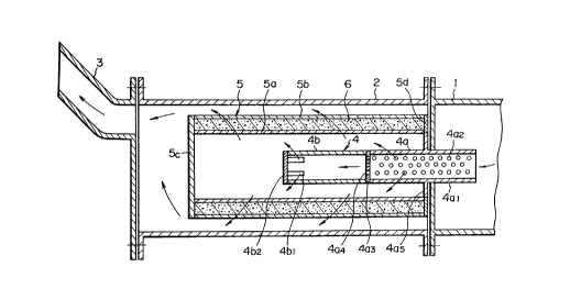
Referring to Fig. 1, such appaldl~ls for treating an exhaust gas from a light oil
combustion ~aldtus containing SO2 and NOX as the harmful components comprises
a muffler 1 connected with the light oil combustion apparatus, an exhaust pipe 2containing an exhaust gas-introducing pipe and an exhaust gas-exh~-sting pipe 4
provided with multiple gas dischd~ging small holes 4a2, 4a4, a plurality of gas escape
ports 4bl, a filter pipe S, and a gas outlet pipe 3 connected with the exhaust pipe 2.
"~ ~ 0 5 ~i 0 7 9
The filter pipe 5 is composed of an inner layer filter pipe Sa and an outer
layer filter pipe 5b, a particularly-specified activated carbon 6 packed in the space
between the inner layer filter pipe 5a and the outer layer filter pipe Sb, and a blind
plate 5c blocking one end of the filter pipe S. An exhaust gas-introducing pipe and
S an exhaust gas-exh~--sting pipe 4 is each provided in the inner space of the inner layer
filter pipe Sa.
The exhaust gas-introducing and exhaust gas-e~h~-lsting pipe 4 preferably
comprises a perforated pipe portion 4a having multiple small holes 4a2 for passing gas
at the pipe wall 4al, a rear end wall 4a3 provided with multiple small holes 4a4 for
passing gas, a pipe portion 4b provided with a plurality of gas escape ports 4bl at the
pipe wall near the end portion, and a blocking plate 4b2 at the top end portion.The activated carbon should have the following char~ct~ri~tics: it comprises
both carbon microcrystals which are irregularly arranged and difficultly-graphitizable
carbon which comprises difficultly-graphitizable cro~clinkin~ lattices in the gaps
among the carbon microcrystals. It has a pencil hardness of from B to 6B (preferably
2B to 4B), a pore size of 100-400 A (preferably 200 - 350 A), a specific surface area
of lS0-S00 m2/g (preferably 200 - 400 m2/g), and a pore volume of 1.3-S.0 ml/g
(preferably 1.4 - 3.0 ml/g). An activated carbon produced by burning waste tires is
most preferable.
An exhaust gas from a light oil combustion appa-dllls is introduced into an
exhaust gas-introducing and exhaust gas~rh~lsting pipe through a muffler, passesthrough many gas discha~ g small holes of the perforated pipe portion and a
plurality of gas escape ports and diffuses into the activated carbon layer through a
metal net of an inner layer filter pipe (for example, a 3 mm mesh).
_ ~05~079
The exhaust gas is treated in the inner layer portion of the activated carbon,
that is, SO2 and NOX are adsorbed to the activated carbon, and SO2 and NOX whichare not adsorbed by this primary tre~tmPnt are subjected to a secondary treatment in
the outer layer portion of the activated carbon for adsorbing the rem~ining SO2 and
S NO,~ before the exhaust gas passes through a metal net of the outer layer filter pipe
(for example, a 2 mm mesh).
The concentrations of SO2 and NOX in the exhaust gas having passed the outer
layer filter pipe is much lower than those before the treatment.
Further, according to a method for treating an exhaust gas from a light oil
combustion apparatus, the harmful components, e.g., SO2, NOX and the like, are
removed by adsorbing the harmful components to the above-described activated
carbon which is produced by burning waste tires, or to an activated carbon having a
particular structure and particular characteristics.
One end of a muffler 1 is connected with a flue of a diesel engine using a lightoil and the other end of muffler 1 is connected with one end of an exhaust pipe 2.
The other end of muffler 1 is connected with one end of an exhaust pipe 2. The
other end of exhaust pipe 2 is connected with a gas outlet pipe 3.
Muffler 1, exhaust pipe 2 and gas outlet pipe 3 are connected by fixing the
flanges with bolts and nuts.
An exhaust gas-introducing and exhaust gas-exh~ ting pipe 4 (made of metal)
is colllposed of a pc;,rol~ted pipe portion 4a provided with an opening at the forward
end (right end in Fig. 1), a pipe wall 4al having many small holes 4a2, a rear end lid
4a3 (left end in Fig. 1) having many small holes 4a~, and a pipe por~on 4b of which
the forward end is connected with rear end lid 4a3 and which has a plurality (for
~s
~ ~ 5 ~ ~ 7 9
example, four) of gas escape ports 4b, at the pipe wall near the end portion and a
blocking plate 4b2 at the top end portion.
Pelroldted pipe portion 4a is provided with a flange 4a5, for example, at
approximately the middle portion in the longitll~lin~l direction, and the flange 4aS is
fixed to a flange of muffler 1 (for example, using bolts and nuts).
Filter pipe S is composed of inner layer filter pipe 5a made of a 3 mm mesh
metal net (for example, made of stainless steel), outer layer filter pipe Sb made of a
2 mm mesh metal net (for example, made of stainless steel), an activated carbon layer
6 packed in the space between the pipes 5a and 5b, a blind plate 5c (for example,
made of st~inless steel) blocking the end portion and an annular frame plate 5d
supporting the inner and outer pipes 5a and 5b and activated carbon layer 6 which is
fixed to an end of the filter pipe opposite to blind plate 5c.
Filter pipe 5 is removably fitted to flange 4a5 of perforated pipe portion 4a bymeans of annular frame plate 5d.
In the above-mentioned apparatus for treating the exhaust gas, the exhaust gas
entering muffler 1 from a diesel engine flows into pelrol~ted pipe portion 4a ofexhaust gas introducing and exh~l-sting pipe 4 and then one part of the gas is
discharged through small holes 4a2 (for ex~mple, 9 mm in ~ meter) and is diffused
into activated carbon layer 6 through inner layer filter pipe 5a of filter pipe 5.
The other part of the gas flows into pipe portion 4b through small holes 4a4
(for example, 3 mm in diameter) at a large flow rate, collides against blocking plate
4b2, discha.~es through gas escape ports 4bl, then passes through inner layer filter
pipe 5a and diffuses into activated carbon layer 6. In this diffusion step, the diffusion
speed is so large (due to the high flow speed into pipe portion 4b) that the diffusion
~ 0; 5 6 ~ 7 9
of the exhaust gas which passes through small holes 4a2 and diffuses previously into
activated carbon layer 6 than this exhaust gas which passes through gas escape ports
4bl, is f~ilit~te~.
The exhaust gas diffuses into the inner layer portion of the activated carbon
6 and SO2 and NOX are adsorbed, but the lc~ inil~ SO2 and NOX are adsorbed in the
outer layer portion of the activated carbon 6, and then discharged to exhaust pipe 2
through the outer layer filter pipe Sb.
The exhaust gas thus treated leaves exhaust pipe 2 and is discharged to
atmosphere through gas outlet pipe 3. When an activated carbon produced by
burning waste tires, having average 3 mm in size was used in the above-mentionedexample where filter pipe S comprised inner layer filter pipe Sa composed of 3 mm
mesh metal net and outer layer filter pipe Sb composed of 2 mm mesh metal net, SO~
concentration of 42 p.p.m. and NO2 concentration of S9 p.p.m. in an exhaust gas fed
decreased to 25 p.p.m. and 24 p.p.m. after the treatment, respectively, that is, they
lS were decreased by 40% and 60%, respectively. Further, under the similar
conditions, 70 p.p.m. NO2 and 29 p.p.m. SO2 in an exhaust gas from a light oil
combustion were reduced to 17 p.p.m. NO2 and 6 p.p.m. SO2, fespe~ ely, after thetre~tm~nt
Activated carbon produced by burning waste tires can be used in the present
invention. An example of such activated carbon is disclosed in J~p~nese Patent
Application Laid-Open No. Hei 1-127812 (1989) in which waste tires are burned asa fuel for a boiler and the resulting cinder can be used as an activated carbon.Activated carbon used in aspect of this invention may be preferably produced by
burning waste tires under particular conditions as shown below. Thus, the activated
~O~Q79
,.....
carbon used in aspects of the present invention can be produced by burning waste
tires con~ ing metal cords, e.g., steel cords, silicon steel cords, and the like at 400 -
900~C, preferably 700 - 800~C, in the presence of oxygen and in the further
presence of CO2 and water vapour.
Air used for the combustion of the waste tires is preferably of high humidity,
for example, having a relative humidity of at least 60%; if desired, water is added
to the combustion atmosphere in an appro~liate way.
After forrnation of the activated carbon, metal cord fragments are removed,
for example, by using a magnet. Then the resulting activated carbon particles are
10 subjected to screening to obtain the particles in a desired particle size range.
Therefore, pelletization is not nece.ss~ry. Naturally, if necessary, particles of a size
less than the desired particle size may be pelleti7e~ to produce desired particles.
This production procedure is quite different from prior art methods; it differs
from a method comprising strongly heating a carbon-co~ g material in the
15 absence of air (oxygen) to effect dry ~ till~tion followed by adding active hydrogen;
it differs also from a method comprising fully carbonizing a carbonaceous m~teri~l
and then activating the resulting carbon by steam or a treatment with chemicals.
As is clear from above, the activated carbon of an aspect of the present
invention can be produced without a multiple-step method including an activation step
20 or complicated procedure as in conventional methods.
The mech~ni~m of producing the activated carbon of the present invention
having the excellent prop~.lies in a single step is not clearly understood. Although
it is not desired to limit the invention to any particular theory, it is believed that the
metal cord (a twisted thin metal wire) is broken into fragments during the combustion
~ ~ O 5 ~ ~ 7 9
and is scattered into the waste tire m~t~ri~l~ to act in a catalyst-like manner or to act
physically on the materials; further CO2 and water present in the combustion
atmosphere simultaneously activate the carbonaceous material.
The amount of the metal cord is preferably at least 1/3 times the weight of the
5 waste tires. When the amount is less than 1/3 times, the reslllting adsorption ability
is poor. More preferably, the amount is from 4/10 times to 6/10 times the weight
of the waste tire.
In aspects of the present invention, the activated carbon preferably used has
a particular structure and particular characteristics, that is, the activated carbon has
pencil hardness of from B to 6B, preferably from 2B to 4B, a pore size of 100 - 400
A, preferably 200 - 350 A, a specific surface area of 150 - 500 m2/g, preferably 1.4 -
3.0 ml/g, and if desired, CEC of 8 - 13, preferably 9 - 12. The activated carbon
comprises both carbon microcrystals irregularly arranged and difficultly graphitizable
carbon which comprises difficultly graphitizable crosclinking lattices in the gaps
among the carbon microcrystals.
In the above, CEC (cation exchange capacity) defines a capacity of substitlltin~
a base.
Fig. 2 shows an electron photomiclo~ld~h of the activated carbon used in
aspects of the present invention. The m~gnific~tion is 1000 times. This shows large
20 pores, a large pore volume and the irregular arrangement.
~'.
2 ~) 5 ~ U 7 9
The following table is given to c~nlpale the activated carbon used in an aspect
of the present invention with a commercially-available activated carbon.
Activated carbon Commercially
of the present available acti-
invention vated carbon
Pencil hardness B - 6B H
Pore size 100 - 400 A 23.5 - 32.7 A
Specific surface area 150 - 500 m2/g 900 - 1010 m2/g
Pore volume 1.3 - 5.0 ml/g 0.60 - 1.17 ml/g
CEC 8 - 13 1 - 7
As is clear from the above table, the activated carbon used in an aspect of the
present invention has a lower hardness, larger pore size and larger pore volume than
a commercially-available activated carbon, and can adsorb large particles and
molecules. As shown by the electron photomicrographic structure, the activated
carbon used in an aspect of the present invention does not seem to deodorize or to
decolour due to its small specific surface area. However, it can surprisingly exhibit
excellent deodorizing and decolouring functions. This appears to be attributable to
the large pore size and volume.
The activated carbon used in an aspect of the present invention and
commercially-available activated carbon are further col.,paled as to adsorbability in
the following:
a. Activated Carbon Used In An Aspect of the Present Invention
Oil: adsorbed
Fungi: adsorbed
Ammonia odour: adsorbed
2~6~9
~._
13
Speed of deodorizing: very fast
Decolouring (Methylene Blue): very fast
b. Commercially-available Activated Carbon
Oil: not adsorbed
Fungi: not adsorbed
Ammonia odour adsorbed with difficulty
Speed of Deodorizing: slow; taking a long time
Decolouring (Methylene Blue): ordinary
The activated carbon used in an aspect of the present invention produced by
10 burning waste tires contains, for example, the following components and shows the
following pH.
Component % By Weight
Moisture 0.43 - 0.61
Carbon (C) 53.8 - 62.9
Total Nitrogen (T-N) 0.244 - 0.293
Phosphoric Acid (P2O5) 0.584 - 0.611
Potassium (K2O) 0.525 - 0.574
Calcium (CaO) 4.62 - 4.69
Magnesium (MgO) 0.665 - 0.670
Sulphur (S) 0.31 - 0.37
Vaporizable matter (mostly) balance
Carbon ratio (C/N) 220 - 226
pH (H20) 10.15 - 10.44
~0~6û79
,.,
The activated carbon is soft (low pencil hardness), but the structure strength
is high since the carbon ratio (C/N) relating to the bonding force is as high as 200.
On the other hand, the carbon ratio of commercially-available activated carbon is 70.
As described above, the activated carbon having a particular structure and
5 particular characteristics may be produced by burning waste tires, preferably, under
the above-mentioned particular conditions. The activated carbon has a large pore
volume and, due to the large pore volume, molecules of sulphur components and
nitrogen components are adsorbed at a high speed. Since the pore volume is large,
adsorption can be effected within a short time in correspondence with the molecular
10 structures of SO2 and NOx-
Furthermore, as mentioned above, the activated carbon used in the method andapparatus of aspects of the present invention can be produced from waste tires
disposal of which is an environmPntal problem these days. Therefore, the activated
carbon can be produced at low cost and the disposal problem of waste tires can be
15 also solved by aspects of the present invention.