Note: Descriptions are shown in the official language in which they were submitted.
- 20~63~7
Docket No. 1079-AR-FH
IMPROVED HIGH PRESSURE FLUID REGUhATOR
BACKGROUND OF THE INVENTION
This invention relates generally to fluid
handling and more particularly to high pressure fluid
pre~sure regulation.
Dispensing fluids for industrial applications
05 requires accurate control of pressure in order to
provide accurate distribution of the fluids in the
process. For paints, adhesives, and other high
viscosity fluids, distribution pressures of
approximately 3,000 psi are frequently required.
This has become increasingly true as suppliers of
these fluids have minimized the solvent content of
these mixtures in response to demands for reduction
in health and fire hazards in the workplace. As
solvent contents have decreased, the abrasive nature
of the suspended solids has become more significant
and has begun to adversely affect the service life of
the fluid pressure regulators employed in the
system.
Typically, a fluid pressure regulator consists
of an inlet, an outlet, and a valve placed in the
connecting path between the inlet and outlet. A
::
~ '` - ~ , '
20~6317
Docket No. 1079-AR-F~
valve closure element is usually biased against the
valve seat and is controlled by a stem or other
mechanism which is, in turn, adjustably biased
counter to the closure element by means of a spring
05 acting on a diaphragm and/or piston which enables the
regulator to maintain a constant outlet pressure
despite fluctuations in inlet pressure. The piston
is adjustably spring biased and is reciprocable
within a cylindrical bore in the regulator cover
plate. Without a diaphragm, the bore reguires a
circumferential lip seal in order to prevent leakage
of the fluid between the piston and the bore. To
function properly against such a seal, the piston
requires a very fine finish of the order of 10
microinches or less. Such a finish is expensive to
produce and is very easily damaged by corrosion or
mechanical injury. Moreover, in the presence of
highly abrasive low solvent suspensions, both the
seal and the piston finish deteriorate due to sliding
contact.
For high pressures, a combination of diaphragm
with piston provides more positive sealing.
Durability of the diaphragm compared to the lip seal
is generally superior since the diaphragm is exposed
to flexure rather than sliding wear.
, . .
20563 1 7
Reduction of solvent content has increased the
viscosity of the working materials so that they require
higher pumping pressures and, consequently, regulators
designed for those pressures. Regulators which were
designed to perform in the range of 1000 psi to 1500
psi experienced short service life using the high
solids/low solvent materials presently available.
Increasing wall thicknesses and spring stiffness alone
is not sufficient to upgrade a medium pressure
regulator for use in the 3000 psi range of service
peressures commonly encountered.
Typically, high pressure regulators employ a
diaphragm as well as a piston in a bore of the
diaphragm backup plate. To protect the diaphragm from
cutting, the edges of the piston and the bore of the
backup plate are commonly given a radius. The
diaphragm commonly consists of fabric mesh reinforced
rubber for flexibility and a layer, bonded onto the
pumped fluid side of a chemically resistant material.
"O" ring seals are commonly used between the diaphragm,
the stem, and the regulator housing.
In the prior art, the stem and the piston are
bolted together to capture the one piece bonded
diaphragm and "O" ring seal between them. The
diaphragm is composed of a fabric reinforced rubber
layer and a chemical resistant layer. The piston
reciprocates within a bore of a backup plate. For ease
of assembly, a chamfer is provided as well as the
relatively loose fit between the bore and the piston
which are also radiused as previously described. An
"O" ring provides a seal between the diaphragm and the
housing.
In high pressure surface, this type regulator
will potentially experience the following problems:
- 3 -
,
205631 7
1. the short guide length of the bore between
the chamfer and radius on the backup plate can allow
the piston to cock slightly within the bore, and can
thus permit localized high pressure contact between
piston and backup plate and non-uniform flexure of the
diaphragm;
2. the large gap, behind the diaphragm, provided
by the radii of the backup plate and the piston, allows
wedging of the diaphragm into the large gap and
consequent excessive abrasion and flexural wear on the
diaphragm;
3. the relatively thin backup plate is subject
to slight deflection due to high pressure and thus
leakage of the working fluid around the seal between
the housing and the diaphragm;
4. the one piece bonded diaphragm, because of
the different flexural moduli of the two layers,
experiences intensified local stresses which cause
early failure;
5. in cases where a resonance causes vibration
of the piston within the backup plate bore, fretting
corrosion may become a significant problem and thus
exacerbate the other shortcomings of this design in a
high pressure application.
The foregoing illustrates limitations known to
exist in present fluid pressure regulators when used in
high pressure applications. Thus, it is apparent that
it would be advantageous to provide an alternative
directed to overcoming one or more of the limitations
set forth above. Accordingly, a suitable alternative
is provided including features more fully disclosed
hereinafter.
:~ '
, .. . .
205631 7
SUMMARY OF THE INVENTION
In one aspect of the present invention, this is
accomplished by providing a fluid pressure regulator
which has a body with a fluid inlet, a fluid outlet,
and a fluid passage communicating therebetween; a
variable valve positioned within the fluid passage and
having an orificed seat and a closure element biased
toward said orificed seat; provision for adjusting the
clearance between the seat and the closure element in
order to control fluid outlet pressure; and first and
second separate, imperforate, radially coextensive
diaphragms in mutual flat surface contact, for
maintaining a substantially constant outlet pressure
which is independent of fluctuations in fluid inlet
pressure.
According to the above broad aspect of the
present invention there is provided a fluid pressure
regulator which comprises a body having a fluid inlet,
a fluid outlet, and a fluid passage communicating
therebetween. A variable valve is positioned within
the fluid passage and has an orificed seat and a
closure element biased toward the orificed seat. Means
is provided for adjusting a clearance between the seat
and the closure element in order to control fluid
outlet pressure. Means including first and second
separate, imperforate, radially coextensive diaphragms
in mutual flat service contact is provided for
maintaining a substantially constant outlet pressure
which is independent of fluctuations in fluid inlet
pressure. A plurality of annular thickened zones are
formed in at least one of the diaphragms for sealing
between the first diaphragm and the valve stem and
between the first diaphragm and the regulator housing
body.
20563 1 7
According to a still further broad aspect of the
present invention there is provided the improvement in
a fluid pressure regulator of the type having a
regulator body with a fluid inlet, a fluid outlet, and
a fluid passage therebetween, a fluid flow valve
orifice in the fluid passage, a valve closure element,
a valve stem for controlling the closure element, a
piston means reciprocably movable within a bore of a
housing body cover for controlling the stem position,
and diaphragm means for preventing leakage of the
working fluid out of the fluid flow channel and for
adjusting the position of the valve closure element in
response to variations in the fluid inlet pressure.
The improvement comprises a first imperforate diaphragm
coextensive with the first imperforate diaphragm having
a high degree of flexibility and abrasion resistance
positioned between the first diaphragm and the housing
body cover. A plurality of annular thickened zones
formed in at least one of the first and second
diaphragms for sealing between the first diaphragm and
the valve stem and the first diaphragm and the
regulator body. A bore of sufficient length is
provided within the housing body cover and of
sufficiently close fit to the piston to prevent cocking
of the piston within the bore.
The foregoing and other aspects will become apparent
from the following detailed description of the
invention when considered in conjunction with the
accompanying drawing Figures.
BRIEF DESCRIPTION OF THE DRAWING FIGURES
Fig. 1 is a fragmentary cross-sectional view
which illustrates features of fluid pressure regulators
of the prior art;
.~
205631 7
Fig. 2 is an elevation cross section of the high
pressure fluid regulator of the present invention;
Fig. 3 is a fragmentary cross-sectional view to
illustrate detail of the critical features of the
present invention;
Fig. 4 is a cross sectional view which presents
an alternative embodiment of the diaphragm of the
present invention; and
Fig. 5 is a fragmentary cross-sectional view
which presents a variant of the diaphragm shown in Fig.
4.
DETAILED DESCRIPTION
Fig. 1 illustrates the features of a prior art
regulator previously described which is suitable for
use in low to medium pressure applications but has
shortcomings when used in high pressure applications.
This Figure presents a cross-sectional view of the
diaphragm piston interfacial area of a typical prior
art regulator showing the stem 6 and piston 5 bolted
together to capture the one-piece bonded diaphragm 1
and "O" ring seal 7 between them. The diaphragm 1 is
composed of a fabric reinforced rubber layer 3 and a
chemical resistant layer 2. The piston 5 reciprocates
within the bore 8 of a backup plate 4. As previously
described, for ease of assembly, a chamfer 11 is
provided as well as the relatively loose fit between
bore 8 and piston 5 which are also radiused as
previously described. The "O" ring 9 provides a seal
between diaphragm 1 and housing 14.
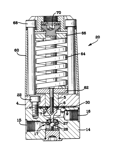
Fig. 2 shows a high pressure regulator 20 of the
present invention. It comprises a housing body 14, a
housing cover which also serves as diaphagm backup
20563~ 7
Docket No. 1079-AR-FH
plate 4, a bonnet 60, a diaphragm tensioning spring
64 bounded at the top and bottom by spring keepers 66
and 62, bonnet bolts 68, and adjusting screw 70.
~onnet bolts 68 secure bonnet 60 through diaphragm
05 backup plate 4 and are threaded into housing body 14.
Plate 4 is also secured to housing body 14 by backup
plate bolts 22. Piston 5 is secured to spring keeper
62 and to stem 6 such that diaphragm 30 is trapped
between piston 5 and stem 6. "0" rings 7 and 9
provide fluid seals between the diaphragm assembly 30
and stem 6 and diaphragm assembly 30 and housing body
14, respectively. "0" rings are used in this example
but it should be understood that any appropriate seal
ring arrangement is satis~actory.
High pressure fluid enters the regulator through
inlet 15, passes through variable valve 17 which
comprises closure element 26 and valve seat 27,
passes around stem 6 and exits through outlet 16.
Pressure regulation is accomplished by turning
adjusting screw 70 to compress diaphragm tensioning
spring 64. This drives spring keeper 66 downward so
as to increase the spring pressure on spring keeper
62 which forces piston 5 and rigidly connected stem 6
downward to displace closure element 26 from seat 27,
thus opening variable valve 17. The system pressure
2~6~7
Docket No. 1079-AR-FH
downstream of valve 17 is inversely proportional to
the amount of pressure drop through valve 17. This ~
downstream pressure acts upon diaphragm 30 and piston
5 to force them upward counter to the direction of
05 force exerted by diaphragm tensioning spring 64.
Thus, after a very brief "hunting" interval, the two
oppo6ing forces are balanced and steady state
operation is achieved. So long as the inlet pressure
remains constant, and so long as the outlet demand
remains constant, the positions of all these movable
elements remain stationary. Should inlet pressure
decrease, the resulting decrease in downstream
pressure will cause piston and stem to move downward,
thereby further opening valve 17 and restoring the
outlet pressure to the set point. The converse is
true for increases of inlet pressure as well.
Desired pressures are set by turning adjusting screw
70 to force upper spring keeper 66 downward to
increase pressure and to pull keeper 66 upward to
decrease pressure.
Fig. 3 is a fragmentary enlarged partially
sectional view showing greater detail of critical
elements of the present invention. It is now
apparent that diaphragm assembly 30 comprises a
backup member which is a flexible elastomeric
2~6317
Docket No. 1079-AR-FH
diaphragm 35 lying against the piston 5 and backup
plate 4, and a chemically resistant diaphragm 40
lying against flexible diaphragm 35 and shielding it
from any corrosive properties of the working fluid.
05 It should be noted that diaphragms 35 and 40 are not
bonded together but are radially coextensive and in
mutual flat surface contact wit:h each other. This
nonbonded contact improves the flexibility of the
diaphragm assembly by permitting limited slippage
between the diaphragms during flexure. This reduces
the tensile and compressive stresses experienced by
the diaphragm surfaces and, thus, improves the
fatigue lives of the diaphragms. The gently tapered
relief 16 on backup plate 4 around the circumference
of bore 8 together with small radius 18 on piston 5
combined to produce a very small gap behind diaphragm
35, and they thus permit the diaphragm to flex over a
longer distance and, thus, to flex less sharply. ~
Note that chamfer 11 is still provided for ease of
assembly. However, the fit of piston 5 within the
bore in backup plate 4 is sufficiently close so that,
when combined with the larger guide length resulting
from increasing the thickness of diaphragm backup
plate 4, there is virtually no tendency for the
piston to cock in the bore. This eliminates damage
caused by nonuniform flexing and by misalignment of
regulator components.
. . ,.: , .. , . . - ~: .. . .. .. . - . ...
2~5~317
Docket No. 1079-AR-FH
Coating A on the bore of backup plate 4 and
coating B on the lateral circumferential surface of
piston 5 are provided to ensure that surfaces which
may be subject to vibratory oscillation against each
05 other are not of the same metal. This reduces the
tendency for fretting corrosion to occur, thereby
extending the service life of the piston 5 and of the
backup plate 4. It should be noted that it is not
necessary to coat both surfaces in order to satisfy
the different metal requirement. For example, if
piston 5 were made of steel and backup plate 4 ware
made of bronze, the different metal requirement would
be met. If, however, both were made of bronze or
both were made of steel, it would be desirable to
coat one or the other to eliminate the fretting
corrosion problem. Depending on the circumstances,
coatings such as hard chromium electroplate, nickel
electroplate, electroless nickel, or other relatively
hard plated surfaces may be used. By avoiding the
use of similar metals or soft metals on the
contacting surfaces the tendency toward fretting
corrosion due to reciprocating or oscillating
vibratory motion under high pressures at the contact
surfaces will be reduced and service life of the
regulator improved.
:
2~63~7
Docket No. 1079-AR-FH
Finally, the increased thickness of backup plate
4 reduces the tendency of the backup plate to deflect
under pressure and thereby prevents initiation of
leakage past "0" ring seal 9 between diaphragm 40 and
05 the housing body. This freedom from deflection also
contributes to the alignment stability of the piston
which was earlier discussed from the viewpoint of
improved guide length.
Figs. 4 and 5 are fragmentary sectional views to
show detail of two alternative diaphragm designs
which incorporate integral "0" rings. Fig. 4 shows
the integral "0" rings 39 and 37 formed on backup
diaphragm 35, while Fig. 5 shows "0" rings 39 and 37
integrally formed on chemically resistant diaphragm
40. The option chosen will depend on the materials
chosen for the diaphragms, the size of the diaphragms
and of the regulator, the ser~ice pressure intended,
and the characteristics of the fluid being sealed.
The preferred embodiment for flexible diaphragm 35
employs a thermoplastic elastomer while the
chemically resistant diaphragm 40 employs a
fluoropolymer.
The present invention successfully addresses all
of the shortcomings previously noted. The major
2~631~
Docket No. 1079-AR-FH
improvement over the prior art stems from employment
of independent separate diaphragms for the chemical
resistance requirements and for the flexibility and
abrasion resistance requirements. The improved fit
05 of the piston within the bore of the backup plate
together with the increased guide length achieved by
increasing the thickness of the backup plate improves
alignment of the regulator components and reduces
damage formerly attributable to misalignment and
consequent high localized stresses. Provision of a
coating on the piston and/or the bore of the backup
plate provides resistance to fretting corrosion which
can shorten regulator life. Finally, employing
diaphragms having integrally formed seal rings
simplifies assembly and assures proper placement of
the rings.