Language selection

Search

Patent 2056327 Summary

Third-party information liability

Some of the information on this Web page has been provided by external sources. The Government of Canada is not responsible for the accuracy, reliability or currency of the information supplied by external sources. Users wishing to rely upon this information should consult directly with the source of the information. Content provided by external sources is not subject to official languages, privacy and accessibility requirements.

Claims and Abstract availability

Any discrepancies in the text and image of the Claims and Abstract are due to differing posting times. Text of the Claims and Abstract are posted:

  • At the time the application is open to public inspection;
  • At the time of issue of the patent (grant).
(12) Patent Application: (11) CA 2056327
(54) English Title: LOCKER PROVIDING AN EFFICIENT VENTILATION OF ITS CONTENT
(54) French Title: ARMOIRE ASSURANT L'AERATION EFFICACE DE SON CONTENU
Status: Deemed Abandoned and Beyond the Period of Reinstatement - Pending Response to Notice of Disregarded Communication
Bibliographic Data
Abstracts

English Abstract


ABSTRACT
The locker comprises a back wall, a top wall, a
bottom wall, a front wall and two side walls to form a
chamber. The front wall is provided with a door by which a
user can have access to the chamber. The front wall forms
with the side walls two lateral vertical edges that are
respectively provided with two wire meshes along at least a
portion of their length whereby air circulation inside the
chamber can be provided by means of the two wire meshes.


Claims

Note: Claims are shown in the official language in which they were submitted.

The embodiments of the invention in which an
exclusive property or privilege is claimed are defined as
follows:
1. A locker comprising a back wall, a top wall, a
bottom wall, a front wall and two side walls to form a
chamber, said front wall being provided with a door by which
a user can have access to said chamber, said front wall
forming with said side walls two lateral vertical edges that
are respectively provided with two ventilating means along
at least a portion of their length whereby air circulation
inside said chamber can be provided by means of said two
ventilating means.
2. A locker according to claim 1, wherein each of said
ventilating means are constituted of a wire mesh.
3. A locker according to claim 2, wherein each of said
lateral vertical edges is provided along all of their length
with one of said wire meshes.
4. A locker according to claim 1, in combination with
at least another locker comprising a back wall, a top wall,
a bottom wall, a front wall and two side walls to form
another chamber, the front wall of said other locker being
provided with a door by which the user can have access to
said other chamber, the front wall and the side walls of
said other locker forming two lateral edges that are
respectively provided with two ventilating means along at
least a portion of their length, said lockers having one of
their side walls and one of their ventilating means that are
common.

5. Lockers according to claim 4, wherein each of said
ventilating means are constituted of a wire mesh, and
wherein each of said lateral vertical edges is provided
along all of their length with one of said wire meshes.
6. Lockers according to claim 5, wherein said common
wire mesh is an elongated member of U-shaped cross section
having its side sections facing respectively each of the two
adjacent chambers, and its linking section interposed
between the two adjacent front walls.
7. Lockers according to claim 6, wherein said common
wire mesh is mechanically connected to the common side wall
by means of a rigid element having a U-shaped rear side
adapted to receive an edge of the common side wall and a
front side provided with lateral recesses adapted to receive
respectively edges of the common wire mesh.
8. Lockers according to claim 7, wherein said rigid
element is provided with a lateral recess by which a locking
member can be fixed onto said rigid element to cooperate
with a locking device fixed on the corresponding door.
9. Lockers according to claim 1, 2, 3, 4, 5, 6, 7 or 8,
wherein all of said walls are made of plastic laminated
panels.
10. Locker according to claim 2 or 5, wherein each
of said wire meshes is made of cold laminated steel, of
galvanized steel or of stainless steel.

Description

Note: Descriptions are shown in the official language in which they were submitted.


Z~S5~27
FIEL~ OF THL INVENTION
The present invention relates to lockers and has to
do more particularly with lockers where an adequate air
circulation is needed~
BRI~F D~SCRIPTION OF TH~ PRI~R ~RT
Known in the art, there is the U.S. patent
no. 3,133,772 by A. BRANDES et al. in which there is
described standard lockers provided with front narrow louver
openings by which a certain ventilation of the inside
portion of the locker is obtained. One drawback wlth this
locker i5 that the ventilatien that is obtained is not
~5 sufficient for certain applications.
Also known in the art, there is the U.S. patent
no. 3,231,322 of R.E. SHAW in which there is described
pilfer-proof storage rack and containers. Very good
ventilation ls obtained with such containers. The drawback
with these containers is that the content of the container
is always visible which, for many applications such as in
gymnasiums, is not wanted.
Also known in the art are the following patents:
U.S. patents nos. 1,842,286 (C.H. POTTER), 2,172,266 (E.H.
2g WHITAKER) and 3,819,246 (H.A. LIST). None of those patents
can provids a locker whsre its content is not visible from
the outside, with an effiaient ventilation.
An ob~ect of the present invention is to provide a
locker where the content of the locker is not visible from
the outside, and where a very efficient air circulation of
the locker interior is obtained.

2(;5S3~7
SUHMARY OF ~HE INV~NTION
According to the present invention, there is
provided a locker comprising a back wall, a top wall, a
bottom wall, a front wall and two side walls to form a
chamber, said front wall being provided with a door by which
a user can have accèss to said chamber, said front wall
forming with said side walls two lateral vertical edges that
are respectively provided with two ventilating means along
at least a portion of their length whereby air circulation
inside said chamber can be provided by means of said two
ventilating means.
The objects, advantages and features of the present
invention will become more apparent upon reading of the
following non restrictive description of preferred
embodiments thereof, given with reference to the
accompanying drawings.
B~IFF D~SCRIPTION OF TH~_DRAWINGS
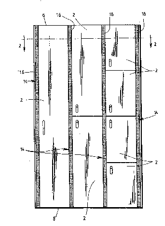
Figure 1 is a front view of several adjacent lockers
according to the present invention.
Figure 2 is a cross-sectional view of the lockers
shown in Figure 1, along lines 2-2.
Figure 3 is an enlarged illustration of a portion of
the view shown in Figure 2.
~ET~ BscRIpTIoN OF T~E PRFFERR~D EMBODIMFNT
Referring now to Figures 1 and 2, there is shown
several lockers 2 wherein each locker 2 comprises a back
wall 4, a top wall 6, a bottom wall 8, a front wall lO and
two side walls 11 to form a chamber 12. The front wall 10 is

;~C`~ 7
provided with a door by which a user can have access to the
chamber 12. The front wall 10 forms with the side walls 11
two lateral vertical edges 14 that are provided with wire
meshes along their length whereby air airculation inside the
chamber 12 is provided by means of the two wire meshes o~
each locker. Please note that it is not necessary that each
of the wire meshes be provided along all the length of the
lateral edges, sometimes, it is sufficient to provide only
a portion of the lateral edges with a wire mesh. As it can
be æeen ~rom Figures 1 and 2, the lockers have at least one
of their side walls and one of their wire meshes that are
common.
Referring now to Figure 3, which is an enlarged view
of a portion o~ Figure 2, ik can be seen that each of the
common wire ~eshes is an elongated member of U-shaped cross
section having its side sections 26 facing respectively each
of the two adjacent chambers 12, and its linking section 28
interposed between the two adjacent front walls 10.
Each of the common wire meshes is mechanically
connected to the corresponding co~mon side wall 11 by means
of a rigid element 28 having a U-shaped rear side adapted to
receive the edge of the c~mmon side wall 11, and a front
- side provided with lateral recesses adapted to receive
respectively edges of the common wire mesh 16. Also, the
rigid element 28 is provided with lateral recesses 30 by
which the locking member 32 is fixed onto the rigid element
to cooperate with the loaking device 34 fixed on the
corresponding door.
The walls of the loaker can be made of different
material, but it has been found convenient that these walls
be ~ade of plastic laminated panels. Also, it has been found
convenient that the wire meshes be made of cold laminated

2C`~iS3 '7
steel, of galvanized steel or of stainless steel. The rigid
element 28 is made of aluminum 6063-T5 by extrusion.
Although the present invention has been described
hereinabove by way of a preferred embodiment thereof, it
should be pointed out that any modification to thls
preferred embodiment, within the scope of the appended
claims, is not deemed to change or alter the nature and
scope of the present invention.

Representative Drawing
A single figure which represents the drawing illustrating the invention.
Administrative Status

2024-08-01:As part of the Next Generation Patents (NGP) transition, the Canadian Patents Database (CPD) now contains a more detailed Event History, which replicates the Event Log of our new back-office solution.

Please note that "Inactive:" events refers to events no longer in use in our new back-office solution.

For a clearer understanding of the status of the application/patent presented on this page, the site Disclaimer , as well as the definitions for Patent , Event History , Maintenance Fee  and Payment History  should be consulted.

Event History

Description Date
Inactive: IPC from MCD 2006-03-11
Time Limit for Reversal Expired 1998-11-27
Application Not Reinstated by Deadline 1998-11-27
Deemed Abandoned - Failure to Respond to Maintenance Fee Notice 1997-11-27
Application Published (Open to Public Inspection) 1993-05-28

Abandonment History

Abandonment Date Reason Reinstatement Date
1997-11-27
Owners on Record

Note: Records showing the ownership history in alphabetical order.

Current Owners on Record
DECOLAM INC.
Past Owners on Record
MICHEL DALLAIRE
Past Owners that do not appear in the "Owners on Record" listing will appear in other documentation within the application.
Documents

To view selected files, please enter reCAPTCHA code :


To view images, click a link in the Document Description column (Temporarily unavailable). To download the documents, select one or more checkboxes in the first column and then click the "Download Selected in PDF format (Zip Archive)" or the "Download Selected as Single PDF" button.

List of published and non-published patent-specific documents on the CPD .

If you have any difficulty accessing content, you can call the Client Service Centre at 1-866-997-1936 or send them an e-mail at CIPO Client Service Centre.

({010=All Documents, 020=As Filed, 030=As Open to Public Inspection, 040=At Issuance, 050=Examination, 060=Incoming Correspondence, 070=Miscellaneous, 080=Outgoing Correspondence, 090=Payment})


Document
Description 
Date
(yyyy-mm-dd) 
Number of pages   Size of Image (KB) 
Abstract 1993-05-27 1 12
Claims 1993-05-27 2 64
Drawings 1993-05-27 2 49
Descriptions 1993-05-27 4 118
Representative drawing 1998-09-27 1 25
Courtesy - Abandonment Letter (Maintenance Fee) 1997-12-28 1 185
Reminder - Request for Examination 1998-07-27 1 129
Fees 1996-10-30 1 42
Fees 1995-11-06 1 47
Fees 1994-10-12 1 46
Fees 1993-10-27 1 42