Sélection de la langue

Search

Sommaire du brevet 2056327 

Énoncé de désistement de responsabilité concernant l'information provenant de tiers

Une partie des informations de ce site Web a été fournie par des sources externes. Le gouvernement du Canada n'assume aucune responsabilité concernant la précision, l'actualité ou la fiabilité des informations fournies par les sources externes. Les utilisateurs qui désirent employer cette information devraient consulter directement la source des informations. Le contenu fourni par les sources externes n'est pas assujetti aux exigences sur les langues officielles, la protection des renseignements personnels et l'accessibilité.

Disponibilité de l'Abrégé et des Revendications

L'apparition de différences dans le texte et l'image des Revendications et de l'Abrégé dépend du moment auquel le document est publié. Les textes des Revendications et de l'Abrégé sont affichés :

  • lorsque la demande peut être examinée par le public;
  • lorsque le brevet est émis (délivrance).
(12) Demande de brevet: (11) CA 2056327
(54) Titre français: ARMOIRE ASSURANT L'AERATION EFFICACE DE SON CONTENU
(54) Titre anglais: LOCKER PROVIDING AN EFFICIENT VENTILATION OF ITS CONTENT
Statut: Réputée abandonnée et au-delà du délai pour le rétablissement - en attente de la réponse à l’avis de communication rejetée
Données bibliographiques
Abrégés

Abrégé anglais


ABSTRACT
The locker comprises a back wall, a top wall, a
bottom wall, a front wall and two side walls to form a
chamber. The front wall is provided with a door by which a
user can have access to the chamber. The front wall forms
with the side walls two lateral vertical edges that are
respectively provided with two wire meshes along at least a
portion of their length whereby air circulation inside the
chamber can be provided by means of the two wire meshes.

Revendications

Note : Les revendications sont présentées dans la langue officielle dans laquelle elles ont été soumises.


The embodiments of the invention in which an
exclusive property or privilege is claimed are defined as
follows:
1. A locker comprising a back wall, a top wall, a
bottom wall, a front wall and two side walls to form a
chamber, said front wall being provided with a door by which
a user can have access to said chamber, said front wall
forming with said side walls two lateral vertical edges that
are respectively provided with two ventilating means along
at least a portion of their length whereby air circulation
inside said chamber can be provided by means of said two
ventilating means.
2. A locker according to claim 1, wherein each of said
ventilating means are constituted of a wire mesh.
3. A locker according to claim 2, wherein each of said
lateral vertical edges is provided along all of their length
with one of said wire meshes.
4. A locker according to claim 1, in combination with
at least another locker comprising a back wall, a top wall,
a bottom wall, a front wall and two side walls to form
another chamber, the front wall of said other locker being
provided with a door by which the user can have access to
said other chamber, the front wall and the side walls of
said other locker forming two lateral edges that are
respectively provided with two ventilating means along at
least a portion of their length, said lockers having one of
their side walls and one of their ventilating means that are
common.

5. Lockers according to claim 4, wherein each of said
ventilating means are constituted of a wire mesh, and
wherein each of said lateral vertical edges is provided
along all of their length with one of said wire meshes.
6. Lockers according to claim 5, wherein said common
wire mesh is an elongated member of U-shaped cross section
having its side sections facing respectively each of the two
adjacent chambers, and its linking section interposed
between the two adjacent front walls.
7. Lockers according to claim 6, wherein said common
wire mesh is mechanically connected to the common side wall
by means of a rigid element having a U-shaped rear side
adapted to receive an edge of the common side wall and a
front side provided with lateral recesses adapted to receive
respectively edges of the common wire mesh.
8. Lockers according to claim 7, wherein said rigid
element is provided with a lateral recess by which a locking
member can be fixed onto said rigid element to cooperate
with a locking device fixed on the corresponding door.
9. Lockers according to claim 1, 2, 3, 4, 5, 6, 7 or 8,
wherein all of said walls are made of plastic laminated
panels.
10. Locker according to claim 2 or 5, wherein each
of said wire meshes is made of cold laminated steel, of
galvanized steel or of stainless steel.

Description

Note : Les descriptions sont présentées dans la langue officielle dans laquelle elles ont été soumises.

Z~S5~27
FIEL~ OF THL INVENTION
The present invention relates to lockers and has to
do more particularly with lockers where an adequate air
circulation is needed~
BRI~F D~SCRIPTION OF TH~ PRI~R ~RT
Known in the art, there is the U.S. patent
no. 3,133,772 by A. BRANDES et al. in which there is
described standard lockers provided with front narrow louver
openings by which a certain ventilation of the inside
portion of the locker is obtained. One drawback wlth this
locker i5 that the ventilatien that is obtained is not
~5 sufficient for certain applications.
Also known in the art, there is the U.S. patent
no. 3,231,322 of R.E. SHAW in which there is described
pilfer-proof storage rack and containers. Very good
ventilation ls obtained with such containers. The drawback
with these containers is that the content of the container
is always visible which, for many applications such as in
gymnasiums, is not wanted.
Also known in the art are the following patents:
U.S. patents nos. 1,842,286 (C.H. POTTER), 2,172,266 (E.H.
2g WHITAKER) and 3,819,246 (H.A. LIST). None of those patents
can provids a locker whsre its content is not visible from
the outside, with an effiaient ventilation.
An ob~ect of the present invention is to provide a
locker where the content of the locker is not visible from
the outside, and where a very efficient air circulation of
the locker interior is obtained.

2(;5S3~7
SUHMARY OF ~HE INV~NTION
According to the present invention, there is
provided a locker comprising a back wall, a top wall, a
bottom wall, a front wall and two side walls to form a
chamber, said front wall being provided with a door by which
a user can have accèss to said chamber, said front wall
forming with said side walls two lateral vertical edges that
are respectively provided with two ventilating means along
at least a portion of their length whereby air circulation
inside said chamber can be provided by means of said two
ventilating means.
The objects, advantages and features of the present
invention will become more apparent upon reading of the
following non restrictive description of preferred
embodiments thereof, given with reference to the
accompanying drawings.
B~IFF D~SCRIPTION OF TH~_DRAWINGS
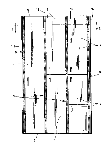
Figure 1 is a front view of several adjacent lockers
according to the present invention.
Figure 2 is a cross-sectional view of the lockers
shown in Figure 1, along lines 2-2.
Figure 3 is an enlarged illustration of a portion of
the view shown in Figure 2.
~ET~ BscRIpTIoN OF T~E PRFFERR~D EMBODIMFNT
Referring now to Figures 1 and 2, there is shown
several lockers 2 wherein each locker 2 comprises a back
wall 4, a top wall 6, a bottom wall 8, a front wall lO and
two side walls 11 to form a chamber 12. The front wall 10 is

;~C`~ 7
provided with a door by which a user can have access to the
chamber 12. The front wall 10 forms with the side walls 11
two lateral vertical edges 14 that are provided with wire
meshes along their length whereby air airculation inside the
chamber 12 is provided by means of the two wire meshes o~
each locker. Please note that it is not necessary that each
of the wire meshes be provided along all the length of the
lateral edges, sometimes, it is sufficient to provide only
a portion of the lateral edges with a wire mesh. As it can
be æeen ~rom Figures 1 and 2, the lockers have at least one
of their side walls and one of their wire meshes that are
common.
Referring now to Figure 3, which is an enlarged view
of a portion o~ Figure 2, ik can be seen that each of the
common wire ~eshes is an elongated member of U-shaped cross
section having its side sections 26 facing respectively each
of the two adjacent chambers 12, and its linking section 28
interposed between the two adjacent front walls 10.
Each of the common wire meshes is mechanically
connected to the corresponding co~mon side wall 11 by means
of a rigid element 28 having a U-shaped rear side adapted to
receive the edge of the c~mmon side wall 11, and a front
- side provided with lateral recesses adapted to receive
respectively edges of the common wire mesh 16. Also, the
rigid element 28 is provided with lateral recesses 30 by
which the locking member 32 is fixed onto the rigid element
to cooperate with the loaking device 34 fixed on the
corresponding door.
The walls of the loaker can be made of different
material, but it has been found convenient that these walls
be ~ade of plastic laminated panels. Also, it has been found
convenient that the wire meshes be made of cold laminated

2C`~iS3 '7
steel, of galvanized steel or of stainless steel. The rigid
element 28 is made of aluminum 6063-T5 by extrusion.
Although the present invention has been described
hereinabove by way of a preferred embodiment thereof, it
should be pointed out that any modification to thls
preferred embodiment, within the scope of the appended
claims, is not deemed to change or alter the nature and
scope of the present invention.

Dessin représentatif
Une figure unique qui représente un dessin illustrant l'invention.
États administratifs

2024-08-01 : Dans le cadre de la transition vers les Brevets de nouvelle génération (BNG), la base de données sur les brevets canadiens (BDBC) contient désormais un Historique d'événement plus détaillé, qui reproduit le Journal des événements de notre nouvelle solution interne.

Veuillez noter que les événements débutant par « Inactive : » se réfèrent à des événements qui ne sont plus utilisés dans notre nouvelle solution interne.

Pour une meilleure compréhension de l'état de la demande ou brevet qui figure sur cette page, la rubrique Mise en garde , et les descriptions de Brevet , Historique d'événement , Taxes périodiques et Historique des paiements devraient être consultées.

Historique d'événement

Description Date
Inactive : CIB de MCD 2006-03-11
Le délai pour l'annulation est expiré 1998-11-27
Demande non rétablie avant l'échéance 1998-11-27
Réputée abandonnée - omission de répondre à un avis sur les taxes pour le maintien en état 1997-11-27
Demande publiée (accessible au public) 1993-05-28

Historique d'abandonnement

Date d'abandonnement Raison Date de rétablissement
1997-11-27
Titulaires au dossier

Les titulaires actuels et antérieures au dossier sont affichés en ordre alphabétique.

Titulaires actuels au dossier
DECOLAM INC.
Titulaires antérieures au dossier
MICHEL DALLAIRE
Les propriétaires antérieurs qui ne figurent pas dans la liste des « Propriétaires au dossier » apparaîtront dans d'autres documents au dossier.
Documents

Pour visionner les fichiers sélectionnés, entrer le code reCAPTCHA :


Pour visualiser une image, cliquer sur un lien dans la colonne description du document (Temporairement non-disponible). Pour télécharger l'image (les images), cliquer l'une ou plusieurs cases à cocher dans la première colonne et ensuite cliquer sur le bouton "Télécharger sélection en format PDF (archive Zip)" ou le bouton "Télécharger sélection (en un fichier PDF fusionné)".

Liste des documents de brevet publiés et non publiés sur la BDBC .

Si vous avez des difficultés à accéder au contenu, veuillez communiquer avec le Centre de services à la clientèle au 1-866-997-1936, ou envoyer un courriel au Centre de service à la clientèle de l'OPIC.

({010=Tous les documents, 020=Au moment du dépôt, 030=Au moment de la mise à la disponibilité du public, 040=À la délivrance, 050=Examen, 060=Correspondance reçue, 070=Divers, 080=Correspondance envoyée, 090=Paiement})


Description du
Document 
Date
(aaaa-mm-jj) 
Nombre de pages   Taille de l'image (Ko) 
Abrégé 1993-05-27 1 12
Revendications 1993-05-27 2 64
Dessins 1993-05-27 2 49
Description 1993-05-27 4 118
Dessin représentatif 1998-09-27 1 25
Courtoisie - Lettre d'abandon (taxe de maintien en état) 1997-12-28 1 185
Rappel - requête d'examen 1998-07-27 1 129
Taxes 1996-10-30 1 42
Taxes 1995-11-06 1 47
Taxes 1994-10-12 1 46
Taxes 1993-10-27 1 42