Language selection

Search

Patent 2056559 Summary

Third-party information liability

Some of the information on this Web page has been provided by external sources. The Government of Canada is not responsible for the accuracy, reliability or currency of the information supplied by external sources. Users wishing to rely upon this information should consult directly with the source of the information. Content provided by external sources is not subject to official languages, privacy and accessibility requirements.

Claims and Abstract availability

Any discrepancies in the text and image of the Claims and Abstract are due to differing posting times. Text of the Claims and Abstract are posted:

  • At the time the application is open to public inspection;
  • At the time of issue of the patent (grant).
(12) Patent Application: (11) CA 2056559
(54) English Title: TOOL TIP ASSEMBLY FOR SURFACE MOUNT MACHINE
(54) French Title: ENSEMBLE DE POINTE D'OUTIL POUR MACHINE DE MONTAGE EN SURFACE
Status: Deemed Abandoned and Beyond the Period of Reinstatement - Pending Response to Notice of Disregarded Communication
Bibliographic Data
(51) International Patent Classification (IPC):
  • H05K 3/30 (2006.01)
  • H05K 13/04 (2006.01)
(72) Inventors :
  • JACKSON, RODNEY P. (United States of America)
  • ROSSMEISL, MARK E. (United States of America)
  • JACKSON, RODNEY P. (United States of America)
  • ROSSMEISL, MARK E.
(73) Owners :
  • EMHART INC.
(71) Applicants :
  • EMHART INC. (United States of America)
(74) Agent: SWABEY OGILVY RENAULT
(74) Associate agent:
(45) Issued:
(22) Filed Date: 1991-11-28
(41) Open to Public Inspection: 1992-05-30
Availability of licence: N/A
Dedicated to the Public: N/A
(25) Language of filing: English

Patent Cooperation Treaty (PCT): No

(30) Application Priority Data:
Application No. Country/Territory Date
620,147 (United States of America) 1990-11-29

Abstracts

English Abstract


ABSTRACT
TOOL TIP ASSEMBLY FOR SURFACE MOUNT MACHINE
The tool tip assembly has a fixed large
tool tip and a movable telescoping tool tip which
has a smaller area pick-up end. The telescoping
tool tip is displaceable between fixed stops and
the forward stop is defined by an annular bumper
projecting rearwardly from the inner surface of the
fixed tool tip proximate the forward bore portion.
The telescoping tool tip can be quickly and
conveniently accessed for repair, inspection or
replacement by removing the molded elastomeric
fixed large tool tip.


Claims

Note: Claims are shown in the official language in which they were submitted.

- 4 -
The embodiments of the invention in which an exclusive
property or privilege is claimed are defined as follows:
1. A tool tip assembly for a machine for mounting
electronic components comprising
a fixed tool having coaxial front and
enlarged rear bores,
a housing having a cylindrical forward
portion and a bore extending rearwardly from the
front thereof,
means for removably securing said fixed
tool on said cylindrical housing portion with said
cylindrical forward housing portion in said
enlarged rear tool bore,
a displaceable tool having a rear
cylindrical portion slidably received within said
housing bore and a reduced diameter cylindrical
forward portion,
means for stopping the rearward
displacement of said displaceable tool at a
selected rear position and
said ficed tool including rearwardly
projecting annular bumper means for engaging and
stopping the forward displacement of said rear
cylindrical housing portion of said displaceable
tool at a selected forward position so that when
said fixed tool is removed the displaceable tool
can be removed from said housing.
2. A tool tip assembly for a machine for mounting
electronic components according to claim 1, wherein
said fixed tool is made of elastomeric material.

Description

Note: Descriptions are shown in the official language in which they were submitted.


SPECIFICATION 2C`55S59
TOOL TIP ASSEMBLY FOR SURFACE MOUNT MACHINE
The present invention relates to machines
for placing surface mount electronic components on
circuit boards.
In such machines, a tool tip is brought
into engagement with an electronic component to be
placed on a circuit board and a vacuum is applied
to hold the component on the tool tip. Since the
tool tip with the held component may be rapidly
displaced from the pick up location to the deposit
location, the component must be securely held and
this means that larger components should be engaged
by tool tips having larger areas so that a larger
force can be applied. This may be achieved with
the use of a telescoping tool tip which can
alternately present small and large area tool tips
with the inner tool tip being displaceable between
fixed stops to define advanced (pick-up) and
retracted (inactive) positions. These stops have
conventionally been defined within the tool
housing. Repair or replacement required a
disassembly of the tool housing and this was very
time consuming.
It is accordingly an object of the
present invention to provide a telescoping tool tip
which can be quickly accessed for repair or
replacement.
Other objects and advantages of the
present invention will become apparent from the
following portion of this specification and from
the accompanying drawings which illustrates in
accordance with the mandate of the patent statutes
a presently preferred embodiment incorporating the
principles of the invention.

- 2 - 2~555S~
Referring the drawings:
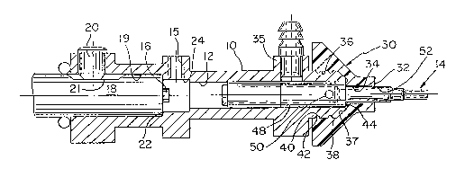
Figure 1 is a side cross~sectional view
of a tool tip assembly for a machine for mounting
surface mount electronic components in one of two
alternate operating conditions, and
Figure 2 is a similar view illustrating
the alternate position.
The tool tip assembly has a housing 10
having an interior bore 12 for receiving an inner
tool tip 14. When this inner tool tip 14 is not in
use, it will be pulled rearwardly by vacuum applied
to a rearward air connection 15 until it stops
against a fixed stop 16 which is part of a pin
member 18. The pin member 18 is axially received
by a second coaxial housing bore 19 and is secured
by a set screw 20. The pin member 18 has an
elongated flat 21 so that the location of the pin
member and hence the stop can be seated against
shoulder 22.
A molded elastomeric outer tool tip 30
having a component engaging surface 32 has a first
bore 34 communicating with this surface and having
a size sufficient to assure that large components
will be picked up when the inner tool tip 14 is
fully retracted against the stop 16 and vacuum is
applied via a forward housing air connection 35. A
second enlarged coaxial bore 36 extending into the
rear of the outer tool tip is located around the
cylindrical end portion 38 of the housing and the
outer tool tip is removably held in place by a pair
of annular housing groves 40 which receive a pair
of annular ridges 42 defined on the inner surface
of this bore 36.
The inner surface of the outer tool tip
flares outwardly 37 from the first bore 34 to the

_ 3 _ 2~5~55~
second bore 36 and an annular, rearwardly facing
bumper 44 is defined at the rear end of the first
bore~ This bumper 44 functions as the forward stop
for the inner tool tip and also functions to
effectively seal the outer tool tip when the inner
tool tip has been pushed forwardly by air under
pressure admitted through the rear air connection
15. To pick up a smaller component on the advanced
inner tool tip 14, vacuum is applied via the
forward connection 35 into the volume 4g
surrounding the inner tool tip and through a
passage 50 in the inner tool tip into an axial bore
52 which communicates with the end of the inner
tool tip.
The inner and outer tool tips can be
quickly replaced by simply pulling the outer tool
tip off of the housing.

Representative Drawing
A single figure which represents the drawing illustrating the invention.
Administrative Status

2024-08-01:As part of the Next Generation Patents (NGP) transition, the Canadian Patents Database (CPD) now contains a more detailed Event History, which replicates the Event Log of our new back-office solution.

Please note that "Inactive:" events refers to events no longer in use in our new back-office solution.

For a clearer understanding of the status of the application/patent presented on this page, the site Disclaimer , as well as the definitions for Patent , Event History , Maintenance Fee  and Payment History  should be consulted.

Event History

Description Date
Inactive: IPC from MCD 2006-03-11
Time Limit for Reversal Expired 1994-05-28
Application Not Reinstated by Deadline 1994-05-28
Deemed Abandoned - Failure to Respond to Maintenance Fee Notice 1993-11-29
Inactive: Adhoc Request Documented 1993-11-29
Application Published (Open to Public Inspection) 1992-05-30

Abandonment History

Abandonment Date Reason Reinstatement Date
1993-11-29
Owners on Record

Note: Records showing the ownership history in alphabetical order.

Current Owners on Record
EMHART INC.
Past Owners on Record
MARK E. ROSSMEISL
RODNEY P. JACKSON
Past Owners that do not appear in the "Owners on Record" listing will appear in other documentation within the application.
Documents

To view selected files, please enter reCAPTCHA code :


To view images, click a link in the Document Description column. To download the documents, select one or more checkboxes in the first column and then click the "Download Selected in PDF format (Zip Archive)" or the "Download Selected as Single PDF" button.

List of published and non-published patent-specific documents on the CPD .

If you have any difficulty accessing content, you can call the Client Service Centre at 1-866-997-1936 or send them an e-mail at CIPO Client Service Centre.


Document
Description 
Date
(yyyy-mm-dd) 
Number of pages   Size of Image (KB) 
Abstract 1992-05-30 1 14
Claims 1992-05-30 1 28
Cover Page 1992-05-30 1 12
Drawings 1992-05-30 1 31
Descriptions 1992-05-30 3 86
Representative drawing 1999-07-08 1 14