Sélection de la langue

Search

Sommaire du brevet 2056559 

Énoncé de désistement de responsabilité concernant l'information provenant de tiers

Une partie des informations de ce site Web a été fournie par des sources externes. Le gouvernement du Canada n'assume aucune responsabilité concernant la précision, l'actualité ou la fiabilité des informations fournies par les sources externes. Les utilisateurs qui désirent employer cette information devraient consulter directement la source des informations. Le contenu fourni par les sources externes n'est pas assujetti aux exigences sur les langues officielles, la protection des renseignements personnels et l'accessibilité.

Disponibilité de l'Abrégé et des Revendications

L'apparition de différences dans le texte et l'image des Revendications et de l'Abrégé dépend du moment auquel le document est publié. Les textes des Revendications et de l'Abrégé sont affichés :

  • lorsque la demande peut être examinée par le public;
  • lorsque le brevet est émis (délivrance).
(12) Demande de brevet: (11) CA 2056559
(54) Titre français: ENSEMBLE DE POINTE D'OUTIL POUR MACHINE DE MONTAGE EN SURFACE
(54) Titre anglais: TOOL TIP ASSEMBLY FOR SURFACE MOUNT MACHINE
Statut: Morte
Données bibliographiques
(51) Classification internationale des brevets (CIB):
  • H05K 3/30 (2006.01)
  • H05K 13/04 (2006.01)
(72) Inventeurs :
  • JACKSON, RODNEY P. (Etats-Unis d'Amérique)
  • ROSSMEISL, MARK E. (Etats-Unis d'Amérique)
  • JACKSON, RODNEY P. (Etats-Unis d'Amérique)
  • ROSSMEISL, MARK E. (Etats-Unis d'Amérique)
(73) Titulaires :
  • JACKSON, RODNEY P. (Non disponible)
  • ROSSMEISL, MARK E. (Non disponible)
  • JACKSON, RODNEY P. (Etats-Unis d'Amérique)
  • ROSSMEISL, MARK E. (Non disponible)
  • EMHART INC. (Etats-Unis d'Amérique)
(71) Demandeurs :
(74) Agent: SWABEY OGILVY RENAULT
(74) Co-agent:
(45) Délivré:
(22) Date de dépôt: 1991-11-28
(41) Mise à la disponibilité du public: 1992-05-30
Licence disponible: S.O.
(25) Langue des documents déposés: Anglais

Traité de coopération en matière de brevets (PCT): Non

(30) Données de priorité de la demande:
Numéro de la demande Pays / territoire Date
620,147 Etats-Unis d'Amérique 1990-11-29

Abrégés

Abrégé anglais


ABSTRACT

TOOL TIP ASSEMBLY FOR SURFACE MOUNT MACHINE
The tool tip assembly has a fixed large
tool tip and a movable telescoping tool tip which
has a smaller area pick-up end. The telescoping
tool tip is displaceable between fixed stops and
the forward stop is defined by an annular bumper
projecting rearwardly from the inner surface of the
fixed tool tip proximate the forward bore portion.
The telescoping tool tip can be quickly and
conveniently accessed for repair, inspection or
replacement by removing the molded elastomeric
fixed large tool tip.

Revendications

Note : Les revendications sont présentées dans la langue officielle dans laquelle elles ont été soumises.


- 4 -
The embodiments of the invention in which an exclusive
property or privilege is claimed are defined as follows:

1. A tool tip assembly for a machine for mounting
electronic components comprising
a fixed tool having coaxial front and
enlarged rear bores,
a housing having a cylindrical forward
portion and a bore extending rearwardly from the
front thereof,
means for removably securing said fixed
tool on said cylindrical housing portion with said
cylindrical forward housing portion in said
enlarged rear tool bore,
a displaceable tool having a rear
cylindrical portion slidably received within said
housing bore and a reduced diameter cylindrical
forward portion,
means for stopping the rearward
displacement of said displaceable tool at a
selected rear position and
said ficed tool including rearwardly
projecting annular bumper means for engaging and
stopping the forward displacement of said rear
cylindrical housing portion of said displaceable
tool at a selected forward position so that when
said fixed tool is removed the displaceable tool
can be removed from said housing.

2. A tool tip assembly for a machine for mounting
electronic components according to claim 1, wherein
said fixed tool is made of elastomeric material.

Description

Note : Les descriptions sont présentées dans la langue officielle dans laquelle elles ont été soumises.

SPECIFICATION 2C`55S59

TOOL TIP ASSEMBLY FOR SURFACE MOUNT MACHINE

The present invention relates to machines
for placing surface mount electronic components on
circuit boards.
In such machines, a tool tip is brought
into engagement with an electronic component to be
placed on a circuit board and a vacuum is applied
to hold the component on the tool tip. Since the
tool tip with the held component may be rapidly
displaced from the pick up location to the deposit
location, the component must be securely held and
this means that larger components should be engaged
by tool tips having larger areas so that a larger
force can be applied. This may be achieved with
the use of a telescoping tool tip which can
alternately present small and large area tool tips
with the inner tool tip being displaceable between
fixed stops to define advanced (pick-up) and
retracted (inactive) positions. These stops have
conventionally been defined within the tool
housing. Repair or replacement required a
disassembly of the tool housing and this was very
time consuming.
It is accordingly an object of the
present invention to provide a telescoping tool tip
which can be quickly accessed for repair or
replacement.
Other objects and advantages of the
present invention will become apparent from the
following portion of this specification and from
the accompanying drawings which illustrates in
accordance with the mandate of the patent statutes
a presently preferred embodiment incorporating the
principles of the invention.


- 2 - 2~555S~

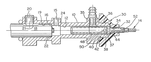
Referring the drawings:
Figure 1 is a side cross~sectional view
of a tool tip assembly for a machine for mounting
surface mount electronic components in one of two
alternate operating conditions, and
Figure 2 is a similar view illustrating
the alternate position.
The tool tip assembly has a housing 10
having an interior bore 12 for receiving an inner
tool tip 14. When this inner tool tip 14 is not in
use, it will be pulled rearwardly by vacuum applied
to a rearward air connection 15 until it stops
against a fixed stop 16 which is part of a pin
member 18. The pin member 18 is axially received
by a second coaxial housing bore 19 and is secured
by a set screw 20. The pin member 18 has an
elongated flat 21 so that the location of the pin
member and hence the stop can be seated against
shoulder 22.
A molded elastomeric outer tool tip 30
having a component engaging surface 32 has a first
bore 34 communicating with this surface and having
a size sufficient to assure that large components
will be picked up when the inner tool tip 14 is
fully retracted against the stop 16 and vacuum is
applied via a forward housing air connection 35. A
second enlarged coaxial bore 36 extending into the
rear of the outer tool tip is located around the
cylindrical end portion 38 of the housing and the
outer tool tip is removably held in place by a pair
of annular housing groves 40 which receive a pair
of annular ridges 42 defined on the inner surface
of this bore 36.
The inner surface of the outer tool tip
flares outwardly 37 from the first bore 34 to the

_ 3 _ 2~5~55~

second bore 36 and an annular, rearwardly facing
bumper 44 is defined at the rear end of the first
bore~ This bumper 44 functions as the forward stop
for the inner tool tip and also functions to
effectively seal the outer tool tip when the inner
tool tip has been pushed forwardly by air under
pressure admitted through the rear air connection
15. To pick up a smaller component on the advanced
inner tool tip 14, vacuum is applied via the
forward connection 35 into the volume 4g
surrounding the inner tool tip and through a
passage 50 in the inner tool tip into an axial bore
52 which communicates with the end of the inner
tool tip.
The inner and outer tool tips can be
quickly replaced by simply pulling the outer tool
tip off of the housing.


Dessin représentatif
Une figure unique qui représente un dessin illustrant l'invention.
États administratifs

Pour une meilleure compréhension de l'état de la demande ou brevet qui figure sur cette page, la rubrique Mise en garde , et les descriptions de Brevet , États administratifs , Taxes périodiques et Historique des paiements devraient être consultées.

États administratifs

Titre Date
Date de délivrance prévu Non disponible
(22) Dépôt 1991-11-28
(41) Mise à la disponibilité du public 1992-05-30
Demande morte 1994-05-28

Historique d'abandonnement

Il n'y a pas d'historique d'abandonnement

Historique des paiements

Type de taxes Anniversaire Échéance Montant payé Date payée
Le dépôt d'une demande de brevet 0,00 $ 1991-11-28
Enregistrement de documents 0,00 $ 1993-04-23
Titulaires au dossier

Les titulaires actuels et antérieures au dossier sont affichés en ordre alphabétique.

Titulaires actuels au dossier
JACKSON, RODNEY P.
ROSSMEISL, MARK E.
JACKSON, RODNEY P.
ROSSMEISL, MARK E.
EMHART INC.
Titulaires antérieures au dossier
S.O.
Les propriétaires antérieurs qui ne figurent pas dans la liste des « Propriétaires au dossier » apparaîtront dans d'autres documents au dossier.
Documents

Pour visionner les fichiers sélectionnés, entrer le code reCAPTCHA :


Pour visualiser une image, cliquer sur un lien dans la colonne description du document. Pour télécharger l'image (les images), cliquer l'une ou plusieurs cases à cocher dans la première colonne et ensuite cliquer sur le bouton "Télécharger sélection en format PDF (archive Zip)" ou le bouton "Télécharger sélection (en un fichier PDF fusionné)".

Liste des documents de brevet publiés et non publiés sur la BDBC .

Si vous avez des difficultés à accéder au contenu, veuillez communiquer avec le Centre de services à la clientèle au 1-866-997-1936, ou envoyer un courriel au Centre de service à la clientèle de l'OPIC.


Description du
Document 
Date
(yyyy-mm-dd) 
Nombre de pages   Taille de l'image (Ko) 
Description 1992-05-30 3 97
Dessins 1992-05-30 1 35
Revendications 1992-05-30 1 32
Abrégé 1992-05-30 1 16
Page couverture 1992-05-30 1 13
Dessins représentatifs 1999-07-08 1 14