Note: Descriptions are shown in the official language in which they were submitted.
2~S6~i73~. -
CROSS REFERENCF, TO ~ EL~TED APPLICATION
This application claims the priority of Ge~nan Applica-
tion No. P 40 39 973~7 filed ~ecember 14, 1990, which is
incorporated herein by reference.
BACKGROUND OF THE INVENTIQN
This invention relates to a device for relieving
tension-loaded servomotors employed for the height adjustment
of cantilever arms, particularly the cantilever arms of open-
pit mining equipment. The apparatus includes at least one
pulling member being connectable in parallel with the
servomotor or servomotors
Cantilever arms of machines such as open-pit mining
equipment, cranes and similar conveying devices often include
; tension-loaded servomotors for height adjustment, particular-
ly hydraulic cylinders. If - for example, in the case of a
malfunction - the servomotor must be replaced, the problem
~- is encountered that before the servomotor can be relieved of
the tension load, the cantilever arm must be fixed in its
position. This is customarily effected by a supporting
framework whlch supports the cantilever arm or, as the case
may be, the heavier counterweight cantilever arm against the
- 2 - :
~s~
ground. It is a disadvantage of such a method that it
requires significant material input, it is time-consuming and
it is not raliable.
Instead of a supporting framework, as outlined above,
additional guying has been emplc,yed by attaching a tension
cable parallel to the servomotor so as to absorb the tensile
forces aftex the servomotor has been relieved of loads. In
order to avoid damage to the hydraulic cylinder, the cable
must be disposed at a sufficient distance from the latter.
Fastening of the cable generally proves difficult because
special and sufficiently stable attachment means, for example
eye straps, are not available or cannot be applied.
Moreover, the cable must also be provided with suitable
attachment means and must have a defined length.
SUMMARY OF THE INVEN~ION
It is an objec$ o~ the invention to provide an apparatus
with which the servomotor can be relieved in the ~hortest
time while simultaneously providing reliable substitute
guying.
This object and others to become apparent as the
specification progresses, are accomplished by the invention,
according to which, briefly stated, the device for relieving
`: - ' , ' : ' ~ ' ~ :, :
~56S~
the servomotor of` the tension loads for an arbitrary period
includes an intermediate member having a first pivot joint
operatively articulated to the cantilever arm for introducing
tension loads, derived from forces acting on the cantilever
arm, into the intermediate mQm~er, a ~econd pivot joint for
being coupled to an end of a tension mPmber attached parallel
to .~he servomotor for the arbitrary period and a third pivot
joint for being releasably coupled to the servomotor. The
first, second and third pivot joints are spaced from one
another and form the three corners of an imaginary triangle.
It is an advantage of the invention that the intar-
mediate member constitutes a simple, inexpensive componant .
which, when not in use, remains disposed on the equipment so
that a removal operation is not needed. Only a single
additional attachment point is required for the pulling
member; such an attachment point may be disposed in the
immediate vicinity of the location of articulation of the
adjustment motor so that no additional supporting structures
are required.
The tension member is preferably a pull rod which is
more easily manipulated than a cable. When not in use, the
pull rod can be brought into a "parked" position, for
example, it mày be folded over in a simple manner.
::
.. .
X~5~;71
While th device according to the invention is suitable
for all types of equipment that are provided with a height-
adjustable cantilever arm, it is primarily intended for
open-pit mining eguipment, such as bucket wheel excavators,
bucket wheel loaders, stackers or the like, and is par-
ticularly suitable for the type of equipment in which the
cantilever arm and the counterbalance cantilever arm are
connected with one another by way o~ a luffing guying
arrangement.
BRIEF DESCRIPTION OF_THE DRAWING
Figures 1 and 2 are schematic elevational views of two
preferred embodiments of the invention.
DESCRIPTION OF THE PREFERRED EMBODIMENTS
,
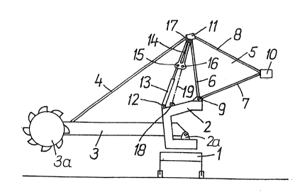
Figures 1 and 2 show a bucket wheel excavator, having a
movable undercarriage 1 on which a C-shaped upper frame 2 is
mounted for pivotal motio~ about a vertical axis. The upper
frame 2 supports a cantilever arm 3 which carries a bucket
wheel 3a at its outer end and which is articulated to the
frame 2 at the joint 2a for the purpose of adjusting its
height. Further, the cantilever arm 3 is connected by pull
_ 5 _
:
-: . . .
.: . , ., , :
: : - ~; .. , : :
: ~ ,, :
~, ~
25)5~
rods 4 (only one shown) with a triangular rocker 5 ~luffing
guying arrangement) composed of an approximately vertical bar
6 and an approximately horizontal bar 7 whose ends are
connectad with one another by pull rods 8 (only one shown).
The rocker 5 is articulated to 'the upper region of the frame
2 for pivotal motion about a horizontal axis 9. A counter-
weight 10 is attached to a free corner of the triangular
rocker 5.
Between a node 11, which is disposed at the upper end of
bar 6 and connects pull rods 4 and 8 with one another, and an
eyelet joint 12 dispo~ed on the upper side of frame 2, a
hydraulic cylinder 13 functioning as a servomotor and an
intermediate member 14 are provided. The latter has pivot
joints 15, 16 and 17 spaced from one another and forming the
corners of an imaginary triangle. The piston rod of the
hydraulic cylinder 13 is çonnected with pivot joint 157 while
the pivot joint 17 is disposed at the node point 11 and
introduces into the intermediate member 14 the loads derived
from forces to which the cantilever arm 3 is exposed. Since
the counterweight cantilever arm formed by rocker 5 and
counterweight 10 is heavier than the bucket wheel cantilever
arm 3 and the hydraulic cylinder 13 is exposed only to
tension loads, the eyelet joint 12 is disposed opposite the
roc~er axis 9 on the side of bucket wheel cantilever arm 3.
~,' ~ ' ,
ZQ5S~71.
Between the eyelet ~oint 12 and the axis 9, immediately
adjoining the eyelet joint 12, a joint 18 is fastened ~o the
upper side of khe frame 2.
In order to prepare for the removal of the hydraulic
cylinder 13, the embodiment according to Figure 1 uses a
cable 19 which is provided with coupling means at both ends
and is attached to joint 1~ on the frame 2 and to pivot joint
16 of intermediate member 14. rrhen the piston rod of the
hydraulic cylinder 13 is extended until the latter is
completely relieved of loads which is the case when the cable
19 has taken over the full load. Depending on the arrange~
ment of the pivot joints of the intermediate mem~er 14, the
joint 18 and the eyelet joint 12 on the frame 2, the inter~
mediate member 14 pivots about the joint 17 in the direction
of the bucket wheel cantilever arm 3 when the cable 19 takes
over the load. The load-free hydraulic cylinder 13 can then
be removed without difficulty, for example by means of a
crane. It is noted that for this operation it is not
necessary to support counterweight 10, for example by means
of a framework (tower) resting on th~ ground, as it has been
the practice in prior art apparatus. The installation o~
the hydraulic cylinder 13 is effected in the reverse se-
~uence; as soon as the cylinder 13 has taken over the load,
.,
, ,
~, :
: ,. , : ~ ~
~:~S6~i7~.
the cable 19 which has functioned as a substitute tension
member, can be removed in a simple manner.
In the embodiment of Figure 2, an intermediate member
14'. is employed in which the space between the upper pivot
joint 17', on the one hand, and the two lower pivot joints 15
and 16, on the other hand, is shorter than in the inter~
mediate member 14 of the previous embodiment, so that the
intermediate member 14' is not directly articulated to the
node 11 but is connected therewith by a pull rod 21. The
substitute tension member is a pull rod ~2 which can he
attached to the joint 18 of the frame 2 and to the Joint 16
of the intermediate member 14'. Removal and installation of
the hydraulic cylinder 13 is effected in the same manner as
in the embodiment described in connection with Figure 1.
The pull rod 22 need not be removed entirely from the
apparatus, it may be folded, for example, about the joint 18
into a detent member 23 disposed on the frame 2 as indicated
by a dash-dot line in Figure 2.
It will be understood that the above description of the
present invention is susc2ptible to various modifications,
changes and adaptations, and the same are intended to be
comprehended within the meaning and range of equivalents of
the appended claims.
:
: ,
: - .
:~ , -. ~ , . :