Note: Descriptions are shown in the official language in which they were submitted.
~691~
MOTION SENSOR BASED ON RAYLEIGH FADED SIGNAL
Field of the Invention
This invention relates to motion sensors or
detectors, and more particularly to motion sensors
which sense motion by relying on the
characteristics of a radio signal.
Background of the Invention
There are many applications in analog or
digital radio communications where it is desirable
to know whether the radio terminal is ~tationary
or moving, and, if it is moving, the approximate
speed. Some conventional techniques of detecting
motion and speed use external devices, such as
sensors on a vehicle speedometer, wheels, or
transmission, which are only useful in permanently
mounted mobile units and are difficult to install.
Other techniques use motion detectors based on
accelerometers mounted inside the radio. These
devices are often too sensitive to be useful since
they may cause false triggering from vibrations
caused by vehicles moving past, or when the
operator types on a keyboard of a mobile data
terminal.
205~91~
Summary of the Invention
This invention relates to a motion sensor
which operates by sensing the fade rate of a
Rayleigh fading radio signal. The fade rate is
proportional to the vehicle speed, so the fade
rate provides an indication of the velocity of the
radio receiving the signal. This approach has
several significant advantages over conventional
0 methods~ in that no external devices or cabling
are required, and the method can be used with a
portable as well as with a vehicle mounted
terminal.
Brief Description of the Drawings
FIG. 1 is a graph which shows the amplitude
of a typical Rayleigh faded signal as a function
of time.
FIG. 2 is a graph showing the level crossing
rate of a signal vs. a reference signal level.
FIG. 3 is a block diagram of a radio adapted
to includ~ a motion detector according to the
invention.
FIG. 4 is a flow chart descri~ing an
algorithm capable of determining motion according
to the invention.
Detailed Description of a Preferred Embodiment
In a cellular telephone or mobile data radio
system a radio signal does not generally follow a
direct path between the mobile or portable unit
and the base station. In most cases there are
multiple reflections of the signal which result in
2 CM00787H
2~691~
Rician or Rayleigh fading. Rician fading refers
to the situation in which there is a strong direct
path component of the received signal, and
Rayleigh fading refers to the situation in which
there is no direct path component. This invention
is particularly useful in those cases where the
radio channel propagation characteristics are
closer to Rayleigh than Rician.
In Rayleigh fading the received radio signal
0 is diminished by periodic fades, the periodicity
being related to the speed that the mobile or
portable unit is moving. FIG. 1 shows the
amplitude of a typical Rayleigh faded signal as a
function of time.
It has been shown (D.O. Reudink, "Properties
of Mobile Radio Propagation above 400 MHz", IEEE
Transac~ions on Vehicular Technology, vol. VT-23,
pp. 143-159, Nov. 1974.) that the level crossing
rate, Nrr which is the expected rate at which a
carrier envelope crosses a specified signal level
R in the positive direction, is given by:
Nr= t2~)1/2 fm ~ exp(_g2)
where Nr= level crossing rate
fm= the maximum Doppler shift
~ = specified signal level R
divided by RMS average signal
level
since fm= ~ = ~ = vf
2~ ~ c
Nr= (2~)1/2 v f ~ exp(~2) where v= velocity
c f= RF frequency
c= speed of light
3 CM00787H
20~691~
FIG. 2 shows the level crossing rate as a
function of the specified received signal level R.
The received signal level R is measured relative
to the RMS average signal level. The maximum
level crossing rate is obtained for a received
signal level R which is 3 dB lower than the RMS
average signal level.
By measuring the level crossing rate, the
velocity of the mobile or portable unit relative
0 to the base station or the source of the received
signal can be calculated:
v= ~_~r ex~ L
(2O 1/2
If the signal level R is set equal to the RMS
average signal level, then ~=1.0, and
v= 2.718 c NL
(2O 1/2f
Since the fre~uency f is known, the level
crossing rate Nr is the only variable on the right
side of the equation. Calculation of the velocity
is simply a matter of multiplying the level
crossing rate Nr by the other values, which are
constant. An error of less than plus or minus 5
dB in measuring the RMS average signal level will
likely produce an error of less than 50% in
measuring vehicle speed, an error level which is
tolerable in a system where it is desired only to
know whether a vehicle or a radio is in motion,
and the actual velocity thereof is not critical.
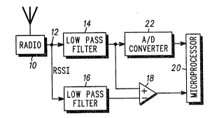
FIG. 3 shows one embodiment of the motion
3~ sensor. A radio 10 provides a Received Signal
Strength Indicator (RSSI) analog output 12, which
4 CM00787H
20~69~
is proportional to the received signal strength
compared to a reference signal level. Since this
i9 proportional to the signal strength, the RMS
average signal level can be calculated by
averaging or low pass filtering this signal,
rather than squaring and averaging as would be the
case if it wexe on a linear scale. An upper low
pass filter 14 has a corner frequency of 2 Hz, and
serves to average the RSSI output to provide an
RMS average signal level. The ~ilter corner
frequency is selected to be longer than one
Rayleigh fade cycle at the slowest speed that the
circuit is designed to operate at, which in this
case is a comfortable walking speed of 3 mph for
an 850 MHz radio.
The lower low pass filter 16 reduces the
bandwidth o~ the Rayleigh faded RSSI signal such
that it can be sampled by a microprocessor without
aliasing. This requires that the low pass filter
16 have a corner frequency less than one-half the
planned sampling rate. The corner frequency o~
this filter must also be higher than the highest
Rayleigh fade rate expected, which is about 68 Hz
for a vehicle travelling at 60 mph and an 850 MHz
radio. A corner frequency of 200 Hz is selected
as being arbitrarily high, which would allow a
corresponding microprocessor sampling rate of ~00
Hz or one sample every 2.5 milliseconds.
The outputs of the two filters are brought
into a comparator 18. The output of the
comparator 18 makes a 0 to 1 transition when the
RSSI signal drops below the RMS average, and a 1
to 0 transition when it rises above the RMS
average. This one bit signal is input to a
microprocessor 20, which counts either 0 to 1
CM00787H
2~569:~
transitions or 1 to 0 transitions, but not both.
The count of transitions in one second is the
level crossing ra~e, from which the velocity can
be calculated.
The RMS average level is also input from the
low pass filter 14 to the microprocessor unit 20
through the A/D converter 22. This RMS average
signal level can be used to assess the li~ely
accuracy of the velocity calculation. This
information would be useful if ~he system were
used to calculate cell handoff information in, for
example~ a cellular telephone system during cell
handoff. The main contributor to error in the
velocity calculation is error in measuring the RMS
average signal level, and the error is more likely
during periods when the RSSI level is fluctuating
wildly. This could occur, for example, when there
is shadowing caused b~ large buildings or other
concrete structures. Short term fluctuations
caused by Rayleigh fading are filtered out by the
low pass filter 14, so if the RMS average signal
level sampled by the microprocessor 20 varies by
no more than 5 dB over a period of several seconds
the accuracy of the velocity calculation is
questionable.
The process described above as implemented
within a microprocessor or digital signa~l
processor is shown in FIG.4 which is a flow chart
describing an algorithm which could be used in
such an implementation. The RSSI is sampled at
30, at a rate of, for example, 400 samples per
second. The samples are filtered at 32 as
previously described, and the filtered samples are
compared to unfiltered samples at 34 where the
z~ro to one transitions are detected. These
6 CM00787H
7 2~91~
transitions are counted at 36, and the velocity of
the radio is calculated at 38.
7 CM00787H