Note: Descriptions are shown in the official language in which they were submitted.
~~~~~'~~~~c
-1-
1 Dual Textured Food Piece Fabrication Apparatus and Method
BACKGROUND
The present invention generally relates to apparatus
and methods for fabricating food products, particularly
to apparatus and methods for fabricating shaped food
products, and more particularly to apparatus and methods
for fabricating shaped, dual textured food products.
The sale of snack-type food products is a highly
competitive business. In addition to the particular food
components, color, flavor, and increasingly shapes and
the play value of such shapes are important in the
marketability of any particular food piece. For example,
fruit-based snack products such as FRUTT CORNER'S' fruit
CA 02057208 2001-O1-19
-2-
1 bit pieces are sold in variously shaped pieces such as
animals, e.g. bears, sharks, and dinosaurs, and objects
such as jets, airplanes, and rockets. while the basic
food formulation from which such shaped, snack food
pieces can remain relatively constant, the novelty and
play value of the shapes in the marketplace decline
rapidly. Consequently, new shapes are constantly being
developed to replace existing shapes as those existing
shapes lose their novelty and appeal.
Accordingly, in the development of apparatus for
fabricating shaped, snack food items, it is imperative
that the molds for forming shaped pieces be inexpensive
to fabricate and replace and easy to install for rapid
change of finished product shapes.
While shaped food pieces are known, such food pieces
are homogeneous in composition and texture. while
desirable, it would be even more desirable to provide a
dual textured, shaped food piece. Recently, dual textured
food compositions and snack food item articles prepared
therefrom have been developed (see U.S. Patent No.
4,847,098, issued July 11, 1989 to J.E. Langler, and U.S.
Patent No. 4,853,236, issued August 1, 1989 to J.E.
Langler, each entitled Dual Textured Food Piece of
Enhanced Stability),
Unfortunately, providing a shaped, dual
textured food piece greatly increases the difficulty of
developing apparatus for fabricating such pieces on an
industrial scale.
Accordingly, it is an object of the present invention
to provide novel apparatus and methods for food products,
which in the preferred form are~shaped, and which in the
most preferred form are also dual textured.
Another object of the invention is to provide molds
which in themselves are inexpensive to fabricate and
which are easy to install and replace. In this regard,
an aim of the invention is to allow replacement of
existing food products shapes as they lose their novelty
~~:~ ~'~~y~?
1 and appeal with new shapes as they are developed.
Yet another object of the invention is to provide
increased speed of operation for maximizing the
fabrication of food products. In this regard, the
cavities are moved along a circuitous path where the
cavities are filled with food material which is allowed
to harden to form the food pieces and where the food
pieces are removed from the cavities before they are
again refilled. Further, in the preferred form, two
cavities are simultaneously filled from a single source
of food material.
Still further, another object of the invention is to
fabricate dual textured food pieces where first and
second food materials are coextruded in a manner where the
first food material is hardened to form an outer shell
portion which encircles and encloses a softer inner core
portion farmed by the second food material.
SUMMARY
Surprisingly, the above objectives can be satisfied
in the field of food fabrication by providing, in the
preferred form, apparatus and methods of food fabrication
where a cavity formed in and defined by abutting inner'
surfaces of first and second plates is moved along a
circuitous path having a first portion where the first
and second plates are abutting together and where the
cavity is filled with food material and with the path
having a second portion where the first and second plates
are spaced from each other allowing the removal of the
hardened food piece from the cavity.
In other aspects of the present invention, apparatus
and methods of simultaneously fabricating first and
second food pieces are provided, where first and second
cavities are cofilled by food material which passes
through and is metered by the intermittent operation of a
pump having first and second inlets in separate fluid
communication with a single source of food material and
having first and second outlets in respective
r ~~ ~'~ >
1 communication with the first and second cavities.
In yet other aspects of the present invention,
apparatus and methods of fabricating dual textured food
pieces are provided, where first food material is
initially extruded to fill the bottom of a cavity, then
the first food material is coextruded with and encircles
a second food material, and finally the first food
material is extruded to fill the top of the cavity.
The present invention will become clearer in light
of the following detailed description of an illustrative
embodiment of this invention described in connection
with the drawings.
DESCRIPTION' OF THE DRAWINGS
The illustrative embodiment may best be described by
reference to the accompanying drawings where:
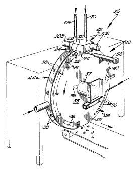
Figure 1 shows a diagramatic, rear perspective view
of an apparatus for fabricating a dual textured food
piece according to the preferred teachings of the present
invention, with the supporting structure being broken
away to expose the internal components of the apparatus.
Figure 2 shows a diagramatic, perspective view of a
food infection manifold according to the preferred
teachings of the present invention which can be utilized
with the apparatus of Figure 1.
Figure 3 shows a partial, enlarged, front perspective
view of the apparatus of Figure 1.
All figures are drawn for ease of explanation of the
basic teachings of the present invention only; the
extensions of the figures with respect to number,
position, relationship, and dimensions of the parts to
form the preferred embodiment will be explained or will
be within the skill of the art after the following
teachings of the present invention have been read and
understood. Further, the exact dimensions and
dimensional proportions to conform to specific forco,
weight, strength, and similar requirements will likewise
be within the skill of the art after the following
CA 02057208 2001-O1-19
-5-
1 teachings of the present invention have been read and
understood.
Where used in the various figures of the drawings,
the same numerals designate the same or similar parts.
Furthermore, when the terms "first", "second", "inner",
"outer", "axial", "radial", and similar terms are used
herein, it should be understood that these terms have
reference only to the structure shown in the drawings as
it would appear to a person viewing the drawings and are
utilized only to facilitate describing the invention.
DESCRIPTION
An apparatus utilizing the present methods for
fabricating a shaped food piece, especially a dual
textured food piece, according to the preferred teachings
of the present invention is shown in the drawings and
generally designated 10.
The shaped food pieces can be homogeneous~in
composition and structure. However, preferred apparatus
embodiments find particular suitability for fabricating
shaped, dual textured fQOd pieces. In a highly preferred
embodiment, the food piece can be of the type described
in U.S. Patent No. 4,847,098, issued July 11, 1989 to
J.E. Langler, and U.S. Patent No. 4,853,236, issued
August 1, 1989 to J.E. Langler, each entitled Dual
Textured Food Piece of Enhanced Stability.
Specifically, the food piece generally includes a first,
solid or "hard" outer shell portion and a second, softer
inner core portion.
Generally, apparatus 10 includes a molding device 18
having a plurality of mold cavities 20 formed in and
defined by first and second mold plates 22 and 24.
Specifically, mold plates 22 and 24 include inner
surfaces 26 which face each other, outer surfaces 28
which are opposite to inner surfaces 26, outer edges 29,
and inner edges 30 opposite to outer edges 29. In the
preferred form, cavities 20 are formed by mold depressions
CA 02057208 2001-O1-19
-6-
1 extending from inner surfaces 26 of plates 22 and 24,
with the peripheries of the depressions being mirror
images at inner surfaces 26 of plates 22 and 24. Material
access channels 32 are provided to cavities 20 such as by
depressions formed in inner surfaces 26 of plates 22 and
24 and extending from cavities 20 outwardly towards and
intersecting with outer edges 29 of plates 22 and 24.
In the preferred form, the peripheries of the depressions
forming channels 32 are mirror images at inner surfaces
26 of plates 22 and 24.
Cavities 20 may have any desired shape such as but
not limited to dinosaurs, sharks, jets, airplanes, or
like novelty shapes. The particular shape of food piece
produced in apparatus 10 may be easily changed by
interchanging plates 22 and 24 having cavities 20 of the
desired shape. Further cavities 20 may be of different
shapes in plates 22 and 24. For example, cavities 20 may
have shapes of differing types of dinosaurs such that
each revolution of plates 22 and 24 create a variety of
shapes of food pieces.
The skilled artisan can appreciate that mold plates
22 and 24 can be fabricated with cavities 20 to provide
finished articles of various shapes. For example, the
shapes can be objects having an identical front and rear,
e.g. a star or disc, or the shape can be more complex,
involving a front and rear which are dissimilar, e.g. a
front view of a bear and a rear view of a bear. In still
another variation, the mold depressions can be mirror
images providing left and right halYes of a complex
shape, e.g. a dinosaur.
Mold cavities 20 are advanced along a continuous,
circuitous path which in the preferred form is generally
in a single plane, especially a vertical plane, and
particularly with inner surfaces 26 of plates~22 and 24
being generally vertical at all~positions along the
circuitous path. Specifically, in the preferred form,
mold plates 22 and 24 are annular and particularly are
U ;,3 ~
1 circular in configuration. Plates 22 and 24 are advanced
along the circuitous path by rotating plates 22 and 24
about the center of the circular shaped configuration.
In the preferred form, circumferentially spaced and
radially extending spokes 34 extend integrally and
contiguously from inner edge 30 of plate 24 and converge
towards and are secured to a shaft 36 located and
extending through the center of the circular
configuration of plate 24 to thus form a wheel-type
arrangement. A solid, circular hub 35 extends integrally
and contiguously from inner edge 30 of plate 22 and is
secured to shaft 36 located and extending through the
center of the circular configuration of plate 22 to thus
form a wheel-type arrangement. The solid configuration
of hub 35 acts as a guard to prevent passage of limbs or
the like through spokes 34 of plate 24 which may abut
against frame or other apparatus components when plates
22 and 24 are rotated. for ease of interchangability of
cavities 20, spokes 34 and hub 35 may be removably
secured to shaft 36 in any suitable manner to allow
removal and replacement of plates 22 arid 24 having
cavities 20 of the desired shape to be fabricated.
likewise, plates 22 and 24 can be formed of two pieces,
with cavities 20 being formed in replaceable and
interchangeable mold portions removably secured to the
remaining portions of plates 22 and 24.
In the preferred form, 60 mold cavities 20 are
provided at equally spaced intervals around plates 22 and
24. Suitable drive means for intermittently rotating
shaft 36 through angles corresponding to the spacing of
cavities 20 may be provided such as by the use of a
stepper motor 37.
Plates 22 and 24 are movable relative to each other
and to shaft 36 between an abutting relation with inner
surfaces 26 abutting to form cavities 20 during a first
portion of the circuitous path and a separated relation
with inner surfaces 26 of plates 22 and 24 spaced from
~ ~~ ~;r '~' ~:~ r
-8-
1 each other during a second portion of the circuitous path.
In the preferred form, plates 22 arid 24, spokes 34,
and/or hub 35 are formed of a flexible material, and in
the highly preferred embodiment are formed of LFXANr"
polycarbonate plastic. It can then be appreciated that
in the highly preferred embodiment, plate 24 moves away
from and is spaced from plate 22 which generally remains
in a single plane, with spokes 34 in the wheel
arrangement for plate 24 providing a greater degree of
flexibility than solid hub 35 utilized for plate 22.
A means far holding plates tat and 24 in an abutting
relation during the first portion of the circuitous path
can be provided such as pairs of rollers 38 located on
opposite sides of plates 22 and 24 for rolling on and
pressing against outer surfaces 28 of plates 22 and 24.
In the preferred form, the first portion of the
circuitous path is defined by 6 sets of rollers 38
provided along about a 155° segment of plates 22 and 24
and particularly from a position intermediate the 12
o~clock and 1 o~clock position to a generally 7 o~clock
position as viewed in Figure 1.
A means for separating plates 22 and 24 during the
second portion of the circuitous path such as a wedge 40
can be provided intermediate inner surfaces 26 of plates
22 and 24 and at a position opposite to the segment
including rollers 38 defining the first portion of the
circuitous path. Wedge 40 in the preferred form flexes
plate 24 away from plate 22 to thus separate inner
surfaces 26 of plates 22 and 24.
In a preferred form, a food material is heated to a
temperature to which the food material is flowable or
pumpable. The pumpable food material is then filled into
cavities 20 generally at the initiation of the first
portion of the circuitous path such as by an injection
manifold 42, with the food material cooling and hardening
in cavities 20 as they advance along 'the circuitous path.
Tn the preferred form, food injection manifold 42
~' 1 ,! I~)
~~ ~a
_g_
1 simultaneously fills two cavities 20 located on the
opposite sides of the 12 o'clock position for increased
speed of operation. Further, in the preferred form, food
injection manifold 42 cofills or coextrudes cavities 20
with first and second food materials to form dual
textured food pieces, Of course, in other useful
embodiments, the present apparatus can be equipped with a
food injection manifold which delivers only a single
fluid food material such as in the preparation of a
homogeneously textured food product. The preferred form
of food injection manifold 42 will be set forth in more
detail after the operation and features of molding device
18 have been explained.
In the most preferred form and in addition to rollers
38, the plate holding means may include means for
exerting extra pressure against plates 22 and 24 opposite
to and as cavities 20 are being filled to counteract any
pressures created by the food material filling cavities
and to maintain plates 22 and 24 in an abutting
20 relation at that point. Particularly, a stationary
backing or anvil jaw 52 is arranged parallel to and
generally abutting with outer surface 28 of plate 24. A
complementary, movable jaw 54 is arranged parallel to
outer surface 28 of plate 22 and opposite to jaw 52.
Suitable means such as an air cylinder 56 is provided for
moving jaw 54 between a first position and a second
position. In the first position, jaw 54 is spaced from
plate 22 such that plates 22 and 24 are freely rotatable
past and between jaws 52 and 54. In the second position,
jaw 54 abuts with and presses against plate 22 and thus
sandwiches and clamps plates 22 and 24 intermediate jaws
52 and 54. With jaw 54 in its second position, cavities
20 may be filled in plates 22 and 24 with further
assurance that the force exerted by the food material
filling cavities 20 does not separate inner surfaces 26
of plates 22 and 24. Jaws 52 and 54 have a shape
complementary to plates 22 and 24 and a size to abut on
6 5, ~, t s~ ~! fY~
_10_
1 plates 22 and 24 a distance to extend over cavities 20
being filled by food injection manifold 42.
In a more preferred embodiment, the apparatus is
provided with a means for cooling the filled cavities 20.
This means for cooling provided assists cooling the
heated food material in cavities 20 for hardening
therein. In the preferred form, an air manifold 44
operatively connected to a pressurized, cool air supply
(not shown) passes cooled, pressurized air over outer
surfaces 28 of plates 22 and 24 opposite cavities 20
after cavities 20 have been filled by injection manifold
42 and at least during the first portion of the
continuous path. In the most preferred form, air
manifold 44 includes a plurality of openings 46
circumferentially spaced at locations and distances
corresponding to the circumferential spacing of cavities
of plates 22 and 24 for directing cooled, pressurized
air generally perpendicularly towards outer surfaces 28
of plates 22 arid 24 opposite cavities 20.
20 The food material is cooled in cavities 20 by air
manifold 44 during the first portion of the circuitous
path to form the hardened food piece having the shape of
cavities 20. During the second portion of the circuitous
path, plates 22 and 24 are separated such as by wedge 40.
In the preferred form with cavities 20 formed by
depressions in both plates 22 and 24, the hardened food
piece extends beyond inner surfaces 26 of plates 22 and
24. Further, in the preferred form with plates 22 and 24
being generally vertical, food pieces will fall by
gravity out of the depressions in plates 22 and 24
forming cavities 20 as plates 22 and 24 are separated,
with gravitational forces placing the food piece under
torsional force for tipping out of the mold depressions in
plates 22 and 24. When plates 22 and 24 have separated a
distance generally equal to the size of the food piece,
the food piece will fall from between plates 22 and 24 of
molding device 18 such as onto a conveyor as shown for
~~~~r~'~.~~r
-11-
1 further processing such as packaging.
Depending upon the particular food material utilized
to make the food piece, the food piece may have a sticky
or adhesive force to adhere and remain in one of the
depressions forming cavity 20 and which is sufficient to
resist the food piece from falling therefrom by gravity.
Tn those cases, molding device 18 should include a means
for removing any food piece which rernains in cavities 20
when plates 22 and 24 are separated in the second portion
of the circuitous path and prior to reentry in the first
portion of the circuitous path. In the most preferred
form, an arcuate, piccolo tube 48 can be provided
intermediate inner surfaces 26 of plates 22 and 24 when
separated, generally parallel to inner edges 30 of plates
22 and 24, and radially inward of cavities 20. Tube 48
can be operatively connected to a source of pressurized
air whether or not cooled but conveniently to the same
coal air supply which supplies air manifold 42 such as by
an inlet extending radially outwardly from tube 48 and
intermediate inner surfaces 26 of plates 22 and 24. Tube
48 directs the moving, pressurized air radially outwardly
and toward cavities 20 for blowing out any food pieces
remaining in cavities 20. In the mast preferred form,
tube 48 includes a plurality of openings 50
circumferentially spaced at locations and distances
corresponding to the circumferential spacing of cavities
20 of plates 22 and 24.
Suitable provisions can be included to prevent food
infection manifold 42 from attempting to fill a cavity 20
in which a food piece remains. For example, with plates
22 and 24 formed of transluent material, a photodetector
maybe utilized to detect a nontranslucent food piece
within cavity 20 and to prevent actuation of food
infection manifold 42 far cavity 20 in which the food
piece is detected.
For purposes of describing the operation of apparatus
10, a particular pair of cavities 20 will be followed
~~~C,~~~~.~i:~
-12-
1 along the continuous, circuitous path. In particular,
the pair of cavities 20 will be assumed to be initially
positioned in the first portion of the circuitous path
and intermediate the first two sets of rollers 38 of the
first portion of the circuitous path and below food
injection manifold 42. Air cylinder 56 moves jaw 54 from
its first position to its second position to sandwich
plates 22 and 24 between jaws 52 and 54, While sandwiched
between jaws 52 and 54, food injection manifold 42 fills
the pair of cavities 20 with heated, pumpable food
material. After the filling step has been completed, air
cylinder 56 moves jaw 54 from its second position to its
first position to space jaw 54 from plate 22, and shaft
36 is rotated 12° in the preferred form. The 12°
rotation of shaft 36 moves plates 22 and 24 and the pair
of cavities 20 from beneath food injection manifold 42
and in front of openings 46 of air manifold 44 where
cooling air is directed toward outer surfaces 28 of
plates 22 and 24 while the following pair of cavities 20
are being filled with the food material by food injection
manifold 42. When the following pair of cavities 20 have
been filled with food material, shaft 36 is again rotated
12° in the preferred form moving the pair of cavities 20
to the next pair of openings 46 of air manifold 44 thus
permitting the succeeding pair of cavities 20 to be
filled. This procedure is repeated until the pair of
cavities 20 pass the last set of rollers 38 of the first
portion of the circuitous path. At that time plates 22
and 24 enter the second portion of the circuitous path
and begin to separate under the action of wedge 40. As
the pair of cavities 20 continue to move at 12° intervals
along the second portion of the circuitous path, surfaces
26 of plates 22 and 24 will be spaced a distance
sufficient to allow the now cooled and hardened food
piece to fall by gravity from cavities 20 between the
vertically arranged, inner surfaces 26 of plates 22 and
24. As the pair of cavities 20 continue to move at 12°
~~ !.~ '~ k ~4 r~J
-13-
intervals along the second portion of the circuitous
path, the pair of cavities 20 will be positioned radially
outwardly of tube 48 where air from openings 50 will blow
out any food pieces which remain in cavities 20 and which
will also fall under gravitational forces from between
the vertically arranged, inner surfaces 26 of plates 22
and 24. The pair of cavities 20 continue to move at 12°
intervals along the second portion of the circuitous path
toward the first portion of the circuitous path where
plates 22 and 24 are again pressed into an abutting
relation by the first set of rollers 38. When the pair
of cavities 20 have been rotated through 30 intervals of
12°, i.e. one complete revolution, the pair of cavities
will be again positioned below food injection manifold
15 42 where the process may be repeated.
In the preferred form, two complete revolutions of
plates 22 and 24 are made per minute such that 120 food
pieces are fabricated per minute. It can then be
appreciated that molding device 18 according to the
20 teachings of the present invention allows food pieces to
be economically mass produced in shapes.
Although wedge 40 is shown as the means for
separating plates 22 and 24, other types and forms of
means for separating plates 22 and 24 can be utilized
according to the teachings of the present invention. For
example, pins can be provided slideably mounted in one of
plates 22 and 24 for abutment with the other of plates 22
and 24, with the pins being slid by caroming on a
stationary cam provided adjacent to plates 22 and 24 in
the second portion of the circuitous path.
Tn the most preferred form, food injection manifold
42 coextrudes first and second food materials to form a
dual textured food piece. Specifically, 'the first food
material which forms the outer shell is initially
extruded into cavity 20 to fill the bottom of cavity 20,
the first and second food materials are then coextruded,
with the first food material being extruded to encircle
,~ r.r
-14-
1 the second food material, and then the first food
material is finally extruded into cavity 20 to fill the
top of cavity 20. It can then be appreciated that the
second food material is then totally enclosed by the
first food material. When the first food material
hardens, the fj_rst food material forms an outer shell
portion enclosing the second food material forming an
inner core portion. In the most preferred form, the
second food material comprises approximately 10-30~ of
the food piece by weight, with the first food material
comprising approximately 70-90~ of the food piece by
weight. Further, in the preferred form, the first food
material is provided to food injection manifold 42 heated
to a temperature in the order of 150--180°F (66-82°C)
whereas the second food material is provided to food
injection manifold 42 at a temperature range in the order
of 50°F (10°C) to room temperature.
Figure 2 shows a diagrammatic view of the most
preferred form of food injection manifold 42 which can be
utilized with molding device 18 according to the teachings
of the present invention to form such a dual-textured
food piece. Food injection manifold 42 generally
includes first and second bores 60 and 62 which are
circumferentially spaced and radially arranged to be
diametrically aligned with plates 22 and 24 and
specifically to be in fluid communication with access
channels 32 of two, adjacent cavities 20. Hollow
injection pins 64 and 66 in the form of hollow tubes are
located concentrically within bores 60 Gnd 62 and as such
are also in fluid communication with access channels 32
through bores 60 and 62. A single inlet 68 is provided
as a source of and for receiving the first food material
under pressure. Similarly, a single inlet 70 is provided
as a source of and for receiving the second food material,
with the second food material being fed by gravity or
under pressure.
Food injection manifold 42 further includes means for
~~~ ~~~s'~~.jr's
-15-
1 intermittently supplying bores 60 and 62 and injection
pins 64 and 66 with the desired amount of food material
from inlets 68 and 70 respectively. In the most
preferred form, first and second food pumps 72 and 74 are
provided, with each pump 72 and 74 having two inlets 76
and 78 and two outlets 80 and 82. Particularly, first
and second conduits 84 and 86 are provided having first
ends in fluid communication with inlet 68 and having
opposite ends in fluid communication with inlets 76 and
78 of pump 72. A conduit 88 extends from outlet 80 of
pump 72 to bore 60 and a conduit 90 extends from outlet
82 of pump 72 to bore 62. Further, first and second
conduits 92 and 94 are provided having first ends in
fluid communication with inlet 70 and having opposite
ends in fluid communication with inlets 76 and 78 of pump
74. A conduit 96 extends from outlet 80 of pump 74 to
injection pin 64 and a conduit 98 extends from outlet 82
of pump 74 to injection pin 66.
In the most preferred form, pumps 72 and 74 are of
the gear type and particularly are zENITH'"~ dual outlet
pumps. specifically, pumps 72 and 74 include a first
gear-like member 102 in gearing relation with a second
gear-like member 104 in turn in gearing relation with a
third gear-like member 106. In the preferred form, gear-
like members 102, 104, and 106 are of the same diameter
and length, with their rotational axes lying in a single
plane. It can then be appreciated that due to the
gearing relation, gear like members 102 and 106 rotate in
the same direction while gear-like member 104 rotates in
the opposite direction of gear-like members 102 and 106.
Outlets 80 and 82 lie on the mating side of gear-like
members 102 and 104 and of gear-like members 104 and 106
while inlets 76 and 78 lie on the exit side of gear-like
members 102 and 104 and of gear-like members 104 and 106.
Thus, inlet 76 lies on the opposite, axial side of outlet
80 and of inlet 78, with outlet 82 lying on the opposite,
axial side of inlet 78 and of outlet 80. One or more of
l~~'~~;~<~~%
-16-
1 the gear-like members 106 of pumps 72 arid 74 may be
driven in an intermittant manner by any suitable manner
such as by motor 108.
In operation of pumps 72 and 74, food material
entering inlets 76 of pumps 72 and 74 must flow around
the circumference of gear-like members 102 to outlet 80
or along the circumference of gear-like members 104 to
outlet 82. Similarly, food material entering inlets 78
of pumps 72 and 74 must flow around the circumference of
ZO gear-like members 106 to outlet 82 or along the
circumference of gear-like members 104 to outlet 80.
Although pumps 72 and 74 are capable of pumping the food
material, pumps 72 and 74 are utilized in a metering or
valve mode as the food material is pressurized up to
about 200 to 350 psi in inlets 68 and 70 in the most
preferred form. Specifically, by rotating gear-like
members 102, 104, and 106, passage of food material is
allowed from inlets 76 and 78 to outlets 80 and 82 of
pumps 72 and 74. Conversely, when gear-like members 102,
104, and 106 are stationary, passage of food material is
prevented from inlets 76 and 78 to outlets 80 and 82 of
pumps 72 and 74.
In operation of food injection manifold 42 with
molding device 18, after plates 22 and 24 have been
rotated into position with cavities 20 in alignment with
bores 60 and 62 and injection pins 64 and 66, pumps 72
and 74 are intermittently operated to allow passage of
the tood material from inlets 68 and 70 to cavities 20.
Specifically, motor 108 of pump 72 is actuated allowing
the first food material to flow from inlet 68 through
conduits 84 and 86 into inlets 76 and 7B of pump 72 and
through outlets 80 arid 82 of pump 72 through conduits 88
and 90 into bores 60 and 62 and into the aligned cavities
20. After the bottom of cavities 20 are filled with the
desired amount of first food material, motor 108 of pump
74 is simultaneously actuated allowing the second food
material to flow from inlet 70 through conduits 92 and 94
~~~~~~~~~t~
-17-
1 into inlets 76 and 78 of pump 74 and through outlets 80
and 82 of pump 74 through conduits 96 and 98 into
injection pins 64 and 66 to then be coextruded into
cavities 20 with the first food material flowing into
cavities 20 through bores 60 and 62. After the desired
amount of first and second food materials has been
coextruded into cavities 20, actuation of motor 108 of
pump 74 is stopped to thus stop pump 74 and prevent
passage of the second food material from inlet 70 to
injection pins 64 and 66 through pump 74. Pump 72 is
continued to be operated to fill cavities 20 and encircle
the second food material. when the desired amount of
first food material has passed to fill cavities 20,
actuation of motor 108 of pump 72 is also stopped to thus
stop pump 72 and prevent. passage of the food material
from inlet 68 to bores 60 and 62 through pump 72. At
that time, plates 22 and 24 may be rotated into the next
position with the next pair of cavities 20 in alignment
with bores 60 and 62 and injection pins 64 and 66, and
the process may be repeated.
rt can be appreciated that food injection manifold 42
ensures that the appropriate amounts of food material are
metered at the appropriate times. Undesirable amounts or
timing of food material may result in defective products
such as but not limited to the possibility of
insufficient thickness of the outer shell portion to
contain the inner core portion. Similarly, it can be
appreciated that the annular space between the inside
diameters of bores 60 and 62 and the outside diameters of
injection pins 64 and 66 and that the spacing of the
lower ends of injection pins 64 and 66 from the lower
ends of bores 60 and 62 or in other words cavities 20 of
molding device 18 be sufficient to ensure the outer shell
portion has sufficient thickness to contain the innar
core portion. Furthermore, it can b~ appreciated 'that
food injection manifold 42 ensures that the food material
is divided from a single source to two, separate
..,
~~d;~'~;~jJ~~
-is-
1 cavities. Thus, food infection manifold 42 allows
increased speed of operation without requiring multiple
feeding systems.
Thus since the invention disclosed herein may be
embodied in other specific forms without departing from
the spirit or general characteristics thereof, some of
which forms have been indicated, the embodiments
described herein are to be considered in all respects
illustrative and not restrictive. The scope of the
invention is to be indicated by the appended claims,
rather than by the foregoing description, and all changes
which come within the meaning and range of equivalency of
the claims are intended to be embraced therein.
what is claimed is: