Note: Descriptions are shown in the official language in which they were submitted.
2~S7~3
TELECOMMUNICATIONS CABLE
This invention relates to a telecommunications
cable.
In present telecommunication cable designs,
ripcords are incorporated beneath metal sheaths for the
purpose of opening the sheaths thereby giving access to the
cable cores. Problems are associated with obtaining access
to the ripcords by any present method before the sheaths
may be opened, and these methods include distortion of the
lo telecommunications cable by a bending operation to render
the ripcord available at a particular location. By way of
example, in the case of an optical cable it is necessary as
part of the ripcord access procedure to bend the cable at a
chosen location to expose the ripcord at a cut which has
been previously provided around the cable jacket and
through the sheath. A sharp extraction tool is then
required to pass beneath the ripcord and to withdraw it
outwardly through the cut.
In the case of all optical cables incorporating
ripcords, there is thus a problem in obt~;n;ng access to
ripcords. Further to this, in the case of optical cable,
bending of a cable may result in undue bending or even
p;nrh;ng of fibers thereby increasing attenuation and fiber
breakage. Additionally, where the optical cable structure
includes tubes housing fibers, the tubes may become damaged
because of such bending procedures. Also, the use of a
sharp extraction tool may result in damage to parts of a
cable core, i.e. in the case of optical cables, damage to
the optical tubes or fibers.
The present invention seeks to provide a
telec- ;cations cable, particularly an op~ical cable,
which will negate or minimize the above problems.
Accordingly, the present invention provides a
telecommunications cable comprising a core including
elongate transmission elements, a she~th extending around
the core, the sheath having overlapped edge regions
extending longitudinally of the cable, an elastomeric
2~7~3
jacket surrounding the sheath, and at least one ripcord,
the ripcord extending longitudinally along the cable and
alternating between lengths of the ripcord which are
disposed radially within the sheath and lengths of the
ripcord disposed radially outside the sheath, the ripcord
extending between the overlapped edge regions as it
alternates between positions inside and outside the sheath.
More particularly, the present invention includes
an optical cable having a core which includes at least one
lo optical fiber extending longitudinally along the core, the
sheath extending around the core with overlapped edge
regions, an elastomeric jacket and a ripcord, the ripcord
being disposed radially within the sheath and then outside
the sheath in alternating fashion as defined in the last
lS preceding paragraph.
The invention also includes a method of making a
telecommunications cable comprising moving a cable core
along a passline while simultaneously wrapping a sheath
around the core with longitudinally extending edge regions
of the sheath overlapping one over the other, and
positioning a ripcord longitu~;n~lly of the core, the
ripcord alternating between lengths of ripcord which lie
radially within the sheath and lengths of ripcord which are
disposed radially outside the sheath, the ripcord extending
between the overlapped edge regions as it alternates
between positions inside and outside the sheath.
As may be seen from the above telecommunications
cable construction and which may be prepared by the method
of the invention, while the ripcord is necessarily
positioned inside the sheath for the purpose of opening the
sheath to gain access to the cable core, nevertheless the
ripcord also lies outside the sheath along specific lengths
of cable so as to be accessible, after cutting through the
cable jacket, without first having to sever through the
sheath and bending the cable to expose a length of the
ripcord.
In a practical construction, a length of cable
2~7~3
jacket may be removed to obtain access to a length of
:ripcord which extends outside of the sheath, thereby
obtaining access to the ripcord which then may be easily
used for the purpose of ripping open the sheath.
One embodiment of the invention will now be
described by way of example, with reference to the
accompanying drawings, ln which:-
Figure 1 is a lateral cross-sectional view through
an optical cable according to the embodiment;
0 Figure 2 is a partially diagrammatic isometric
view of the cable of Figure 1 with the cable jacket
omitted;
Figure 3 is a view similar to Figure 2 but
including the jacket; and
Figure 4 shows part of the cable during
manufacture to illustrate one stage in the manufacture of
cable.
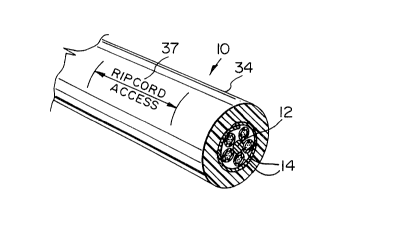
As shown in Figure 1, an optical cable 10 of the
embodiment comprises a cable core consisting of a central
longitudinally extending tensile strength member 12
surrounded by a plurality, namely five, tubes 14 which
extend longitudinally of the core while being wrapped
helically around the strength member 12 either in a single
direction or in alternating directions. In the drawings
the tubes are shown spaced apart for clarity. However, in
practice it would normally be expected for the tubes to
contact each other. Within each tube are enclosed a
plurality of optical fibers 16. As may be seen from Figure
1 and particularly from Figure 2, the cable includes a
corrugated steel sheath 18 and two ripcords 19 and 20. As
may be seen from Figure 2, each of the ripcords 19 and 20
alternates longitudinally of the cable from lengths of
ripcord which lie radially within the sheath to lengths of
ripcord which lie radially outside the sheath. Each
ripcord alternates between its lengths inside and outside
of the sheath by the ripcord passing around an edge of the
sheath. More particularly, the ripcord 20 has lengths 22
2~s7l~3
which lie outside the sheath and lengths 24 which lie
inside the sheath with these lengths being connected
together by the ripcord extending around one longitudinal
edge region 26 of the sheath. In contrast, the ripcord 19
extends around the opposite edge region 28 of the sheath to
have lengths 30 on the outside of the sheath and lengths 32
inside the sheath. The two ripcords are applied so that
each length 22 of the ripcord 20 is in phase with a length
30 of the ripcord 19 along the same length of cable and the
lo length 30 is shorter than the length 22 so as to avoid
crossing of the ripcords one over the other as they extend
along the cable. This is clear from Figure 2. Surrounding
the cable sheath is a polyethylene jacket 34 formed by
normal extrusion techniques.
During manufacture, a printed designation is
preferably added at intervals along the outside of the
cable jacket for instance as shown at 37 by Figure 3, to
indicate to an installer of cable positions of the lengths
22 and 30 of the two ripcords. The ripcord access
designation may for instance be as shown by Figure 3 or by
any other acceptable designation provided by the cable
manufacturer.
As may be seen from the above embodiment, it is
totally unnecessary to bend the cable to obtain access to
the ripcords or to use sharp tools for ripcord extraction
and which could cause damage to parts of the cable core.
With the embodiment of the present invention, the installer
merely needs to remove a length of cable jacket in the
designated region for instance as shown by Figure 3, to
expose outer lengths 22 and 30 of the two ripcords. Each
ripcord may then be severed along the length 22 or 30 to
provide the installer with two ripcord ends on each
ripcord. The two ripcords may then be pulled in the
appL~Liate direction to tear through the steel sheath 18,
and the jacket 34 for a length along the cable sufficient
to expose the core for installation purposes. As may be
seen therefore, as the cable is not bent for access to
2~7~53
ripcords and a cutting tool does not pass through the
sheath, no damage is caused to elements within the core
during exposure of or use of the ripcords.
The ripcords are easily placed in position during
cable manufacture. Before the sheath 18 is wrapped around
the core, it is formed into corrugated form while still in
the form of a flat strip 38 as shown by Figure 4. Each of
the ripcords 19 and 20 is guided first along one surface
of the corrugated strip 38 and then along the other in
lo alternating fashion with each ripcord extending around the
appropriate edge of the strip. An adhesive is used to
apply the ripcords to the peaks of the corrugations as the
ripcords extend across them. Hence the ripcords are held
in the desired positions during the wrapping operation of
the sheath which is to follow. The strip 38 of sheath
material is coated on both sides with a plastics material
which softens during the extrusion process of the jacket so
as to bond the jacket to the sheath. Further to this the
coated material on the sheath fuses between the overlapping
edge regions by the heat provided by the extrusion process
so as to seal together the overlapped edge regions of the
sheath. Hence the two ripcords 19 and 20 in passing
between the overlapped edge regions of the sheath become
embedded in the fused coating material.
It is of course not essential for a cable to have
two ripcords 36 as described in the embodiment. In a
modification (not shown), a cable structure is provided
with one ripcord.
As may be seen from the embodiment, the sheath
cannot be torn continuously along its length by either of
the ripcords 19 and 20, because these lie outside the
sheath in the ripcord access regions. In a modification
(not shown), to enable the sheath 18 to be torn
continuously along its length, another ripcord is included
within the cable, this other ripcord lying entirely
radially within the sheath and being accessible by opening
the sheath with either or both of the ripcords 19 and 20.