Note: Descriptions are shown in the official language in which they were submitted.
~C'~'~!~f
Background of the Invention
Field of the Invention
This invention relates to a device that measures the weak magnetic fields,
both space and time dependent, which are generated by a souxce inside an
object to be investigated. Such instruments are employed to detect magnetic
fields elicited especially by the neural functions; the method is gaining grad-
ually a more important role in medical diagnostics and research. In particu-
lar, it is possible to investigate the brain functions and disorders in a
human
being without touching the person or exposing him to electromagnetic radi-
atian or radioactive tracers. In contrast to the widely used electroencephalo-
gram (EEG), in which the electric potential distribution is measured on the
surface of the scalp, the magnetoencephalogram suffers far less from distor-
tions caused by inhomogeneities in the conductivity of the human tissue.
Therefore, it is possible to locate source currents related to brain activity
with a spatial and temporal resolution of a few millimeters and millisec-
onds. The method has been reviewed in detail, for example, in CRC Critical
Reviews in Biomedical Engineering, volume 14 (1986), issue 2, pp. 93-126.
Instruments used in MEG should be able to detect magnetic signals whose
magnetic flux density is typically 100 fT or less. In addition, the measure-
ment is to be performed simultaneously at several locations; the measure-
ment of even more than one hundred magnetic signals from all over the
head is necessary. The only sensor capable of detecting these minute signals
is the so-called Superconducting Quantum Intexference Device (SQL3ID)
magnetometer. The operation of the device has been explained in detail in
an axtiele in Journal of Low Temperature Physics, volume 76 (1989), issue 5/6,
pp. 287-386. The device requires a low operating temperature. Commonly, it
is in a liquid helium bath inside a vacuum-insulated dewar vessel; the tem-
perature is then 9:.2 K.
This invention focuses especially an the insert inside the dewar vessel; the
SQUID magnetometer elements are attached to this insert. The insert must
be stable enough and it must withstand tensions and changes in dimensions
caused by the differential thermal contraction of , various materials while
cooling the device dowr, to its operating temperature. At the same time, also
the heat leak from room temperature to the helium bath must be mini-
mized. The latter fact is of particular importance, because the device in-
3 ~t''~'~~~~
tended for measurements on a wide area necessarily has a large cross-sec-
lion. The neck of the dewar needed for such a device must be wide; thus the
heat leak by conduction, convection and radiation through the neck can
substantially increase the helium boil-off rate and thus shorten the duty cy-
cte between maintenance operations.
Description of the Related Art
A well-known prior-art structure of an insert (see, e.g. Review of Scientific
Instruments, vol. 58 (1987), issue 11, pp. 2145-2156) consists of a fiber
glass tube
body, to which the metallic radiation shield baffles are attached in the neck
region. In the lower end of the tube there is a holder to which the individ-
ual magnetometers or gradiorneters are attached. All magnetometers or gra-
diometers can be on a same substrate as well, as has been presented in
EP 111 827. The latter solution has, however, the drawback that all sensors
must be in a common plane; thus it is not possible to adapt the device to the
shape of the person to be investigated, as is possible when using individual
sensor elements.
The electronic components which must be kept at liquid helium tempera-
tore are soldered on a printed circuit board attached to the tube body, and
the
wirings from the top plate connectors at room temperature are routed to
liquid helium space inside copper-nickel tubes. The structure has, however,
several drawbacks. The whole unit consists of one single component which
is tedious and expensive to assemble and maintain. Especially in dewar ves-
sels with wide-area necks a large space is left between the radiation baffles;
the heat convects partially between two baffles because of the turbulence of
the outflawizlg helium gas. Therefore, the temperature distribution tends to
equalize in the vertical direction, increasing the boil-off rate
unnecessarily.
A neck plug made of foam plastic, attached to the tube body, lzas also been
employed to circumvent the latter probtem.
In another kzzow solution (see DE 3 515 199) the body of the magnetometer
has been divided into two parts. The so-called flux transformer coils of the
magnetometer are in a fixed holder an the bottom of the dewar; this holder
is then connected, via a mufti-contact supercanducting connector to a mod-
ule that contains a group of SQUIDS, all inside 1 single element, a neck part
and an electronics unit. The neck part contains all the necessary cabling and
the thermal radiation shields; the electronics unit forms also the top plate
for the dewar. In this construction, the balder with the flux transformers
has been assembled already during the fabrication of the dewar vessel and
can not be removed from the dewar via the neck made small to minimize
the heat leak. As drawbacks one may mention that it is impossible to change
or repair the flux transformers afterwards and that it is very difficult to
make reliable mufti-contact superconducting connectors. One may note that
although the need for such connectors has existed, in different circum-
stances, already for twenty years no such connectors have been made in
practice. The gradiorneter holder has been fixed firmly and rigidly to the de-
war bottom; in addition the module with the SQUID group, the neck plug,
and the electronics unit is of rigid construction (column 4, lines 2-10).
Therefore, when cooling the device down to ifs operating temperature, dan-
gerously large tensions arid stresses may be generated because of differential
thermal contraction of various materials; these stresses may break the struc-
ture.
The radiation shields in the neck have in DE 3 515 199 been realized in an
conventional way (see Fig. 4). Then, the convection problem between two
successive baffles occurs. In addition, the module containing the SQUID
group, the neck with cables and the electronics unit form a single piece
which is difficult to disassemble for eventual maintenance. Furthermore,
the referred publications do not present any solution to the problem that
arises when there are very many channels, on the order of 100: the cabling
in the neck easily dominates the heat leak. This problem can be circum
vented by choosing the conductor material to be very resistive, but then, the
noise of the sensors will increase in intolerably if conventional read-out
methods are used.
The DE 3 515199 also discusses the possibility of making the cabling by pat-
terning a flexible printed circuit board. This solution, although very elegant
and efficient in the manufacturing point of view, has a drawback: the con-
ductor materials on standard printed circuit boards have high conductance
and a resistive material to reduce heat leak cannot be chosen freely. It is
also
impossible to twist the wires to increase the immunity to interference mag-
netic fields and cross-talk between the channels.
DE 3 515 237 deals with a similar array of gradiometers as DE 3 515199; in
particular, the SQUID group, which has been integrated as a single module
on a common substrate, and its internal structure are discussed. Specific at-
tention is paid to the arrangement of wirings via groundplanes and to the
5
magnetic shielding of the SQUIDs by means of superconducting loops and
groundplanes. In this aforementioned application, the SQUID chip has been
attached to a printed circuit board, onto which the conductors have been pat-
terned. Also, the electronics unit forms the top plate of the dewar vessel
(see
Fig. 1}. Furthermore, the assembly of flux transformers and the SQUID
group have been connected in a way that can be easily disconnected, for ex-
ample via a mufti-contact superconducting connector. The drawbacks of this
construction are mainly the same as in the first referred publication. In par-
ticular, the problems are enhanced when the number of channels in large,
on the order of one hundred of more. A complete modularity that is neces-
sary for reliability, easy testability and ease of manufacture is not reached,
completely reliable superconducting multicontact connectors are difficult if
not impossible to manufacture, and if one SQUID fails, the complete group
of SQUIDS has to me changed. In addition, the heat leak problem has not
been solved by the conventional wiring and radiation shield structures uti-
lized in the referred publication. Neither has the differential thermal con-
traction been taken into account.
FP 3b1 137 discusses a magnetometer that can be positioned in an unconven-
tional way, upside down so that the gradiometer coils are topmost. Liquid
helium is inside a separate vessel inside the dewar; the cold helium gas boil-
ing off this inner vessel is led, via tubes; to cool the gradiometer coils.
The
SQUID group is inside a separate unit in the liquid helium container. The
neck of the dewar is substantially narrower than the gradiometer part; thus,
most parts have to be assembled in place when the dewar is being made. To
prevent counterflow of warm helium gas from outside to inside, a special
constriction with relief flaps has been constructed in the neck. The basic
idea
of this device is significantly different from what is aimed at in our inven-
tion; thus, for example the neck is of completely different structure, and the
whole structure is not modular in the sense what would be desired. When
3p the number of channels approaches one hundred, it is reasonable to assume
that an even and reliable cooling of the gradiometer coils cannot be accom-
pushed with a moderate liquid helium consumption. To maintain such an
Instrument with many fixed parts inside the dewar would also be difficult.
In a conventional read-out of SQUIDs the heat conduction through the ca-
bles in the neck can be dominating, when the number of channels is large.
To minimize noise; the resistance of the wires connected to the SQUIDs has
traditionally been kept as small as possible. Because of the Wiedemann-
CA 02057466 2000-06-29
6
Franz' law, a large heat leak follows necessarily. For example, a resistance
of
1 S2 in a wire leading from room temperature to liquid helium gives rise to
a thermal load of 2 mW, if the cooling due to the outflowing helium gas is
neglected and the change of resistivity of the wire as a function of tempera-
s ture is negligible. In a hundred-channel instrument, where six conductors
per channel are required, this means a boil-off rate of I,7 liters/hour; this
is
approximately ten times too high for a practical device.
Summary of the Invention
With the present invention, a substantial improvement to the prior art is
gained. The features heretofore characteristic to this invention are described
in the claims. The body of the instrument has been subdivided into separate
modules that are easily disconnected and assembled; these modules have
been attached to each other by means of commercially available connectors.
Especially the neck of the insert is made of stiff thermal radiation
insulation,
which also effectively prevents backward convection, and of ribbon cable
made of parallel twisted pairs of resistive wire; they make up a single piece
that acts as a support structure.
The invention has several advantages. Especially the neck is of solid and
light construction, a good thermal insulator but at the same time, construc-
tionally simple. The plug-like structure prevent effectively the turbulent
convection between the radiation shield baffles, and the thermal conductiv-
ity of the foam plastic used is small. The foam plastic plug can be thought as
a continuous stack of radiation shield baffles; the emissivity as compared to
conventional metallic baffles is poor, though, but this drawback is
effectively
compensated by the large number of the "equivalent floating baffles". To
equalize the lateral temperature distribution inside the plug, metallic plates
inside the foam plastic can be used. By making the gap between the neck of
the dewar and the radiation shield plug narrow enough, the cooling by the
outflowing cold helium gas can be effectively utilized. Especially, if the ca-
bles are placed against the outer wall of the neck plug, a good thermal con-
tact with the outflowing gas is reached, and the amount of heat conducted
via the cables is reduced. This heat leak can be made completely negligible by
choosing a conductor material of high resistivity. However, because the
thermal noise of the sensors increases as well, this solution cannot be used
as such. Here, the problem has been solved by compensating the excess
~t'~'~~~~~
7
noise, for example by increasing the SQUID gain be means of positive feed-
back. The use of positive feedback as such to increase the signal-to-noise ra-
tio of the SQUID-preamplifier combination is known previously (see, for
example Applied Physics Letters vol: 57 (1990), issue 4, pp. 406-408). Because
the resistive conductor is a poor conductor of heat, spare cables can also be
placed in the neck; broken leads can then be easily repaired by taking one of
the spare leads into use. The fabrication of the leads can be accomplished by
using prefabricated twisted pair conductor which is laminated as a sheet
with a well-known, so-called coil-foil method.
Because of the insert neck construction characteristic to this invention, the
dewar neck can be made wide enough: the whole insert can easily be re-
moved from the dewar for maintenance. Because of modularity, manufac-
turfing, transport, and maintenance is easy; even industrial production of
spare parts is feasible. A special benefit of this structure is that all
modules
can be separately tested before final assembly. Elastic support of the insert,
leaning on the bottom and the walls of the dewar insures that tensions and
stresses generated by differential thermal contraction do not break the struc-
ture and that the insert settles in a well-defined place and position inside
the
dewar
Since this invention makes use of integrated elements containing both the
SQUIDS and magnetometer or pickup coils (see, for example, Review of
Scientific Instruments, vol. 55 (1984), issue 6, pp. 952-957 or
Supercondueting
Quanfum Interference Devices and Tl2eir Applications SQUID'85, de Gruyter,
Berlin 1985, pp. 939-944), no superconducting detachable connections are
required in the insert structure. Connection between the various modules
can therefore be realized by conventional multicantact connectors widely
available commercially.
Brief Description of the Drawings
Figure '1 shows schematically the structure of the magnetometer, including
3U the dewar vessel, Figure 2 shows the realization of the support structure
of
the lower end of the insert, Figure 3 shows a dekailed view of the neck plug
and Figure 4 shows a detail of the cable component.
CA 02057466 2000-06-29
8
Detailed Description
In the following, a preferred embodiment of the invention is presented.
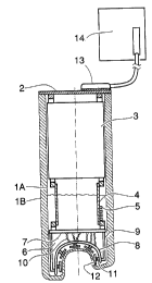
According to Fig. 1, the magnetometer proper is inside a dewar, consisting of
an inner vessel (lA) and an outer vessel (1B); the vacuum space between the
shells contains also radiation shields which are not shown in the figure. The
main parts of the magnetometer are: a top plate (2) made of multilayer
printed circuit board, functioning also as a motherboard, neck plug (3) made
of foam plastic, functioning also as a electrical connecting element (cable),
connecting elements (4) inside liquid helium, a cross-connection element (6)
and sensor elements (12).
The SQUIDs and flux transformers employed to measure the magnetic field
or its gradients are inside separate and independent components, sensor
elements (12) which are then connected to the magnetometer body with
connectors. Each sensor element (12) can also contain several SQUIDS with
their flux transformers. The lowest part of the magnetometer insert is a
support shell (8) following the shape of the dewar bottom; connectors (11) to
which the sensor elements (12) are attached reside on this shell. The dewar
bottom has been adapted to the shape of the head. The support shell (8) is at-
tached via one mechanical connecting element or via several mechanical
connecting elements (9) to a printed circuit board (motherboard) (7); the
connectors (11) are wired to this motherboard using, for example, twisted
pairs (10). A detailed construction and the means to attach them
is shown in Canadian Patent Application Serial No. 2,057,455 filed December
10,
1991 "Compact magnetometer probe and an array of them covering the whole
human skull for measurement of magnetic fields arising from the activity of
the
brain" by Ahonen, Knuutila, Simola, and Vilkman. The motherboard (7), con-
necting elements) (9), support shell (8), the connectors (lI) and the wiring
(10) form a unit (6) which can separately assembled and tested. The mother-
board (7) has also connectors to which the rectangular-shaped sup-
port/electrical connector parts (4) made of printed circuit board are
attached.
The electric components (5), necessary for connecting the SQUIDS to elec-
tronics at room temperature, reside also on the printed circuit boards (4) and
(7). The printed circuit boards are connected to the uppermost part of the in-
sert, a motherboard (2) functioning also as a top plate of the dewar, via a ra-
diation shield/cabling unit (neck plug) contalnlng at both ends electrical
connectors fitting to the connectors on the top plate (2) and the connector
9
parts (4). If necessary, the mechanical support by the connectors between the
various units (2, 3, 4, 6) can be secured by using, for example screws. On top
of the motherboard (2) there are connectors onto which the cables leading to
the electronics unit (14) are attached. Because of the special read-out tech-
nique, it is not necessary to place the electronics unit close to the SQUIDs
as
possible, i.e. on top the dewar.
A preferred embodiment for the connecting element (9) has been shown in
Figure 2. The element (9) consists of a Thin cylindrical fiber glass tube
whose
lower end has been cut to fit the support structure (8) following the shape of
20 the head. The tube (9) has several transverse cuts (25); because of these,
the
connection of the support shell (8) is flexible, compensating possible
stresses
caused by different thermal contractions of the materials. The spring action
created by the cuts (15) in the axial direction also presses the support shell
(8)
against the dewar bottom. To center the magnetometer insert with respect to
the dewar and to support the insert in lateral direction against the dewar
walls the tube (9) can also contain tongue-shaped springs cut in the tube
(16),
having small elevations fI~) made of a easily gliding material, for example
lVylonTM of TeflonTM. The spring presses, in the radial direction, the eleva-
tions (27) against the dewar wall.
The neck plug (3) is shown in Fig. 3. This part acts as a radiation shield
plug
and a cable between the room temperature electronics and the parts at liquid
helium; in addition, it guides the outflow of the helium gas. A cylindrical
plug is filled with foam plastic (20), for example polyurethane. The ends (18)
of this cylinder have been made of glass fiber plate, and they contain open-
ings for electrical connectors (22) and for a tube (25) necessary to transfer
he-
lium. The outer surface of the plug has been laminated with a thin fiber
glass layer (19) , firmly attached to the faam plastic. The flat ribbon cables
(23)
have been attached, for example, using small printed circuit boards (24) to
connectors (22) and laminated between the foam plastic (20) and the fiber
glass layer (19), Inside the foam plastic there are some metallic plates (2~)
parallel to hhe end plates. The plates (21) can be made, for example ouk of
copper mesh or printed circuit board, and they guarantee an even tempera-
ture distribtztian inside the foam plastic.
The structure of the flat ribbon cables (23) has been shown in liig. 4. A
rnetal
lized plastic film or paper (26) is placed on a drum, and prefabricated insu
lated twisted pair cable (28) is wound on the metallized surface. 'The coil is
~~':~'~~f~~~
impregnated with epoxy resin (27), and after polymerization of the epoxy the
cable is removed from the drum, connected to tile cormectors (22) in Fig. 3,
and the metallized film or paper (26) is grounded using the connector (22) in
order to shield against capacitively coupled disturbances.