Note: Descriptions are shown in the official language in which they were submitted.
205~50S
WAVELENGTE~ C:UN V$hl~h
BACKÇROIJND QF TT~F TNVENTIQN
Field of the Tnvention
The present invention relates to a wavelength
converter which generates from an ineident laser
light beam a second harmonie of the laser light beam, and
is easily positioned within a light souree deviee and/or
outputs the second harmonie laser light as parallel rays.
DescriPtion of the Related Art
Second harmonies of laser light occur in a medium
due to the nonlinear optical effect. This phr~"r--nr,n
causes the generation of seeond harmonies when the
polarization of laser light ineident on a medium is
proportional to the second and higher degrees of the
electrie field of the ineident laser light.
~aterials in which the nonlinear optical effect
occurs are called nonlinear optical materials. The
2 0 inorganic materials KH,PO, and 1iNbO, are currently used
~ 2~5~0~
nonlinear optical materials. Organic material 2-methyl-
4-nitrileanilin (~INA~ has attracted some attentiol~ as a
nonlinear optical material because it has a superb
nonl inear optical constant .
Typical wavelength converter confine the
fundamental component (i.e. incident laser light) using
high energy density nonlinear optical materials, wherein
the interaction of the harmonic components and the
fundamental components is elongated. For this reason,
an optical wave guide type of wavelength converter
is used. This type of wavelength converter has a
narrow wave guide, within which light propagates, formed
on a substrate; and the wave guide and substrate are
covered with an overlayer. In order to produce copious
amounts of second harmonic light, the optical wave guide
must accept a phase propagating velocity of the second
harmonic. In other words, the fundamental component must
phase match the second harmonic c~mr~n ~nt. The simplest
method known for obtaining this phase match is based on
Cerenkov radiation.
The Cerenkov method of phase matching follows.
Shown in FIGURE 1 (PRIOR ART), a second harmonic light is
generated from light propagating through an optical guide
portion 121 at point A. The second harmonic light
propagates at and angle ~, with respect to the optical
axis of the optical guide portion 121, towards a
substrate 122 and an overlayer 123. After a
predetermined time period, the second harmonic light is
2~57~0~
generated at point B as generated at point A. If the
equiphase plane of the second harmonic light generated at
point A is coincident with that of the second hA i c
light generated at point B, then the second h~ ic
5 light is emitted. The emission of the second harmonic
light is in the direction of angle ~. If the following
relation holds:
nS(2w) > nG(w) > nS(w), -- (1)
where, nS (w~ is the refractive index of the
substrate 122 for the fundamental component,
nG (w) is the refractive index of the wave
guide portion 121, and
nS(2w) is the refractive index of the
substrate 122 for the second harmonic c n~nt;
phase matching occurs.
In an optical wave guide type of wavelength
converter as described above, the flux of light
20 rays propagating through the wave guide is accurately
shaped in cross section; however, ~ n~-~ncation of the
emitted light rays is poor. In other words, the emitted
light rays cannot be condensed into a small spot.
Therefore, it is difficult to utilize the second
25 harmonic light for writing data into and reading data out
of an optical recording medium, such as an optical disk.
It has been demonstrated that an optical fiber
type of wavelength converter as shown in FIGURE 2
20~75Q~
can realize a high density recording in an optical disk.
Wavelength converter 130 of the optical fiber type
includes a core 131 and a clad 132 having refractive
indices satisfying equation (1~. The second harmonic
light 133 emitted from the end face expands in the forr~
of a rotational symmetric ring. Accordingly, this type
of wavelength converter has an excellent
condensing characteristic.
To condense the emitted light rays of a
wavelength converter of the optical fiber type, it
is necessary to collimate (make parallel~ the emitted
light rays. Japanese Patent Unexamined Publication Nos.
Hei. 1-287531, 1-293325, 2-35423, 2-153328, and 2-186327
disclose techniques to collimate emitted light ray~.
In Japanese Patent UnP~mi nPd Publication No. Hei
1-287531, there is disclosed a light source device in
which a circular cone prism, used as a collimating lens,
collimates second harmonic light emitted from a
wavelength converter of the optical fiber type.
Shown in FIGURE 3, is the technique disclosed in
Japanese Patent UnP~minPd Publication No. Hei. 2-153328
for collimating emitted light rays using a Fresnel lens
151. The Fresnel lens 151 incorporates a concentric
circular diffraction grating directed towards the light
emitting end face 150a of wavelength converter
150. Once the emitted light rays have been collimated
the light rays can be easily condensed.
20~7505
In both devices described above, it is difficult
to position the wavelength converter within a
light source device due to the small size (1 to 2 um) of
the wavelength converter. The devices also have
5 the disadvantage that it is difficult to properly align
the optical axis of the wavelength converter with
the axis of rotational symmetry of the collimating lens.
Furthermore, difficulty arises in the correct adjustment
of the distance between the light emitting end face of
10 the wavelength converter and the collimating lens;
exact positioning is quite complicated.
The device disclosed in Japanese Patent
TJ n~ pllhl ir`At;ttr` No. Hei . 1-293325 is shown in FIGURE
4. As shown, the light emitting end face of the optical
fiber 141 is --rh;n~ l to a circular slanting surface 141a
for collimating emitted second harmonic light.
This device has the drawback that the light
emitting end face must be accurately machined. Often in
~ hin;n~ the light emitting end face is broken or
2 O scarred; thus reducing the amount of second harmonic
1 ight emitted .
SUr~ARY OF T~TF INV~NTION
The obj ect of the present invention is to
25 simplify the positioning, alignment and construction
problems of conventional wavelength converter of
the optical f iber type .
~ 2~575a~
~ he objectives of the present invention are
achieved by providing a wavelength converter of
the optical f iber type and a method for its production.
The optical f iber core and/or cladding is made of
5 nonlinear optical material such that copious amounts of
second harmonic light are emitted.
In a first and second embodiment, a groove or
flange is formed circumferentially in or on the clad.
In a third and fourth embodiment a transparent layer is
10 formed on at least the outer surface of the clad and a
groove or flange is formed circumferentially thereon.
The groove and flange allow easy and quick positioning of
the wavelength converter within a light source
device .
In a fifth and sixth embodiments, at least the
end face emitting the second harmonic light i5 covered
with a transparent layer, and formed on the light
emitting end face of the transparent layer is a
collimating means for collimating the second harmonic
20 light.
In operation, fundamental light propagates
through the nonlinear fiber optic which produces second
harmonic light. The emitted second harmonic light passes
through the transparent layer and is collimated by the
25 collimating means formed on the light emitting end face
of the transparent layer. The collimating means
eliminates the need for a separate collimating lens and
2~S7505
eliminates any positioning and/or ~l iqnin~ pro}~lems
involved when using a separate collimating lens.
In another aspect, the present invention pro~ides
a wavelength changing element of an optical fiber type
5 comprising: a core; a clad covering said core, at least one
of said core and clad being made of a n~nl in~ ~r optical
material; a transparent layer covering said clad, said
transparent layer having a groove formed circumferentially
therein; and wherein said transparent layer covers a light
10 emitting end face of said optical fiber; and said
transparent layer has a collimating means formed at said
light emitting end face for collimating rays of light
propagating in said optical f iber.
Other objects, features, and characteristics of
15 the present invention; methods, operation, and functions of
the related elements of the structure; combinatioll of
parts; and economies of manufacture will become app~rent
from the following detailed description of the preferred
embodiments and ~ -nying drawings, all of which form a
20 part of this specification, wherein like reference numerals
designate corr~cpon~ i n~ parts in the various f igures .
BRIEF DESCRIPTION OF THE DRAWINGS
FIGURE 1 is a diagram for explaining the prior
25 art phase matching method based on Cerenkov radiation.
FIGURE 2 is a diagram showing the shape of light
rays emitted from a prior art wavelength converter of the
optical f iber type .
,; ~ -
2~7~
FIGURE 3 is a sectional view of a prior art
device for collimating light rays emitted from a wavelength
converter of the optical f iber type shown in FIGURE 2 .
FIG~RE 4 is a sectional view of a prior art
5 device of a wavelength converter of the optical f iber type
which emits collimated light rays .
FIGURE 5 is a sectional view of a wavelength
converter according to a first ~ t of the present
invention .
7a
:
~ 2~57~
FIGURE 6 is a schematic diagram showing a light
source device using the wavelength converter of
the f irst embodiment of the present invention .
FIGURE 7 is a perspective view showing the
5 construction of a holder for holding the wavelength
converter of the first e-ho~l;m~t.
FIGURE 8 is a schematic diagram showing another
light source device in which an additional structure is
used for positioning the wavelength converter.
FIGURES 9 and 10 are sectional views showing a
wavelength converter according to a second
embodiment of the present invention.
FIGURES 11 (a) and 11 (b) are a perspective and
sectional view of a wavelength converter according
15 to a third embodiment of the present invention.
FIGURE 12 is a sectional view of a wavelength
converter according to a fourth emoodiment of the
present invention.
FIGURE 13 is a variation of the wavelength
20 converter shown in FIGURES 11 and 12.
FIGURE 14 is a sectional view of a wavelength
converter = according to a fifth embodiment of the
present invention.
FIGURE 15 is a sectional view of a wavelength
25 converter according to a variation of the fifth
f~mho~l; r nt .
~ ~ 2~750~
FIGURE 16 is a sectional view of a wavelength
converter according to a sixth Pmho~r l of the
present invention.
FIGURE 17 is a sectional view of a wavelength
5 converter according to variation of the sixth
embodiment .
FIGURES 18 (a) - 18 (d) are sectional views of
variations of the wavelength converter according
to the fifth and sixth embodiments of the present
10 invention.
FIGURE 19 (a) - 19 (d) are sectional vie~is of
further variations of the wavelength converter
according to the fifth and sixth Prhorlir-ntS o~ the
present invention.
FIGURES 20 (a) and 20 (b) are sectional views of a
wavelength converter according to a further
embodiment of the present invention.
FIGURES 21-23 are longitudinal sectional views
for explaining a method of manufacturing a wavelength
20 converter according to an embodiment of the
present invention.
FIGURES 24-26 are longitudinal sectional views
for explaining the method of manufacturing a wavelength
converter of FIGURES 21-23 according to another
25 embodiment of the present invention.
2~57~5
DESCRIPTION OF THE PREFERRED EMBODIMENTS
FIGURE 6 is a schematic diagram showing a light
source device using a wavelength converter
according to an embodiment of the present invelltion.
Laser light rays emitted from a laser light source 1,
5 such as a semiconductor laser, are collimated by a
spherical lens 2. The collimated laser light rays are
condensed by a spherical condenser lens 3, and incident
on a wavelength converter 4. The laser light
source 1, spherical lens 2, spherical lens 3, and the
10 wavelength converter 4 are positioned at and fixed
to holders 51, 52, 53, and 54 integral with a base 50 by
means of an adhesive. Wavelength converter 4
being positioned orthogonal to its optical axis 10 as
shown .
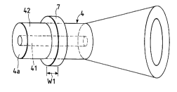
Shown in FIGURE 5 wavelength converter 4
is of the optical fiber type. The wavelength
oonverter includes a core 41, a clad 42, and a flange 7
around the circumferential outer surface of clad 42. The
core 41 and/or clad 42 are made of nr nl i nf~r optical
material, such as MNA (2-methyl-4-nitrileanilin). The
flange 7 is made of high polymer, transparent material,
such as diglycoldiallyylcarbonate, polymethylmetacrylate
(PMMA), polystyrene, polycarbonate, and polymicrohexyl
methacrylate .
2 5 FIGURE 7 is a perspective view showing the
construction of the ~older 54 to which wavelength
converter 4 is fixed. The upper surface 55 of the
holder 54 is V shaped, simplifying the positioning of
~ ~ 20~5~.~
wavelength converter 4 orthogonal to its optical
axis 10. A groove 56 formed in the upper surface has
width W2 slightly wider than width Wl of flange 7 for
receiving flange 7. Thus wavelength converter 4
5 mounts on holder 54 with flange 7 received in groove 56.
The holder 54 is located such that when
wavelength converter 4 is attached, the incident
end face 4a is at or near the focal point of the laser
10 beams emitted from the spherical lens 3. Therefore,
wavelength converter 4 can be roughly positioned
by merely fitting the flange 7 of the wavelength
converter 4 into the groove 56. Thereafter, the wavelength
converter 4 is finely positioned by being
15 displaced along the optical axis 10, within the range of
clearance between the flange 7 and the groove 56. The
accuracy of the positioning being in the order of a
submicron. After the positioning operation, the
wavelength converter 4 is f ixed to the holder 54
by adhesive.
Accordingly, the positioning work of the
wavelength converter 4 is remarkably improved, and
can be completed in a short time.
Fine positioning work of the wavelength converter
25 4 may also be made using a holder 57, which is
separated from the base 50, as shown in FIGURE 8. In
this case, the wavelength converter 4 is bonded to
the holder 57 as described above. A concavity 59 formed
11
-
~ ~ 205750~
in the bottom surface of the holder 57 is applied to a
positioning protrusion 58 of the base 50. The holder 57
is properly displaced along the optical axis 10 of the
wavelength converter 4 within the range of a
clearance between the protrusion 58 and the concavity 59.
At the completion of the fine positioning work, the
holder 57 is bonded to the base 50.
FIGURE 9 is a perspective view showing a second
embodiment of the present invention. In this embodiment,
a ring-shaped groove 61, for positioning purposes, is
formed on the circumferential surface of the clad 42 by
a suitable grinding means, such as a diamond grindstone.
A protrusion fitting into the groove 61 is formed on a
holder of the wavelength converter (not shown).
The groove 61 like flange 7 allows the wavelength
converter to be positioned quickly and easily.
Paired grooves 62, formed by cutting out the
wavelength converter 4 as shown in FIGURE 10, may
be used in place of the ring-shaped groove 61.
FIGURE 11 (a) is a perspective view showing the
construction of a third ~mh~ ;r-nt of the present
invention. FIGURE 11 (b) is a longitudinal sectional view
of the structure of FIGURE ll(a). In this embodiment,
the wavelength converter 4 is enclosed by a
tubular, transparent layer 5 made of high polymer
material, such as diglycoldiallyylcarbonate,
polymethylmetacrylate (P~IMA), polystyrene, polycarbonate,
and polymicrohexyl methacrylate.. A flange 66 as a
12
~ ~ 2~57~
positioning protrusion is formed around the
circumferential surface of the transparent layer 5.
Flange 66 permits positioning similar to that
described with respect to flange 7 above. FurfhP e,
the increased diameter of the structure provides easy
handling of the wavelength converter 4, and since
the wavelength converter 4 is protected by the
high polymer transparent layer 5 scraping is prevented.
If distance D, the amount of transparent layer between
the laser beam incident end face 5a of the transparent
layer 5 and the incident end face 4a of the wavelength
converter 4, is sufficiently long; a satisfactory
amount of laser light can be gathered into the core 41
through the incident end face 4a irrespective of minor
scrapes on the incident end face 5a.
A positioning groove 67, shaped like a ring as
shown in FIGURE 12, may be used in place of the flange
66. Alternatively, as shown in FIGURE 13, a positioning
groove 69 and a flange 70 may be formed on and in the
transparent layer 5. In FIGURE 13, the incident end face
4a of the wavelength converter 4 is clearly
distinct from the light emitting end face 4b. An
operator will not confuse the incident side Wit~l the
emitting side of wavelength converter 4.
The positioning flange and/or groove is not
limited to a ring shape, but may take any other suitable
shape. Furthermore, one or more flanges and/or grooves
13
20~75~
may be circumferentially arranged on the outer surface of
the transparent layer 5.
A fifth e ` ~';r-nt of a wavelength converter
4 of the optical fiber type according to the
5 present invention is shown in FIGURE 14.
On the 6econd harmonic light emitting end face 5b
of transparent layer 5 is formed a collimating means in
the form of a concentric circular diffraction grating
means. The concentric circular diffraction grating means
10 is centered at the optical axis 10 of the wavelength
converter - 4, and consists of rectangular sha]?ed in
cross section gratings linearly arrayed at equal pitches
A: which function like a Fresnel lens. A laser light ray
emanating from the spherical lens 3 propagates through
15 the transparent layer 5, and enters the core 41 of the
wavelength converter 4 through the incident end
face 4a. Within the wavelength converter 4,
Cerenkov radiation of the incident laser light occurs,
and the second harmonic light generated propagates within
20 the clad 42 in the direction de~ined by angle eO with
respect to the optical axis 10. The second harmonic
light is subjected to diffraction at the light emitting
end face 4b due to the difference between the refractive
indices of t~e clad 42 and transparent layer 5. The
25 diffracted second harmonic light propagates through the
transparent layer 5 in the direction defined by angle ~,
with respect to the optical axis 10. The rays of the
second harmonic light are then collimated by the
14
20575~5
concentric circular diffraction grating at the light
emitting end face 5b.
In order to achieve proper collimation of the
second harmonic light rays, the pitch A of the gratings
5 is set according to the following equation:
A= m~/sin e, ... (2)
(where ~ is the wavelength of the second l~ nic light,
and Iq = 1, 2, 3, .. ).
The angles eO and e, satisfy the fol] owing
equation:
nO sin~0 = n, sine, . . . (
(where nO is the refractive index of the clad 42 and n, is
the refractive index of the transparent layer 5 for the
second harmonic light), and the angle ~0 is expressed as:
2 0 coseO = N/nO ( 4 )
(where N is the effective refractive index of the
propagating mode of the incident laser light).
Since, collimated rays of second harmonic light
25 are emitted from light emitting end face 5b, there is no
need for complicated positioning of the wavelength
converter 4 or a Fresnel lens. Furthermore, when
the collimated light rays are ~condensed by a known
~ 205750~
condensing means, a light spot substantially coincident
with the diffraction limit is formed.
The shape of the diffraction gratings formed on
the light emitting end face 5b of the transparent layer
5 5 are not limited to being rectangular shaped in cross
section as shown in FIGURE 14. A concentric circular
diffraction granting means having gratings sawtooth
shaped in cross section, as shown in FIGURE 15, provides
an increased diffracting efficiency. In this case, it is
10 preferable that angle e of the slanting surface 8 of the
concentric circular diffraction grating with respect to
the optical axis 10 satisfies the following equation:
tan e = (n, cose, - 1) / sine, . . . (5)
I'he collimating means is not limited to a
concentric circular diffraction gratings. A sixth
emoodiment, shown in FIGURE 16, shows a cross section of
wavelength converter 4 in which the transparent
20 layer 5 has a circular cone surface 90 at the light
emitting end face 4b. The circular cone surface has a
vertex angle of 2~ and collimates the second harmonic
light emitted at light emitting end face 4b. The axis of
rotational symmetry of the circular cone surface 9o is
25 coincident with optical axis 10 of the wavelength
converter .
In order to collimate the second harmonic light
emitted from the light emitting end face ~b, the vertex
16
~ 2~5~
angle ~ of the circular cone surface 90 is selected to
satisfy the following relation based on the Snell laws
of refraction:
[ (n,' - nO'sin2eO) '" - 1]/nOsine~ = tan ~ . . . (6)
Since, collimated rays of second harmonic light
are emitted from light emitting end face 5b, there is no
need for complicated positioning of the wavelength
10 converter or a Fresnel lens. Furthermore, when
the collimated light rays are condensed by a known
condensing means, a light spot substantially coincident
with the diffraction limit is formed.
The shape of the circular cone surface 90 is not
15 limited to that shown in FIGURE 16. As shown in FIGURE
17, a tip of the circular cone surface 90 where no second
harmonic light passes may be cut off forming planar end
face 91 (i.e. a conical frustrum).
Furthermore, high polymer transparent layer 5 may
20 have various shapes such as shown in FIGURES 18 and 19.
A ring-like groove 67 may be formed on the
circumferential outer surface of the transparent layer,
as shown in FIGURES 18 (a) and 18 (b), or a flange 66 may
be formed around the circumferential outer surface as
25 shown in FIGURES 18 (c) and 18 (d) . Provision of the
groove 67 or the flange 66 make it easy to position the
wavelength converter 4 when assembling the
wavelength converter 4 into a light source device.
~ 2~7505
In FIGURES l9 (a) and 19 (b), the incident end face 5b is
shaped like a spherical (or aspherical) condenser lens.
In FIGURES 19 (c) and 19 (d), a diffraction grating means
formed on the incident end face 5b acts like a Fresnel
5 lens. The variations illustrated in FIGURE 19 eliminate
the use of a spherical condensing lens (such as the
spherical condenser lens 3 for condensing the laser light
rays of the laser light source 1 shown in FIGURE 6) thus
simplifying a light source device.
In a further embodiment of the present invention,
the incident end face 4a of the wavelength con~erter
4 is protruded from the transparent layer 5 as
shown in FIGURES 20(a) and 20(b). The protruded incident
end face 4a allows clear perception by an operator of the
wavelength converter 4, making positioning of the
wavelength converter 4 within a light source
device easier.
Additionally, only the light emitting end face 4b
of the wavelength converter 4 may be covered with
the transparent layer 5; the circumferential outer
surface of the clad 42 not being covered with the
transparent layer (not shown). A collimating means is
formed solely on the light emitting end face 5b of the
transparent layer.
The following is a description of a method of
constructing a wavelength converter according to
the present invention. In the description to follow, the
manufactured wavelength converter is the
18
. ~ 2~575~
embodiment shown in FIGU~ 15, in which the light
emitting end face 5b of the transparent layer 5 is Lormed
with a concentric circular diffraction grating means
consisting of gratings sawtooth shaped in cross section.
It is to be understood that by varying the mold any of
the above embodiments may be produced from this method.
The melt of 3, 5-dimethyl-1-(4-nitrophenyl)
pyrazole was sucked, by capillary action, into a
capillary tube of SF 15 glass having an inner diameter of
0 . 8 ~m and an outer diameter of l. O mm. Monocrystalline
was grown from an end of the capillary tube by the
Bridgman method, thereby forming a wavclength converter
4 of the optical fiber type. The wavelength
converter 4 formed was cut to obtain a wavelength
converter of 5. 0 mm long. One end of the
wavelength converter 4 was abraded to form a light
emitting end face 4b. A semiconductor laser beam of
0.884 /~m in wave length was input to a core o~ the
wavelength converter 4- A laser light of
wavelength 0.442 ~m was emitted at a radiation angle, the
angle of the light emitted with respect to the optical
axis of the wavelength converter of 12- from the
light emitting end face 4b.
The refractive index of the SF 15 glass (clad)
was l . 727 for light with a wavelength of O . 442 ~m, and
the radiation angle ~within the clad was 6 . 9 ' . Then,
shown in FIGURE 21, the wavelength converter 4 was
put into and held in a tubular mold 11 (of which the
19
~ 2~
inner diameter is 2 mm). The ~ottom of the tubular mold
11 has an impression of a concentric circular diffraction
grating means for molding a transparent layer material
into a concentric circular diffraction grating with
gratings arrayed at a predetPrminpd pitch (i.e. A = 3.3
/~m), and each grating having a slanting surface at a
predetermined angle e (i.e. e - 76.0 ). Nextr the
optical axis of the wavelength converter 4 was
aligned with the axial line of the tubular mold 11, and
the abraded light emitting end face 4b was directed
toward the ~ottom of the tubular mold 11. The tubular
mold 11 has a cover lla with a hole 12 at the central
part. By merely in~erting the wavelength
converter 4 into the hole 12, the optical axis of the
wavelength converter 4 is automatically aligned
with that of the tubular mold 11.
A solution containing l'~A (methyl methacrylate)
and l-hydroxycycloheXly phenyl ketone, as optical
polymerizaton initiator at the weight ratio of 99 . 9
0.1, was put into the tubular mold 11 with the wavelength
converter 4 fixed thereto. Subsequently, the
solution was irradiated with ultraviolet rays to
polymerize the M~A, thereby forming P~A (polymethyl
methacrylate) 13. The refractive index of the PMMA was
1. 55 for light of wavelength 0 . 442 I-m.
To increase the adhesiveness of the P~A to the
clad glass at the time of polymerization, it is advisable
~, 205750~
Tat approximately 1% by weight of diethoxydivinylsilane
be added to the above solution.
Thereafter, the non-light emitting end of the
wavelength converter 4 was cut of f, resulting in
5 a wavelength converter of length 1 mm, as shown in
FIGURE 22. ~MA was added again and polymerized to form
P~MA 14, which together with the PMMA 13 comprises the
high polymer, transparent layer 5, as shown in FIGURE 23.
Then, the structure thus formed was pulled out of the
10 tubular mold 11, and the P~MA surface to serve as the
incident laser light end of wavelength converter
was abraded.
A semiconductor laser beam of wavelength 0.884 ~m
was input to the core of the wavelength converter
15 4 thus manufactured. The collimated light emitted from
light emitting end face 5b had wavelength 0 . 442 ~m.
In the above, the concentric circular diffraction
gratings are formed on the light emitting end face 5b of
the transparent layer 5 by using the tubular mold 11
20 having a bottom surface with the shape of the concentric
circular diffraction grating. Alternatively, the
concentric circular diffraction grating may be formed on
a flat light emitting end face by spin coating the light
emitting end face with resist, and forming the
25 diffraction gratings by a photolithography or electron
beam lithography process.
FIGURES 24, 25 and 26 illustrate the molding
process described above using a mold for forming the
21
. ~ ~ 2D57~0~
wavelength converter having a circular cone
surrace 90 with a vertex angle 2~ (2~p 5 133 . 7) formed on
the transparent layer 5 at the light emitting end face 4b
and flange 66 formed circumferentially around transparent
5 layer 5.
While the invention has been described in
connection with what is presently considered the most
practical and preferred ~ a;r-nts, it is to be
understood that the invention is not limited to the
10 disclosea embodiments, but on the contrary, is intended
to cover various modirications and equivalent
arrangements included within the spirit and scope Or the
appended claims.