Note: Descriptions are shown in the official language in which they were submitted.
~, Z057605
INTRODUCTORY DESCRIPTION OF THE INVENTION AND PRIOR ART
It is unfortunately common in urban environments
for large sections of the streets to be dug up
periodically to replace aged and leaking underground
piping, or to install new piping. The cost is great
even figured solely on manpower and equipment; much
greater when snarled traffic (and public aggravation)
is included. Trenchless pipeline installation avoids
many of the problems listed, but to date the standard
widely-used plastic components for water and sewer
mains, having bell and spigot joints, have not been
appropriate for trenchless use. They become damaged at
the joints if attempted to be pipe-jacked ~pushed or
pulled into the hole). The present invention
ingeniously allows these common components to be
installed without damage.
This allows for a great cost saving since before
the present invention more expensive pipes joined by more
expensive techniques were necessary in trenchless
applications. Thus with the present invention the
public is likely to get home from work more quickly and
find a smaller tax bill in the mail box.
In brief, the invention is as follows: instead
of the bell and spigot joint which is now widely used in
standard PVC (polyvinyl chloride) watermain and sewer
- 2 -
~, Z()5~605
pipe, the inventor has specified the same pipe but with
bells on both ends. This calls for no ~actory
retooling, merely a labour motion of turning the pipe
during manufacture. During pipe-jacking according to
the invention, two pipes are placed end-to-end, the
bells line up exactly, and the bells transfer the
longitudinal load smoothly. A separate piece of
straight (bell-less) pipe, or nipple, has at this point
been installed inside the pipes at the joint, and makes
liquid-sealing contact against gaskets inside the bells.
These gaskets are already part of the bell-formation
process since they are an integral part of the original
bell and spigot connection. Now however, two gaskets
are flush against the nipple instead of one against a
spigot.
The invention resides in the fact that the force
of pipe-jacking is not transmitted through the nipple,
which is completely isolated from this force. In common
PVC bell and spigot configurations, pipe-jacking above a
certain short distance causes the spigot and/or its
matching bell, to be damanged eventually causing a
rupture. A square-shouldered bell might accommodate
this, but would be more difficult to make and requires
modification of existing manufacturing equipment
disproportionate to the size of the market for
trenchless installation.
~_, Z057605
In minor variations, the inventor has also
devised a bearing ring which can be placed around the
nipple between the bells, to ensure no abrasion of the
bell surfaces during installation; a bearing and anchor-
ring that will also prevent lateral movement of the
nipple ~wherein a groove is scored in the nipple to hold
the ring); and a custom-molded nipple that contains its
own bearing ring and is hence anchored. In all cases
the essential bell-to-bell load-bearing of the invention
prevails.
A search of the relevant prior art has revealed
only pipe-coupling inventions that have a superficial
visual resemblance to the present invention, but were
not intended for trenchless applications. On
examination they can easily be shown to suffer from the
same serious flaw as the common bell and spigot PVC:
a rupture would be caused with the heavy end-loading
required for trenchless installation. For example,
Canadian Patent No. 877,834 (Ellay Enfield) is
superficially similar but designed for a different
purpose: for the provision of end restraint on pipes installed
by conventional means. Any applied end-load would be borne on
curved surfaces, and would crack in exactly the same manner as
common bell and spigot PVC. As well, the components are not
standard, requiring extensive retooling; and the clip
_ .~
20S~605
system would dislodge during installation. Finally the
size of the pipeline would be determined by the
size ~nominal inside diameter) of the nipples, rather
than the size of the pipe itself.
Similarly, with the other prior art:
Canadian Patent No. 1,029,416 (Dupont) is intended for
repair; Canadian No. 869,429 IA.M.F.) is designed for
welding of steel pipe; Canadian No. 635,412 is for
threaded metal couplings. In all the foregoing the
essential features of this invention are not addressed:
1) they do not isolate the spigot component of the
coupling from the pushing force necessary for pipe-
jacking or other trenchless pipeline replacement
installations; 2) They do not employ existing standard
production coupling components. Finally, in ~.S. No.
3,360,283 ~Guthrie), the diameter of the line would be
governed by the diameter of the nipple rather than the
pipeline itself, and the components are all non-standard
relative to existing sewer and water line
specifications, necessitating extensive retooling. The
stated use of the Guthrie patent is "circuits requiring
frequent assembly and disassembly, such as agricultural
circuits," and also where "limited space is normally
available for installation such as in heating and air
conditioning ducts", the question of trenchless end-
~ 205760S
loaded installation is not contemplated or addressed.
One object of the present invention is
to provide a method and apparatus for pushing jointed
plpe comprislng:
(a) a plurality of substantially identical
lengths of pipe with integral extruded annular flanges,
called bells, on both ends, such that the maximum inside
diameter of the bell is greater than the outside diameter
of the body of the pipe;
(b) a similar plurality of substantially
identical nipples, being shorter lengths of straight
pipe, positioned such that there is one nipple inserted
between two opposing bells when the longer pipe lengths
are coupled end to end; said nipples being bevelled on
both ends, and said nipples being shorter in length than
the shortest distance between the two inside sloping
surfaces of said opposing bells when the ends of the
opposing bells are annularly touching; said sloping
surfaces being the connecting surface between the
maximum inside diameter of bell and minimum inside
diameter of the body of the pipe;
(c) a means of forming an annular seal between
the outer surface of the nipple and the inner surface of
the bell; said seal being appropriate to contain inside
. .
~ 20S~605
the pipe whatever is being transported in the pipe;
~ d) a means for longitudinally pushing the end
of the coupled line of pipes, or pipeline; said means
having sufficient force to move the entire pipeline
longitudinally; and
(e) means for positioning subsequent nipples
and pipes onto the penultimate pipe.
Another object of the invention is to provide a
method and apparatus for pushing jointed pipe such as
just described in (a) through (e), except that an
annular ring, called a bearing ring, is placed between
the outer surfaces of the two opposing bells in the
coupling, for the purposes of preventing abrasion
between said surfaces during installation; said bearing
ring being designed so as to effectively transmit the
longitudinal pushing force from bell surface.
Another object of the invention is to provide a
similar method and apparatus for pushing jointed pipe as
that just described in (a) through (e), except that
instead of the annular ring just described, an annular
groove is machined in the outer surface of the nipple,
and an annular ring, called a retainer ring, fashioned
to fit securely in the groove; said secure fit in the
groove being sufficient to prevent lateral movement of
the nipple during installation.
"
~_, Z057605
Another object of the invention is to provide a
similar method and apparatus for pushing jointed pipe as
that just described in ~a) through (e), except that
instead of the separate retainer ring just described,
the nipples are fashioned as a single piece with an
annular ring extending outwards from their lengthwise
midpoint.
A further object of the invention is to provide
a means of coupling PVC, that is polyvinyl chloride,
gasket-jointed AWWA, that is American Water Works
Association, Standard C-900 and CSA B137.3M86 watermain
pipe in trenchless installation, comprising:
(a) obtaining said watermain pipe appropriate
in diameter and length for the installation being
performed, except manufactured with standard bells with
standard annular gaskets on both ends instead of on
one end only;
(b) obtaining for each length of said watermain
pipe one nipple, being a bell-less shorter length of
AWWA Standard C-900 watermain pipe; said nipples being
bevelled on both ends; said nipples being shorter in
length than the shortest distance between the two inside
sloping surfaces of opposing bells when the ends of
bells of two lengths of longer pipe are annularly
touching; outside unbevelled surface of said nipples
~,, 20S760S
being longer in length than the shortest distance
between one side sloping surface of one bell and the
gasket in the opposing bell; said sloping surfaces being
the connecting surface between the maximum inside
diameter of bell and the minimum inside diameter of the
body of the pipe;
(c~ installing the first length of said double-
belled standard C-900 watermain pipe into the intended
watermain tunnel using known techniques, such that one
bell end is still outside the tunnel;
~d) inserting a nipple into said bell end, such
that its outside unbevelled surface extends farther than
the gasket in said bell end but not so far as to contact
the inside sloping surface of said bell end;
~e) placing another length of double-bell-ended
pipe over the extending nipple using known techniques,
and maneuvering it, using known techniques, towards the
penultimate pipe so that ultimately the bell-end faces
of the two pipes touch;
(f) applying tape, including but not limited to
common duct tape, annularly around the joint of the two
opposing bell-faces to prevent dirt entry into the
joint.
~g) pushing against the open end of the last
pipe, using known techniques, such that the two pipes
move longitudinally into the tunnel;
~ _ .
2(~S7605
~h) repeating steps ~d) through ~g) of the
description until the end pipe has been inserted into
the tunnel to complete the length of pipeline desired.
These examples are by way of illustration only,
and the process is intended to work equally well with
any type of end-loaded installation of jointed tubes.
To the inventor's knowledge, there is no prior
art that solves the problem of common component end-
loaded installation in a similar manner; therefore, the
invention may have applications outside the existing
specific use to be described. For this reason, the
reader is advised that the contexts discussed in this
introduction and the more detailed description to follow
are by example only and in no way are intended to limit
the scope of the appended claims.
In the following description, reference will be
made to the accompanying drawings in which:
Figure 1, a typical bell and spigot
gasket-seal joint according to prior art, unassembled;
Figure 2, a typical bell and spigot gasket-
sealed joint according to the present invention;
assembled;
Figure 3, a bell, bell, nipple gasket-sealed
joint according to the present invention; unassembled;
Figure 4, a bell, bell and nipple gasket-sealed
-- 10 --
_. . "
~ Z~57605
joint according to the present invention; assembled;
Figure 5, a cross-section of bell, bell and
nipple gasket-sealed joint according to the present
invention, additionally showing bearing ring and dirt
shield tape;
Figure 6, a cross-section of bell, bell and
nipple gasket-sealed joint according to the present
invention, additionally showing grooved anchored nipple;
Figure 7, additional cross-section of nipple
10according to the present invention shown in Figure 6,
clearly exhibiting radial and insert dimension;
Figure 8, a cross-section of bell, bell and
nipple gasket-sealed joint according to the present
invention, additionally showing nipple over-inserted
15into bell during installation;
Figure 9, simple push trenchless installation
method for pipes joined according to the present
invention;
Figure 10, simple push trenchless installation
20method for pipes joined according to the present
invention;
Figure 11, pulling or indirect pushing
installation method for pipes joined according to the
present invention;
25Figure 12, pulling or indirect pushing
~ ..~....
- ZOS7605
installation method for pipes according to the present
invention, showing components exploded;
Figure 13, pulling or indirect pushing
installation method for pipes jointed according to the
present invention, showing full length of operation;
Figure 14, cross-section of molded nipple with
integral bearing and anchor ring, according to the
present invention, with detail;
Figure 15, cross-section of a bell, bell and
nipple gasket-sealed joint according to the present
invention, showing molded nipple with integral bearing
and anchor ring; and Figure 16 is a detail, in enlarged
scale of a bearing ring butted against a bell surface.
Detailed reference will now be made to the
drawings in which like reference numerals will identify
like parts.
In a first version of the invention, trenchless
installation of PVC watermain pipe made to the American
Water Works Association (AWWA) Standard C-900 (also
CSA B137.3M86~ will be described. This is the
predominant type of pipe currently used in municipal
watermain installations throughout Canada and the U.S.A.
It should be understood that the invention is also
applicable to trenchless installations of any suitable
pipe with bell and spigot joints with annular gasket
.. - 12 -
~" 2~5~605
seals, for example, standard PVC sewer pipe (ASTMD3034,
F697; CSA B183.1, B182, known as "PSM" type).
Referring to Figure 3, an adequate number of
AWWA Standard C-900 watermain pipes 10 are ordered
manufactured with bells 12 on both ends. Inside each
bell is annular gasket 14. Enough pipe is obtained for
the complete length of the job being considered. For
each pipe is also obtained a short length of pipe 16,
also called nipple, with spigot on both ends.
As seen in Figure 5, the inside diameter 17 of
nipple 16 is equal to the inside diameter 19 of the AWWA
Standard C-900 watermain barrel 18.
The outer diameter 15 of the nipple 16 is less
than the inside diameter 13 of bell 12, so that the
nipple 16 will fit inside the mouth of bell 12, and snug
up against gasket 14 for a fluid-proof seal.
An assembled coupling is illustrated in Figure
4, and in Figure 5. Standard commercially available
straight pipe is commonly sold, and has the diameter sizes
required in nipples 16. Nipples 16 are also provided
with a bevel on both ends 21 ~ see Figure 5) and the
provision of such bevels is also readily available
commercially. The suggested bevel is about 15 over one
inch.
Referring to Figure 8, the maximum length of the
- 13 -
,_~
~_, 2Q57605
nipple 16 is calculated such that it is less than the
distance between the sloping shoulders 20 of the two
opposing bells 12, so that, as indicated in Figure 8, if
the nipple is over-inserted into the one bell during
installation such that a bevelled end 21 thereof
contacts the inside surface of sloping shoulder 20, the
other end of the nipple will not contact the opposing
shoulder. Thus, the longitudinal load will still be
borne between bell-mouth faces 23, and nipple 16 will not
be broken or deformed. Further, the nipple is provided
with a minimum length, also illustrated in Figure 8, so
that if the nipple is over-inserted to the left, as
illustrated in Figure 8, the nipple must be long enough
so that its unbevelled outer surface extends beyond
gasket 14 in opposing bell 20. This ensures a fluid-
tight seal even though the nipple 16 has been over-
inserted.
The inventor has devised three further versions
of the invention involving the contact of the opposing
bell-faces 23; these will be applicable in
different situations. Since trenchless installation
of the pipeline is identical for all variants, they
will be described now and the common installation
procedure afterwards.
- 14 -
i
Z~57605
It will be understood that relative movement
between bell-faces 23 during push or pull installation
may result in abrasion. Though likely insufficient to
cause damage because bell faces of standard
commercially-produced pipe bells are commonly flat, the
presence of high spots causing point-loads cannot be
discounted. Therefore, in a second version of the
invention, referring to Figure 5, an annular bearing-
ring 26 is provided between the bell-mouth faces 23,
positioned over the nipple 16. Bearing-ring 26 can be
fashioned by cutting rings 1/2" and 3/4" wide from
suitably sized pipe of polyethylene, PVC, or other
suitable material. Rings with inside diameter
dimensions to fit closely over C-900 and D3034 PVC
nipples 16 and with outside diameter 15dimensions
sufficient to form an ample bearing surface between
bell-faces may be cut from standard ASTM F714
polyethylene pipe. Finally, a layer of adhesive tape
26, standard duct tape, is to be applied around the
outside of the joint, to prevent dirt from entering the
coupling while the pipe is being pushed into place.
In the third version, referring to Figures 6 and
7, an annular groove 31 is machined into the outer
surface 30 of nipple 16, and an annular retainer ring 34
is fashioned so that it fits closely within groove 31.
Retainer ring 34 also functions as a bearing ring, and
- 15 -
~ Z(~57605
longitudinal force is again transmitted from bell-mouth
face to bell-mouth face through the retainer ring 34.
In this manner, the nipple 16 is entirely prevented from
movement during coupling assembly and service, and so
cannot contact bell-shoulders 20; yet the nipple 16
bears none of the installation load. In this version,
nipple 16 is fashioned from pipe which is thicker than
the thickness of barrel pipe 10. Thus, after groove 31
has been machined in the outer wall of nipple 16, the
remaining thickness of wall 35 of nipple 16 is still as
great as the wall thickness of bell-pipe barrel 18. In
the example being described, for installation of AWWA
C-900 Class 100 pressure pipe, nipples 16 are fashioned
from Class 150 or 200 standard pipe; for Class 150,
nipples 16 are Class 200. Retainer ring 34 is made of
PVC or polyethylene or other pipe of appropriate outer
and inner diameters, similar to the bearing ring 26 of
Figure 5, but with two differences: 1) the inner
dimension is now calculated to fit snugly into groove
31, as seen in Figure 6, and so in practice is thicker
than the bearing ring 26 of Figure 5; and 2) a slit is
cut in retainer ring 34, parallel to the axis of the
pipe from which retainer ring 34, so that ring 34 is
capable of expansion, when it is slidably placed over
nipple 16, and then to be snugly received in the groove
- 16 -
_ .. .
ZQ57605
of nipple 16.
In the fourth and final version, referring to
Figures 14 and 15, the nipple 16 is provided with a
unitary bearing and anchor ring 16a. This embodiment
; 5 of nipple 16 is specifically manufactured for this
application. If nipple 16a of the embodiment of Figures
14 and 15 is made of PVC, it is conveniently moulded.
As seen in Figure 14, the faces 41 of bearing ring 16a
are flat, and project away from the outside wall of
nipple 16, at an angle of 90 degrees. As seen in Figure
16, a standard bell face 23 will butt squarely against a
bearing face 41 of nipple 16. The outside and inside
diameters of nipple 16 are as previously described, that
is, equal to the outside and inside of diameters of pipe
body 18. As earlier described, tape may be applied
around the point of union of nipple 16 and bell-faces
23.
To install all versions, known pushing or
pulling (indirect pushing) procedures are used for the
various trenchless situations, including: trenchless
pipeline replacement (TRS, PIM, Expand-a-Line system);
s1ip lining (installing a new pipeline into an old
existing pipeline); pipe-jacking (pushing a pipeline
into a bored tunnel).
For example, in Figure 9 simple push
installation is shown. sXB pipes 50 (bells on both
- 17 -
~ Z~57605
ends) are shown stacked above ground and in tunnel 52.
Nipples 16 are stacked above ground awaiting
installation. Pipes and nipples underground in tunnel
have already been joined as per the present invention in
a BNB ~Bell-nipple-Bell) coupling indicated generally as
58. A backhoe 51 is in position to push end 55 of the
most recently positioned pipe. As the backhoe pushes,
Figure 10, all pipes move into the tunnel, and nipples
16 are isolated from longitudinal pushing force, which
is transmitted through bell-faces in the coupling, as
previously described, and shown in Figures 4, 5, 6, 8
and 15.
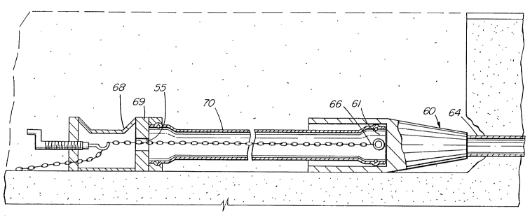
One example of another common installation
technique, pulling (indirect pushing) is illustrated
in Figures 11, 12 and 13. A pipeline replacement tool,
indicated generally as 60, surrounds the bell 61 of the
first pipe being pulled; in this case over an old
existing pipeline 64. Chain 66 attached to the back of
the tool runs inside the new pipe to a pushing head 68
immediately behind the most recently added pipe 70 in
the pipeline. As the pipeline replacement tool 60 (or a
tunnelling tool or boring machine) pulls the chain
forward, longitudinal force is applied from thrust plate
69 to end surface 55 of this most recent pipe. The
entire pipeline moves into the tunnel, as shown in
- 18 -
2(~57605
Figure 13. Pushing force is born by pipeline
identically to previous example using backhoe push,
excepting only that in this case force is applied from
thrust-plate 69 onto end 55 of the last pipe, instead of
from backhoe shovel. Thus, force moves longitudinally
through BNB couplings indicated generally as 58, and
nipples 16 are isolated and as previously described,
have no chance of damaging coupling. This indirect
pushing method was the one actually used with the
invented coupling at installations in Calgary, Alberta
and worked well.
The foregoing is by way of example, and the
invention should be limited only by the scope of the
appended claims.
-- 19 --