Language selection

Search

Patent 2058045 Summary

Third-party information liability

Some of the information on this Web page has been provided by external sources. The Government of Canada is not responsible for the accuracy, reliability or currency of the information supplied by external sources. Users wishing to rely upon this information should consult directly with the source of the information. Content provided by external sources is not subject to official languages, privacy and accessibility requirements.

Claims and Abstract availability

Any discrepancies in the text and image of the Claims and Abstract are due to differing posting times. Text of the Claims and Abstract are posted:

  • At the time the application is open to public inspection;
  • At the time of issue of the patent (grant).
(12) Patent: (11) CA 2058045
(54) English Title: EARTH REINFORCEMENT AND EMBANKMENT BUILDING SYSTEMS
(54) French Title: SYSTEMES DE CONSTRUCTION DE RENFORT ET DE TALUS DE TERRE
Status: Expired
Bibliographic Data
(51) International Patent Classification (IPC):
  • E02D 17/18 (2006.01)
  • E02D 29/02 (2006.01)
(72) Inventors :
  • MARTINEZ-GONZALEZ, HECTOR SAMUEL (Mexico)
(73) Owners :
  • MARTINEZ-GONZALEZ, HECTOR SAMUEL (Mexico)
(71) Applicants :
  • MARTINEZ-GONZALEZ, HECTOR SAMUEL (Mexico)
(74) Agent: AVENTUM IP LAW LLP
(74) Associate agent:
(45) Issued: 2003-05-27
(22) Filed Date: 1991-12-18
(41) Open to Public Inspection: 1993-06-19
Examination requested: 1998-12-09
Availability of licence: N/A
(25) Language of filing: English

Patent Cooperation Treaty (PCT): No

(30) Application Priority Data: None

Abstracts

English Abstract


This invention relates to improvement in earth reinforcement
and embankment building systems, and more specifically to a
combination of lateral slabs, that, with anchors and salients,
join trusses to which the meshes, by means of tie rods, are
holded, in order to form an internal deposit between slab
walls, in which, alternating meshes and earth, embankments
are built.


Claims

Note: Claims are shown in the official language in which they were submitted.


THE EMBODIMENTS OF THE INVENTION IN WHICH AN EXCLUSIVE PROPERTY
OR PRIVILEGE IS CLAIMED ARE DEFINED AS FOLLOWS:

1. An earth reinforcement and embankment system comprising in
combination slabs with interfitting V-shaped edges comprising
mating male members and female grooves, anchor means inside the
slabs securing a plurality of spaced apart Omega ( ) shaped
salients held in place before pouring, each salient exiting the
slab by a salient loop extending outside the slab adjacent one
surface therefor and anchored inside the slabs by engagement of
the anchor means with the salients, a set of meshes for
coupling to the salient loops, truss rods of cylindrical shape
hooked to said salient loops at one end and holding one of the
meshes at another end in such a way that the mesh can maintain
its position regardless of external tensions and internal
pressures, said truss rods being of a length between the slab
and the meshes permitting deposited earth to pass between the
meshes and slabs and to reside about the truss rods thereby
to avoid malformation of deposited earth from damaging the
meshes.

-4-

Description

Note: Descriptions are shown in the official language in which they were submitted.


20~8Q'4~
SUMMARY OF THE INVENTION
This invention relates to improvement in earth reinforcement
and embankment building systems, and more specifically to a
combination of lateral slabs, that, with anchors and salients,
join trusses to which the meshes, by means of tie rods, are
holded, in order to form an internal deposit between Slab
walls, in which, alternating meshes and earth, embankments
are built.
BACKGROUND OF THE TNVENTION
For years the construction industry, specially the one
addressed to the construction of embankments and highways has
encountered a problem in'the erosion caused first in laterals,
and then in the rest of the embankment, circumstance that
destroys the roads and highways, this problem has increased as ,
vehicles have demanded the construction of under/over passes,
or convergents at different levels than the normal level of
the land they are built on.
In the past, some experts on the subject have tried to
solve this problem using laterals and elements that work as a
resistance structure, with the purpose of avoiding the
embankment and foundation's erosion and destruction, with the
use of lateral elements and bands that are laid out between the
different filling layers, however such systems are extremely
- 1 -


~058~04~
expensive and though they support the laterals, they always
present the possibility that in time or with the humidity
excess, they could erode and might allow the laterals to
colapse; on the other hand, the cost of the known systems are
by far, superior to the cast involved in the use of the
present invention, therefore all that has been known up to
now, has not provided a permanent solution to the problem,
since eventually as result of humidity and water penetrations such
structures need to be checked and repaired, which no doubt
causes serious types of problems, as~in ahe.first'place;wthe
suspension of vehicle flow on the section of the highway that
is. being repaired at a determined moment, and the financial
cost that such repair demands.
So, the main purpose of this invention, is to provide a
system that be safe once it is set, resulting in , an advantage
to the known systems, for as it shall be shown later, the
joining of the lateral slabs and the metalic structure is so
firm that its dismeberment is impossible, on the other hand,
the new usage of a metallic anticorrosive mesh allows the
converting of the different layers of the embanlament into an
almost monolitic body with the slabs and structures, having
enough capacity to indefinitely bear the vibration load and
weight of the vehicles that pass on them. ,
BRIEF DESCRIPTION OF THE DRAWINGS
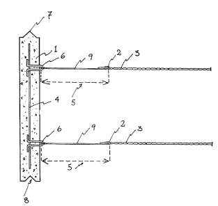
Figure 1, shows a cross sectional view of the incorporated
slabs, tie rods, and mesh.
Figure #2, shows a top view of the incorporated slabs,
tie rods, and mesh.
Figure 3, shows a side cross sectional view, of a part
of the incorporated slabs, truss and tie rods.
- 2 -


Figure 4, shows a side sectional view of the end where
the mesh joins the tie rod.
DETAILED DESCRIPTION OF THE INVENTION
In reference to said figures, this system comprises in
combination, lateral slabs (1), in each one of them there axe
two female entries, (8) and two male entries (7), which allow
the slabs (1) to be mounted axially by the insertion of the
male entry (7), in the female entry (8), this way by ._
forming walls with a combination of multiple slabs, it is
possible to incorporate enough space to receive the necessary
earth to form the required embankment; such slabs (1) are
preferable manufactured or concrete, and at the moment of the
pouring of the concrete one or several anchors are mounted in ,
their interior (4), which properly secured provide, to the salient
(6), the necessary resistance to support the tension that the
mesh's work requires.
Also the invention combines a plurality of trusses (9),
which with one of their ends hook the salient (6) and with
the other hold the mesh (3) by means of the rod (2), in such
a way that it can mantain its position regardless of the
external tensions and the internal pressures.
It has special importance the fact that the distance '
resulting of the lenght of the truss (9), between the mesh
(3) and the slabs (1), becomes an area of tolerance (5) that at
the moment the incorporation starts working, eliminating the
possibility of deformations, loosenings or even fractures that
could happen if such area of tolerance (5) was not established.
- 3 -

Representative Drawing
A single figure which represents the drawing illustrating the invention.
Administrative Status

For a clearer understanding of the status of the application/patent presented on this page, the site Disclaimer , as well as the definitions for Patent , Administrative Status , Maintenance Fee  and Payment History  should be consulted.

Administrative Status

Title Date
Forecasted Issue Date 2003-05-27
(22) Filed 1991-12-18
(41) Open to Public Inspection 1993-06-19
Examination Requested 1998-12-09
(45) Issued 2003-05-27
Expired 2011-12-18

Abandonment History

There is no abandonment history.

Payment History

Fee Type Anniversary Year Due Date Amount Paid Paid Date
Application Fee $0.00 1991-12-18
Maintenance Fee - Application - New Act 2 1993-12-20 $50.00 1993-11-26
Maintenance Fee - Application - New Act 3 1994-12-19 $50.00 1994-12-16
Maintenance Fee - Application - New Act 4 1995-12-18 $50.00 1995-12-12
Maintenance Fee - Application - New Act 5 1996-12-18 $75.00 1996-11-13
Maintenance Fee - Application - New Act 6 1997-12-18 $75.00 1997-11-17
Request for Examination $200.00 1998-12-09
Maintenance Fee - Application - New Act 7 1998-12-18 $75.00 1998-12-09
Maintenance Fee - Application - New Act 8 1999-12-20 $75.00 1999-12-15
Maintenance Fee - Application - New Act 9 2000-12-18 $75.00 2000-12-18
Maintenance Fee - Application - New Act 10 2001-12-18 $100.00 2001-12-18
Maintenance Fee - Application - New Act 11 2002-12-18 $100.00 2002-12-17
Final Fee $150.00 2003-03-17
Maintenance Fee - Patent - New Act 12 2003-12-18 $100.00 2003-12-15
Back Payment of Fees $125.00 2004-12-17
Maintenance Fee - Patent - New Act 13 2004-12-20 $125.00 2004-12-17
Maintenance Fee - Patent - New Act 14 2005-12-19 $125.00 2005-11-16
Maintenance Fee - Patent - New Act 15 2006-12-18 $225.00 2006-12-15
Maintenance Fee - Patent - New Act 16 2007-12-18 $225.00 2007-12-12
Maintenance Fee - Patent - New Act 17 2008-12-18 $225.00 2008-12-18
Maintenance Fee - Patent - New Act 18 2009-12-18 $225.00 2009-11-30
Maintenance Fee - Patent - New Act 19 2010-12-20 $225.00 2010-12-09
Owners on Record

Note: Records showing the ownership history in alphabetical order.

Current Owners on Record
MARTINEZ-GONZALEZ, HECTOR SAMUEL
Past Owners on Record
None
Past Owners that do not appear in the "Owners on Record" listing will appear in other documentation within the application.
Documents

To view selected files, please enter reCAPTCHA code :


To view images, click a link in the Document Description column. To download the documents, select one or more checkboxes in the first column and then click the "Download Selected in PDF format (Zip Archive)" or the "Download Selected as Single PDF" button.

List of published and non-published patent-specific documents on the CPD .

If you have any difficulty accessing content, you can call the Client Service Centre at 1-866-997-1936 or send them an e-mail at CIPO Client Service Centre.


Document
Description 
Date
(yyyy-mm-dd) 
Number of pages   Size of Image (KB) 
Abstract 1994-02-26 1 11
Cover Page 1994-02-26 1 14
Description 1994-02-26 3 107
Claims 1994-02-26 1 25
Cover Page 2003-04-23 1 30
Claims 2002-06-14 1 33
Drawings 1994-02-26 4 59
Representative Drawing 2002-09-05 1 6
Representative Drawing 1998-10-28 1 9
Correspondence 2003-03-17 1 37
Fees 2001-12-18 1 38
Fees 1998-12-09 1 35
Fees 2000-12-18 1 29
Prosecution-Amendment 2001-12-18 2 49
Prosecution-Amendment 2002-06-14 2 71
Assignment 1991-12-18 4 132
Prosecution-Amendment 1998-12-09 1 37
Fees 1997-11-17 1 34
Fees 1999-12-15 1 32
Fees 2004-12-17 1 65
Fees 2004-12-17 1 60
Fees 2006-12-15 1 54
Fees 1996-11-13 1 104
Fees 1995-12-12 1 102
Fees 1994-12-16 1 114
Fees 1993-11-26 1 89