Language selection

Search

Patent 2058203 Summary

Third-party information liability

Some of the information on this Web page has been provided by external sources. The Government of Canada is not responsible for the accuracy, reliability or currency of the information supplied by external sources. Users wishing to rely upon this information should consult directly with the source of the information. Content provided by external sources is not subject to official languages, privacy and accessibility requirements.

Claims and Abstract availability

Any discrepancies in the text and image of the Claims and Abstract are due to differing posting times. Text of the Claims and Abstract are posted:

  • At the time the application is open to public inspection;
  • At the time of issue of the patent (grant).
(12) Patent: (11) CA 2058203
(54) English Title: INDENTED TUBE FOR OPTICAL RIBBON
(54) French Title: TUBE DENTELE POUR RUBAN DE FIBRE OPTIQUE
Status: Expired and beyond the Period of Reversal
Bibliographic Data
(51) International Patent Classification (IPC):
  • G02B 06/44 (2006.01)
(72) Inventors :
  • MCALPINE, WARREN W. (United States of America)
  • KUNDIS, DIETER (United States of America)
(73) Owners :
  • SIECOR CORPORATION
(71) Applicants :
  • SIECOR CORPORATION (United States of America)
(74) Agent: GOWLING WLG (CANADA) LLP
(74) Associate agent:
(45) Issued: 1997-06-10
(22) Filed Date: 1991-12-20
(41) Open to Public Inspection: 1992-06-22
Examination requested: 1992-04-29
Availability of licence: N/A
Dedicated to the Public: N/A
(25) Language of filing: English

Patent Cooperation Treaty (PCT): No

(30) Application Priority Data:
Application No. Country/Territory Date
632,159 (United States of America) 1990-12-21

Abstracts

English Abstract


Disclosed is a tube holding optical fibers or optical
ribbons, the tube having indentations in its inner and outer
surfaces. The indentations are adjacent to better enable
opening of the tube to gain access to the ribbons.


Claims

Note: Claims are shown in the official language in which they were submitted.

THE EMBODIMENTS OF THE INVENTION IN WHICH AN EXCLUSIVE
PROPERTY OR PRIVILEGE IS CLAIMED ARE DEFINED AS FOLLOWS:
1. An optical cable element, comprising:
(a) a tube having a first lengthwise indentation in
its outer surface and a second lengthwise indentation in
its inner surface adjacent to the first lengthwise
indentation; and
(b) an optical waveguide within the tube.
2. An optical cable element as recited in Claim 1,
wherein the tube has a third lengthwise indentation in
its outer surface located 180° from the first lengthwise
indentation and a fourth lengthwise indentation in its
inner surface located 180° from the second lengthwise
indentation.
3. An optical cable element, comprising:
(a) a tube having a first lengthwise indentation in
its outer surface and a second lengthwise indentation in
its inner surface adjacent to the first lengthwise
indentation; and
(b) an optical waveguide ribbon within the tube.
4. An optical cable element as recited in Claim 3,
wherein the tube has a third lengthwise indentation in
its outer surface located 180° from the first lengthwise
indentation and a fourth lengthwise indentation in its
inner surface located 180° from the second lengthwise
indentation.
5. An optical cable element as recited in Claim 3,
wherein the optical waveguide ribbon is oriented such
that the second lengthwise indentation is next to the
middle of the ribbon.
6. An optical cable element as recited in Claim 4,
wherein the optical waveguide ribbon is oriented such

that the second lengthwise indentation is next to the
middle of the ribbon.
7. An optical cable element as recited in Claim 5,
wherein the optical waveguide ribbon contains an even
number of optical waveguides.
8. An optical cable element as recited in Claim 6,
wherein the optical waveguide ribbon has an even number
of optical waveguides.
9. An optical cable element as recited in Claim 7,
wherein the distance between the two middle optical
waveguides in the ribbon is greater than the distance
between any other two adjacent optical waveguides in the
ribbon.
10. An optical cable element as recited in Claim 8,
wherein the space between the two middle optical
waveguides in the ribbon is greater than the distance
between any other two adjacent optical waveguides in the
ribbon.

Description

Note: Descriptions are shown in the official language in which they were submitted.


-o~ ~ 2 0 5 8 2 0 3
BACKGROUND OF THE INVENTION
The field of the invention is that of optical
transmission cables.
Fiber optical cables have received wide acceptance
among telecommunications providers. While some optical
cables house their optical waveguides loosely within tubes,
other optical cables provide ribbons each having a plurality
of optical waveguides. Particularly in cables having a
large number of optical waveguides, ease of accessibility to
the optical waveguides is an important factor in planning
systems expected to provide service over long periods of
time during which system adjustments and individual failures
must be considered.
Many cables provide rip cords to remove a sheath
holding optical waveguides. Rip cords are difficult to
locate and use effectively if mid-span access is required.
Tube slitting or stripping tubes are also used to remove
sheaths; great caution must be exercised in their use,
because if the sheath is cut too deeply, damage to the
optical waveguides may occur. Irregularities in a cable's
cross section also must be considered when using such tools.
SUMMARY OF THE INVENTION
Addressing the problems of cable access in mid-span,
described is a tube holding an optical waveguide, the tube
having a first lengthwise indentation in its outer surface
and a second lengthwise indentation in its inner surface
adjacent to the first lengthwise indentation. The cable
tube may also have a third lengthwise indentation in its ,
outer surface located 180~ from the first lengthwise
indentation, and a fourth lengthwise indentation in its

3 20 58203
inner surface located 180 from the second lengthwise
indentation. With this arrangement, a tube slitting tool
may be used with less danger to optical waveguides within
the tube. The optical waveguide may be housed in ribbons or
ribbon stacks. In the case of optical fiber ribbons, the
ribbons may be oriented such that the inner (second and
fourth) lengthwise indentations are adjacent to the middle
of a ribbon. If this is the case, it will be advantageous
to provide the optical fiber ribbon with an even number of
optical waveguides, the distance between the two middle
optical waveguides in the ribbon being greater than the
distance between any other two adjacent optical waveguides
in the ribbon. With this arrangement, even if the ribbon is
accidentally nicked by the tube slitting tool, it may fall
within the region between the two middle optical wave-
guides, not damaging any of the optical waveguides them-
selves.
BRIEF DESCRIPTION OF THE DRAWINGS
The preferred embodiment is described with reference to
the accompanying drawings, in which:
Fig. 1 is a cross sectional view of an optical wave-
guide ribbon;
Fig. 2 is a cross sectional view of a cable element
including a stack of ribbons as shown in Fig. l;
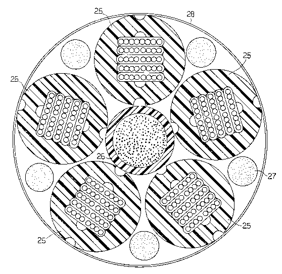
Fig. 3 is a cable core comprising a plurality of cable
elements as shown in Fig. 2;
Fig. 4 is a longitudinal sectional view of a tip and
die used in manufacture of the element shown in Fig. 2; and,
Fig. 5 is an end view of the apparatus shown in Fig. 4.

20 58203 ~
DETAILED DESCRIPTION OF THE PREFERRED EMBODIMENT
Optical waveguide ribbon 20 in Figure 1 consists of
eight optical waveguides 10 and urethane acrylate coatings
11, 12. The left four optical waveguides 10 and the right
four optical waveguides 10 receive coatings 11 in side by
side extrusions in which the right four optical waveguides
are maintained in an end to end touching relation 23 and the
left four optical waveguides are maintained in an end to end
touching relation 22. Coating 12 is then extruded over
coatings 11 in the same processing line. Since the middle
optical waveguides are separated by two layers of coating
11, the distance between them is greater than the distance
between any other two adjacent optical waveguides.
Optical cable element 25 in Figure 2 consists of
thermoplastic tube 13 circumscribing a stack of optical
waveguide ribbons 20. Tube 13 has longitudinal recesses 14,
16 in its outer surface and longitudinal recesses 15, 17 in
its inner surface, with recess 15 adjacent to recess 14 and
recess 17 adjacent to recess 16. Tube 13 can be slit
through recesses 14, 15, reducing the risk of damage to
ribbons 20. Ribbons 20 are oriented such that indentations
15, 17 are next to middle section 19 of a ribbon.
An example of a cable core having a plurality of
elements 25 is shown in Fig. 3. Within binder tape 28 are
elements 25 and waterblocking materials 27 stranded about
central glass reinforced plastic member 26.
Tube 13 may then be manufactured using the tip and die
extrusion apparatus shown in Figs. 4 and 5. Tip 31 has rod
sections 36, 37 mounted to its passage 39 and extending
through the central passage of die 30. The exterior section

- 5 20 58203
45 of tip 31 is cone shaped and its end surface 46 is flat.
Die 30 has rod sections 34, 35 mounted to its inner passage.
During processing, ribbons 20 proceed through tip interior
32 to passage 39 and molten thermoplastic 13 is extruded
through melt passage 33, surrounding ribbons 20 and rods 36,
37. Rods 36, 37 thus form recesses 15, 17. Rods 34, 35
form recesses 14, 16 when the melt proceeds through exit 38
of die 30.

Representative Drawing
A single figure which represents the drawing illustrating the invention.
Administrative Status

2024-08-01:As part of the Next Generation Patents (NGP) transition, the Canadian Patents Database (CPD) now contains a more detailed Event History, which replicates the Event Log of our new back-office solution.

Please note that "Inactive:" events refers to events no longer in use in our new back-office solution.

For a clearer understanding of the status of the application/patent presented on this page, the site Disclaimer , as well as the definitions for Patent , Event History , Maintenance Fee  and Payment History  should be consulted.

Event History

Description Date
Time Limit for Reversal Expired 2003-12-22
Letter Sent 2002-12-20
Grant by Issuance 1997-06-10
Notice of Allowance is Issued 1996-10-08
Application Published (Open to Public Inspection) 1992-06-22
All Requirements for Examination Determined Compliant 1992-04-29
Request for Examination Requirements Determined Compliant 1992-04-29

Abandonment History

There is no abandonment history.

Fee History

Fee Type Anniversary Year Due Date Paid Date
MF (patent, 6th anniv.) - standard 1997-12-22 1997-12-09
MF (patent, 7th anniv.) - standard 1998-12-21 1998-12-09
MF (patent, 8th anniv.) - standard 1999-12-20 1999-12-02
MF (patent, 9th anniv.) - standard 2000-12-20 2000-12-01
MF (patent, 10th anniv.) - standard 2001-12-20 2001-12-03
Owners on Record

Note: Records showing the ownership history in alphabetical order.

Current Owners on Record
SIECOR CORPORATION
Past Owners on Record
DIETER KUNDIS
WARREN W. MCALPINE
Past Owners that do not appear in the "Owners on Record" listing will appear in other documentation within the application.
Documents

To view selected files, please enter reCAPTCHA code :


To view images, click a link in the Document Description column. To download the documents, select one or more checkboxes in the first column and then click the "Download Selected in PDF format (Zip Archive)" or the "Download Selected as Single PDF" button.

List of published and non-published patent-specific documents on the CPD .

If you have any difficulty accessing content, you can call the Client Service Centre at 1-866-997-1936 or send them an e-mail at CIPO Client Service Centre.


Document
Description 
Date
(yyyy-mm-dd) 
Number of pages   Size of Image (KB) 
Abstract 1994-03-29 1 9
Claims 1994-03-29 2 64
Drawings 1994-03-29 3 167
Description 1994-03-29 4 136
Drawings 1997-04-09 3 152
Claims 1997-04-09 2 61
Abstract 1997-04-09 1 9
Description 1997-04-09 4 137
Representative drawing 1999-07-21 1 57
Maintenance Fee Notice 2003-01-19 1 174
Fees 1997-12-08 1 33
Fees 1996-12-04 1 68
Fees 1995-11-13 1 95
Fees 1994-10-13 1 43
Fees 1993-08-24 1 28
Courtesy - Office Letter 1992-07-13 1 20
Courtesy - Office Letter 1992-11-30 1 29
Correspondence related to formalities 1997-03-13 1 33
Courtesy - Office Letter 1992-08-27 1 37
Correspondence related to formalities 1992-12-07 1 26
Correspondence related to formalities 1992-08-18 2 51
Prosecution correspondence 1992-04-28 1 29
Prosecution correspondence 1992-10-29 1 30