Sélection de la langue

Search

Sommaire du brevet 2058203 

Énoncé de désistement de responsabilité concernant l'information provenant de tiers

Une partie des informations de ce site Web a été fournie par des sources externes. Le gouvernement du Canada n'assume aucune responsabilité concernant la précision, l'actualité ou la fiabilité des informations fournies par les sources externes. Les utilisateurs qui désirent employer cette information devraient consulter directement la source des informations. Le contenu fourni par les sources externes n'est pas assujetti aux exigences sur les langues officielles, la protection des renseignements personnels et l'accessibilité.

Disponibilité de l'Abrégé et des Revendications

L'apparition de différences dans le texte et l'image des Revendications et de l'Abrégé dépend du moment auquel le document est publié. Les textes des Revendications et de l'Abrégé sont affichés :

  • lorsque la demande peut être examinée par le public;
  • lorsque le brevet est émis (délivrance).
(12) Brevet: (11) CA 2058203
(54) Titre français: TUBE DENTELE POUR RUBAN DE FIBRE OPTIQUE
(54) Titre anglais: INDENTED TUBE FOR OPTICAL RIBBON
Statut: Périmé et au-delà du délai pour l’annulation
Données bibliographiques
(51) Classification internationale des brevets (CIB):
  • G02B 06/44 (2006.01)
(72) Inventeurs :
  • MCALPINE, WARREN W. (Etats-Unis d'Amérique)
  • KUNDIS, DIETER (Etats-Unis d'Amérique)
(73) Titulaires :
  • SIECOR CORPORATION
(71) Demandeurs :
  • SIECOR CORPORATION (Etats-Unis d'Amérique)
(74) Agent: GOWLING WLG (CANADA) LLP
(74) Co-agent:
(45) Délivré: 1997-06-10
(22) Date de dépôt: 1991-12-20
(41) Mise à la disponibilité du public: 1992-06-22
Requête d'examen: 1992-04-29
Licence disponible: S.O.
Cédé au domaine public: S.O.
(25) Langue des documents déposés: Anglais

Traité de coopération en matière de brevets (PCT): Non

(30) Données de priorité de la demande:
Numéro de la demande Pays / territoire Date
632,159 (Etats-Unis d'Amérique) 1990-12-21

Abrégés

Abrégé anglais


Disclosed is a tube holding optical fibers or optical
ribbons, the tube having indentations in its inner and outer
surfaces. The indentations are adjacent to better enable
opening of the tube to gain access to the ribbons.

Revendications

Note : Les revendications sont présentées dans la langue officielle dans laquelle elles ont été soumises.


THE EMBODIMENTS OF THE INVENTION IN WHICH AN EXCLUSIVE
PROPERTY OR PRIVILEGE IS CLAIMED ARE DEFINED AS FOLLOWS:
1. An optical cable element, comprising:
(a) a tube having a first lengthwise indentation in
its outer surface and a second lengthwise indentation in
its inner surface adjacent to the first lengthwise
indentation; and
(b) an optical waveguide within the tube.
2. An optical cable element as recited in Claim 1,
wherein the tube has a third lengthwise indentation in
its outer surface located 180° from the first lengthwise
indentation and a fourth lengthwise indentation in its
inner surface located 180° from the second lengthwise
indentation.
3. An optical cable element, comprising:
(a) a tube having a first lengthwise indentation in
its outer surface and a second lengthwise indentation in
its inner surface adjacent to the first lengthwise
indentation; and
(b) an optical waveguide ribbon within the tube.
4. An optical cable element as recited in Claim 3,
wherein the tube has a third lengthwise indentation in
its outer surface located 180° from the first lengthwise
indentation and a fourth lengthwise indentation in its
inner surface located 180° from the second lengthwise
indentation.
5. An optical cable element as recited in Claim 3,
wherein the optical waveguide ribbon is oriented such
that the second lengthwise indentation is next to the
middle of the ribbon.
6. An optical cable element as recited in Claim 4,
wherein the optical waveguide ribbon is oriented such

that the second lengthwise indentation is next to the
middle of the ribbon.
7. An optical cable element as recited in Claim 5,
wherein the optical waveguide ribbon contains an even
number of optical waveguides.
8. An optical cable element as recited in Claim 6,
wherein the optical waveguide ribbon has an even number
of optical waveguides.
9. An optical cable element as recited in Claim 7,
wherein the distance between the two middle optical
waveguides in the ribbon is greater than the distance
between any other two adjacent optical waveguides in the
ribbon.
10. An optical cable element as recited in Claim 8,
wherein the space between the two middle optical
waveguides in the ribbon is greater than the distance
between any other two adjacent optical waveguides in the
ribbon.

Description

Note : Les descriptions sont présentées dans la langue officielle dans laquelle elles ont été soumises.

-o~ ~ 2 0 5 8 2 0 3
BACKGROUND OF THE INVENTION
The field of the invention is that of optical
transmission cables.
Fiber optical cables have received wide acceptance
among telecommunications providers. While some optical
cables house their optical waveguides loosely within tubes,
other optical cables provide ribbons each having a plurality
of optical waveguides. Particularly in cables having a
large number of optical waveguides, ease of accessibility to
the optical waveguides is an important factor in planning
systems expected to provide service over long periods of
time during which system adjustments and individual failures
must be considered.
Many cables provide rip cords to remove a sheath
holding optical waveguides. Rip cords are difficult to
locate and use effectively if mid-span access is required.
Tube slitting or stripping tubes are also used to remove
sheaths; great caution must be exercised in their use,
because if the sheath is cut too deeply, damage to the
optical waveguides may occur. Irregularities in a cable's
cross section also must be considered when using such tools.
SUMMARY OF THE INVENTION
Addressing the problems of cable access in mid-span,
described is a tube holding an optical waveguide, the tube
having a first lengthwise indentation in its outer surface
and a second lengthwise indentation in its inner surface
adjacent to the first lengthwise indentation. The cable
tube may also have a third lengthwise indentation in its ,
outer surface located 180~ from the first lengthwise
indentation, and a fourth lengthwise indentation in its

3 20 58203
inner surface located 180 from the second lengthwise
indentation. With this arrangement, a tube slitting tool
may be used with less danger to optical waveguides within
the tube. The optical waveguide may be housed in ribbons or
ribbon stacks. In the case of optical fiber ribbons, the
ribbons may be oriented such that the inner (second and
fourth) lengthwise indentations are adjacent to the middle
of a ribbon. If this is the case, it will be advantageous
to provide the optical fiber ribbon with an even number of
optical waveguides, the distance between the two middle
optical waveguides in the ribbon being greater than the
distance between any other two adjacent optical waveguides
in the ribbon. With this arrangement, even if the ribbon is
accidentally nicked by the tube slitting tool, it may fall
within the region between the two middle optical wave-
guides, not damaging any of the optical waveguides them-
selves.
BRIEF DESCRIPTION OF THE DRAWINGS
The preferred embodiment is described with reference to
the accompanying drawings, in which:
Fig. 1 is a cross sectional view of an optical wave-
guide ribbon;
Fig. 2 is a cross sectional view of a cable element
including a stack of ribbons as shown in Fig. l;
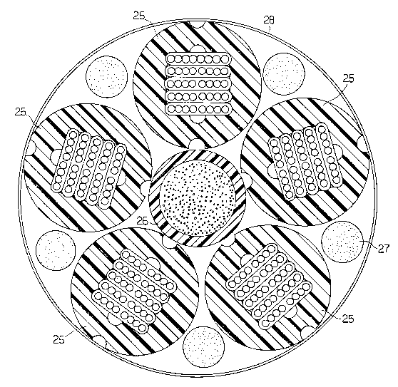
Fig. 3 is a cable core comprising a plurality of cable
elements as shown in Fig. 2;
Fig. 4 is a longitudinal sectional view of a tip and
die used in manufacture of the element shown in Fig. 2; and,
Fig. 5 is an end view of the apparatus shown in Fig. 4.

20 58203 ~
DETAILED DESCRIPTION OF THE PREFERRED EMBODIMENT
Optical waveguide ribbon 20 in Figure 1 consists of
eight optical waveguides 10 and urethane acrylate coatings
11, 12. The left four optical waveguides 10 and the right
four optical waveguides 10 receive coatings 11 in side by
side extrusions in which the right four optical waveguides
are maintained in an end to end touching relation 23 and the
left four optical waveguides are maintained in an end to end
touching relation 22. Coating 12 is then extruded over
coatings 11 in the same processing line. Since the middle
optical waveguides are separated by two layers of coating
11, the distance between them is greater than the distance
between any other two adjacent optical waveguides.
Optical cable element 25 in Figure 2 consists of
thermoplastic tube 13 circumscribing a stack of optical
waveguide ribbons 20. Tube 13 has longitudinal recesses 14,
16 in its outer surface and longitudinal recesses 15, 17 in
its inner surface, with recess 15 adjacent to recess 14 and
recess 17 adjacent to recess 16. Tube 13 can be slit
through recesses 14, 15, reducing the risk of damage to
ribbons 20. Ribbons 20 are oriented such that indentations
15, 17 are next to middle section 19 of a ribbon.
An example of a cable core having a plurality of
elements 25 is shown in Fig. 3. Within binder tape 28 are
elements 25 and waterblocking materials 27 stranded about
central glass reinforced plastic member 26.
Tube 13 may then be manufactured using the tip and die
extrusion apparatus shown in Figs. 4 and 5. Tip 31 has rod
sections 36, 37 mounted to its passage 39 and extending
through the central passage of die 30. The exterior section

- 5 20 58203
45 of tip 31 is cone shaped and its end surface 46 is flat.
Die 30 has rod sections 34, 35 mounted to its inner passage.
During processing, ribbons 20 proceed through tip interior
32 to passage 39 and molten thermoplastic 13 is extruded
through melt passage 33, surrounding ribbons 20 and rods 36,
37. Rods 36, 37 thus form recesses 15, 17. Rods 34, 35
form recesses 14, 16 when the melt proceeds through exit 38
of die 30.

Dessin représentatif
Une figure unique qui représente un dessin illustrant l'invention.
États administratifs

2024-08-01 : Dans le cadre de la transition vers les Brevets de nouvelle génération (BNG), la base de données sur les brevets canadiens (BDBC) contient désormais un Historique d'événement plus détaillé, qui reproduit le Journal des événements de notre nouvelle solution interne.

Veuillez noter que les événements débutant par « Inactive : » se réfèrent à des événements qui ne sont plus utilisés dans notre nouvelle solution interne.

Pour une meilleure compréhension de l'état de la demande ou brevet qui figure sur cette page, la rubrique Mise en garde , et les descriptions de Brevet , Historique d'événement , Taxes périodiques et Historique des paiements devraient être consultées.

Historique d'événement

Description Date
Le délai pour l'annulation est expiré 2003-12-22
Lettre envoyée 2002-12-20
Accordé par délivrance 1997-06-10
Un avis d'acceptation est envoyé 1996-10-08
Demande publiée (accessible au public) 1992-06-22
Toutes les exigences pour l'examen - jugée conforme 1992-04-29
Exigences pour une requête d'examen - jugée conforme 1992-04-29

Historique d'abandonnement

Il n'y a pas d'historique d'abandonnement

Historique des taxes

Type de taxes Anniversaire Échéance Date payée
TM (brevet, 6e anniv.) - générale 1997-12-22 1997-12-09
TM (brevet, 7e anniv.) - générale 1998-12-21 1998-12-09
TM (brevet, 8e anniv.) - générale 1999-12-20 1999-12-02
TM (brevet, 9e anniv.) - générale 2000-12-20 2000-12-01
TM (brevet, 10e anniv.) - générale 2001-12-20 2001-12-03
Titulaires au dossier

Les titulaires actuels et antérieures au dossier sont affichés en ordre alphabétique.

Titulaires actuels au dossier
SIECOR CORPORATION
Titulaires antérieures au dossier
DIETER KUNDIS
WARREN W. MCALPINE
Les propriétaires antérieurs qui ne figurent pas dans la liste des « Propriétaires au dossier » apparaîtront dans d'autres documents au dossier.
Documents

Pour visionner les fichiers sélectionnés, entrer le code reCAPTCHA :


Pour visualiser une image, cliquer sur un lien dans la colonne description du document. Pour télécharger l'image (les images), cliquer l'une ou plusieurs cases à cocher dans la première colonne et ensuite cliquer sur le bouton "Télécharger sélection en format PDF (archive Zip)" ou le bouton "Télécharger sélection (en un fichier PDF fusionné)".

Liste des documents de brevet publiés et non publiés sur la BDBC .

Si vous avez des difficultés à accéder au contenu, veuillez communiquer avec le Centre de services à la clientèle au 1-866-997-1936, ou envoyer un courriel au Centre de service à la clientèle de l'OPIC.


Description du
Document 
Date
(aaaa-mm-jj) 
Nombre de pages   Taille de l'image (Ko) 
Abrégé 1994-03-29 1 9
Revendications 1994-03-29 2 64
Dessins 1994-03-29 3 167
Description 1994-03-29 4 136
Dessins 1997-04-09 3 152
Revendications 1997-04-09 2 61
Abrégé 1997-04-09 1 9
Description 1997-04-09 4 137
Dessin représentatif 1999-07-21 1 57
Avis concernant la taxe de maintien 2003-01-19 1 174
Taxes 1997-12-08 1 33
Taxes 1996-12-04 1 68
Taxes 1995-11-13 1 95
Taxes 1994-10-13 1 43
Taxes 1993-08-24 1 28
Courtoisie - Lettre du bureau 1992-07-13 1 20
Courtoisie - Lettre du bureau 1992-11-30 1 29
Correspondance reliée aux formalités 1997-03-13 1 33
Courtoisie - Lettre du bureau 1992-08-27 1 37
Correspondance reliée aux formalités 1992-12-07 1 26
Correspondance reliée aux formalités 1992-08-18 2 51
Correspondance de la poursuite 1992-04-28 1 29
Correspondance de la poursuite 1992-10-29 1 30