Language selection

Search

Patent 2058282 Summary

Third-party information liability

Some of the information on this Web page has been provided by external sources. The Government of Canada is not responsible for the accuracy, reliability or currency of the information supplied by external sources. Users wishing to rely upon this information should consult directly with the source of the information. Content provided by external sources is not subject to official languages, privacy and accessibility requirements.

Claims and Abstract availability

Any discrepancies in the text and image of the Claims and Abstract are due to differing posting times. Text of the Claims and Abstract are posted:

  • At the time the application is open to public inspection;
  • At the time of issue of the patent (grant).
(12) Patent: (11) CA 2058282
(54) English Title: PROCESS AND AN APPARATUS FOR REMOVING WATER FROM SLAG
(54) French Title: PROCEDE ET DISPOSITIF D'ELIMINATION DE L'EAU DES SCORIES
Status: Expired
Bibliographic Data
(51) International Patent Classification (IPC):
  • B01D 17/12 (2006.01)
  • F23J 1/02 (2006.01)
(72) Inventors :
  • MARTIN, WALTER JOSEF (Germany)
  • MARTIN, JOHANNES JOSEF EDMUND (Germany)
(73) Owners :
  • MARTIN GMBH FUR UMWELT-UND ENERGIETECHNIK (Germany)
(71) Applicants :
(74) Agent: FETHERSTONHAUGH & CO.
(74) Associate agent:
(45) Issued: 1998-08-25
(22) Filed Date: 1991-12-20
(41) Open to Public Inspection: 1992-06-22
Examination requested: 1992-06-16
Availability of licence: N/A
(25) Language of filing: English

Patent Cooperation Treaty (PCT): No

(30) Application Priority Data:
Application No. Country/Territory Date
P 40 41 381.0 Germany 1990-12-21

Abstracts

English Abstract


Water is extracted from slag that has been quenched in
the water bath of a deslagger and expelled from the water bath by
means of a discharge ram through a discharge chute, by causing the
discharge chute of the deslagger to vibrate. A vibration
generator, in particular an unbalance-type generator, is attached
to the discharge chute for this purpose.


French Abstract

L'eau est extraite des crasses qui ont été éteintes au bain d'eau d'une installation de décrassage et évacuée du bain d'eau au moyen d'un mouton dans une goulotte d'évacuation qui est mise en vibration. Un générateur de vibrations, en particulier du type non équilibré, est fixé à la goulotte d'évacuation à cette fin.

Claims

Note: Claims are shown in the official language in which they were submitted.


THE EMBODIMENTS OF THE INVENTION IN WHICH AN EXCLUSIVE
PROPERTY OR PRIVILEGE IS CLAIMED ARE DEFINED AS FOLLOWS:


1. A process for removing water from slag quenched in a
water bath of a deslagger comprising the steps of:
pushing the slag out of the water bath onto a discharge
chute using a discharge ram;
vibration part of the discharge chute projecting out of
the water bath; and,
repeating said pushing and vibration steps, the water
being squeezed and vibrated from the slag on said
discharge chute.


2. The process of claim 1, wherein water is squeezed
from the slag during extrusion of the discharge ram and
vibrated from the ash during retraction of the discharge ram.


3. The process of claim 1, wherein said slag on said
discharge chute is compressed by the extrusion of the
discharge ram in combination with vibration of said part of
the discharge chute and loosened by the vibration during the
retraction of the discharge ram.


4. The process of any one of claims 1 to 3, further
comprising the step of returning the water removed from the
slag to said water bath.


5. An apparatus for extracting water from slag that has
been quenched in a water bath of a slag discharger comprising:
a discharge ram for expelling the slag from said water
bath;
a discharge chute positioned external to said water bath,
said discharging chute for receiving the slag expelled by
said discharge ram;
a vibration generator attached to said discharge chute
for vibrating said discharge chute, the slag on said
discharge chute being compressed by extension of said
discharge ram in combination with vibration of said
discharge chute and being loosened by the vibration
during retraction of the discharge ram.

6. The apparatus of claim 5, wherein said vibration
generator is an unbalanced vibration generator.


7. The apparatus of claim 5 or 6, wherein said

vibration generator is mounted beneath said discharge chute.


8. The apparatus of any one of claims 5 to 7, wherein
said discharge chute is inclined to return the water removed
from the slag to said water bath.


Description

Note: Descriptions are shown in the official language in which they were submitted.


20S8282

The present invention relates to a process for removing the water
from slag that has been quenched in the water bath of a
deslagger, this slag being removed from the water bath through a
discharge shoot by means of a discharge ram. The present
invention also relates to an apparatus for carrying out the
process.


In furnaces, the fuel that has been burned moves through a slag
shaft into a deslagger that is filled with water and which
incorporates a discharge chute that is curved in an arc shape and
a discharge ram that can move back and forth and which moves slag
that has been quenched in the water bath from said water bath to
the outside through the upwardly inclined discharge chute (see,
for example, DE-OS 25 39 615).


Because the slag is quenched with water it is, of necessity,
completely saturated with water which causes problems with regard
to its disposal or if it is to be subjected to further
processing. One of the problems lies in the fact that the water
that adheres to the slag is in part released during subsequent
transportation. This can lead to the undesirable escape of water
from the means of transport and, because of the fact that this
water contains harmful substances, it can contribute to
environmental pollution or to pollution of the ground water.
Another significant problem lies in the fact that because of the
water that it contains, the slag is correspondingly heavier,


which leads to a considerable lncrease in transportation and
dumping costs.
It is the task of the present invention to permit
the extensive removal of water from slag that originates from
a furnace and to do this in the simplest possible manner
without any additional cost-lntenslve plant.
As embodied and broadly described herein, the
invention provldes a process for removing water from slag
quenched ln a water bath of a deslagger compris~ng the steps
of pushing the slag out of the water bath onto a dlscharge
chute using a discharge ram; vibratlon part of the discharge
chute pro~ecting out of the water bath; and, repeating said
pushing and vibration steps, the water being squeezed and
vibrated from the slag on sald dlscharge chute.
As embodied and broadly described herein, the
invention further provides an apparatus for extractlng water
from slag that has been quenched in a water bath of a slag
discharger comprlslng: a discharge ram for expelling the slag
from said water bath; a dlscharge chute positioned external to
said water bath, sald discharging chute for receiving the slag
expelled by said discharge ram; a vibratlon generator attached
to said discharge chute for vibrating sald dlscharge chute,
the slag on said dlscharge chute being compressed by extenslon

of said discharge ram in combination with vibration of sald
discharge chute and being loosened by the vibration during
retraction of the dlscharge ram.


r~
25986-19

- ~ 58 ~
2a
the discharge ram.
Proceedlng from the process of the type described in
the introduction hereto, according to the present invention
this task has been solved in that the discharge chute of the
deslagger is caused to vibrate. Particularly good results are
achieved if, in a further development of the present
inventlon, the area of the dlscharge chute that ls free of
water ls caused to vlbrate. ~ecause of the generatlon of thls
vibratlon, whlch ls transferred from the dlscharge chute to
the slag that ls withln the chute, a large quantlty of water
ls extracted from the slag which, after processing accordlng
to the present invention, has a water content of approximately
12%, whereas slag that leaves the deslagger without belng
processed according to the present inventlon has a water
content of approxlmately 18 to 22%. This means that a
conslderable quantlty of water has been extracted, which
greatly reduces the consumption of fresh water or additional
process water. The slag that is obtained after thls process
feels llke damp earth and has no more drops of water adherlng
to lt.


25986-19

20~8282


In order to carry out this process, it is sufficient if,
according to the present invention, a vibration generator, in
particular an unbalance-type generator, is installed on the
discharge chute. This leads to a particularly simple system for
carrying out the process for, apart from the installation of the
vibration generator, no modifications need be made to the
existing deslagger, so that the existing deslagger can be
retrofitted in a particularly simple manner.


It has been shown to be advantageous if the vibration generator,
particularly an unbalance-type generator, is installed on the
bottom of the discharge chute.


The best results with respect to extracting the water have been
achieved in that the vibrating generator, in particular an
unbalance-type generator, is installed at the border between that
section of the discharge chute that is filled with water and the
section of the discharge chute that contains no water, and is
connected to this.


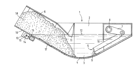
The present invention will be described in greater detail below
on the basis of an embodiment shown in the drawings appended

hereto. These drawings, which consist of a single figure, show a
partial longitudinal section through a deslagger.


4 2058282
The slag that originates in a fire grate (not shown herein) falls
into the slag drop shaft 2 of a deslagger 1. The slag drop shaft
2 opens out into a curved pan 3, on the bottom 4 of which a
discharge ram 5 can move back and forth. During each ~troke, the
discharge ram 5 moves the slag that is resting on the bottom 4
into the discharge chute 6, from which the slag finally moves
into the open.


At its rear end, the discharge ram 5 is articulated onto one or a
plurality of cranks 7 that are rigidly attached to a shaft 8
which, in its turn, is connected to a drive system (not shown
herein).


The discharge ram 5 incorporates a face surface 9 that is
essentially perpendicular to the bottom surface 4 of the base pan
3 and serves to expel the slag. In the embodiment shown, the
discharge ram 5 incorporates a step 10 that exerts an additional
discharge effect.


The front upper area of the discharge chute 6 is defined by a
rounded edge 11 that extends into the water bath that is located
in the curved pan 3 in order to ensure an air-tight fit of the
slag drop shaft, because there is a negative pressure in the
furnace fire box. The water level is numbered 12.


205828~


The slag that is quenched in the water bath within the curved pan
3 is pushed into the discharge chute 6 that rises obliquely by
the face surface 9 of the ram and by the additional step 10,
where it emerges from the surface of the water as a compact mass.
At this point, water that is adhering to the outside of the slag
can flow back into the water bath.


In order to achieve a particularly high level of extraction of
the water from the slag that emerges from the discharge chute 6,
on the bottom of th~ discharge chute there is a vibration
generator in the form of an unbalanced-type generator 13, and
this supports a weight 15 on a driven shaft 14; this causes the
whole of the discharge chute to vibrate. These vibrations are
transferred to the slag and to the water that is adhering to the
slag, and this causes the extraction of a large quantity of water
from the slag. When this occurs, the water that has been
extracted flows back into the water bath so that, a~art ~o~ t~
installation of a vibration generator, no other modifications
need be undertaken and no additional systems have to be
installed. In the preferred embodiment that is shown, the
vibration generator 13 is rigidly attached at the border,
numbered 16, between the water-filled portion 17 and the water-
free section 18 of the discharge chute, to the bottom 19 of the
discharge chute, so that the vibrations are transferred to the
whole of the discharge chute and thus to the slag.


Representative Drawing
A single figure which represents the drawing illustrating the invention.
Administrative Status

For a clearer understanding of the status of the application/patent presented on this page, the site Disclaimer , as well as the definitions for Patent , Administrative Status , Maintenance Fee  and Payment History  should be consulted.

Administrative Status

Title Date
Forecasted Issue Date 1998-08-25
(22) Filed 1991-12-20
Examination Requested 1992-06-16
(41) Open to Public Inspection 1992-06-22
(45) Issued 1998-08-25
Expired 2011-12-20

Abandonment History

There is no abandonment history.

Payment History

Fee Type Anniversary Year Due Date Amount Paid Paid Date
Application Fee $0.00 1991-12-20
Registration of a document - section 124 $0.00 1993-05-18
Maintenance Fee - Application - New Act 2 1993-12-20 $50.00 1993-08-03
Maintenance Fee - Application - New Act 3 1994-12-20 $50.00 1994-07-19
Maintenance Fee - Application - New Act 4 1995-12-20 $50.00 1995-07-31
Maintenance Fee - Application - New Act 5 1996-12-20 $75.00 1996-07-05
Maintenance Fee - Application - New Act 6 1997-12-22 $150.00 1997-07-08
Final Fee $150.00 1998-04-20
Maintenance Fee - Application - New Act 7 1998-12-21 $150.00 1998-08-13
Maintenance Fee - Patent - New Act 8 1999-12-20 $150.00 1999-07-29
Maintenance Fee - Patent - New Act 9 2000-12-20 $150.00 2000-07-26
Maintenance Fee - Patent - New Act 10 2001-12-20 $200.00 2001-07-04
Maintenance Fee - Patent - New Act 11 2002-12-20 $200.00 2002-07-16
Maintenance Fee - Patent - New Act 12 2003-12-22 $200.00 2003-07-08
Maintenance Fee - Patent - New Act 13 2004-12-20 $250.00 2004-11-17
Maintenance Fee - Patent - New Act 14 2005-12-20 $250.00 2005-11-23
Maintenance Fee - Patent - New Act 15 2006-12-20 $450.00 2006-12-13
Maintenance Fee - Patent - New Act 16 2007-12-20 $650.00 2008-01-23
Maintenance Fee - Patent - New Act 17 2008-12-22 $450.00 2008-11-20
Maintenance Fee - Patent - New Act 18 2009-12-21 $450.00 2009-12-04
Maintenance Fee - Patent - New Act 19 2010-12-20 $450.00 2010-12-09
Owners on Record

Note: Records showing the ownership history in alphabetical order.

Current Owners on Record
MARTIN GMBH FUR UMWELT-UND ENERGIETECHNIK
Past Owners on Record
MARTIN, JOHANNES JOSEF EDMUND
MARTIN, WALTER JOSEF
Past Owners that do not appear in the "Owners on Record" listing will appear in other documentation within the application.
Documents

To view selected files, please enter reCAPTCHA code :


To view images, click a link in the Document Description column. To download the documents, select one or more checkboxes in the first column and then click the "Download Selected in PDF format (Zip Archive)" or the "Download Selected as Single PDF" button.

List of published and non-published patent-specific documents on the CPD .

If you have any difficulty accessing content, you can call the Client Service Centre at 1-866-997-1936 or send them an e-mail at CIPO Client Service Centre.


Document
Description 
Date
(yyyy-mm-dd) 
Number of pages   Size of Image (KB) 
Cover Page 1994-01-29 1 17
Claims 1994-01-29 1 31
Representative Drawing 1998-08-13 1 14
Abstract 1994-01-29 1 10
Drawings 1994-01-29 1 25
Description 1994-01-29 5 173
Cover Page 1998-08-13 1 42
Description 1998-02-04 6 211
Claims 1998-02-04 2 61
Correspondence 1998-04-20 1 42
Prosecution Correspondence 1993-02-25 3 76
Prosecution Correspondence 1992-06-16 2 41
Prosecution Correspondence 1997-09-23 4 184
Examiner Requisition 1997-07-09 2 85
Office Letter 1992-07-24 1 51
Office Letter 1992-11-05 1 39
Fees 1996-07-05 1 68
Fees 1995-07-31 1 46
Fees 1994-07-19 1 56
Fees 1993-08-03 1 32