Note: Descriptions are shown in the official language in which they were submitted.
~8~
.
V~VIC~ ~OR ~LB~T~OA~ T~ A~P~ AT~o~
OF ~ ~RIN~B~ ~RU~g~ ~IT~ A ~LPIBaB
~ he invention relate~ ~o a d~ice ~or
el~ctroacou~tlcally amplifyin~ a str~nged in~rument
with a tailpieae button and with a ~ound pick-up devi~e
~t~ac~od to th~ strlnged instrument by mean6 o~ a
mountlng ~upport, wh~reby the ~ound piGX-up device ~
suitable for conneotion to an amplifier vla lead wlres
that ~un through the hollow f~r~d tailpiece bu~ton.
~p ~ntil now, to facilitate the dlrect
QlectxoaGoustia a~pli~ic~tlon o~ ~ violln, for example,
a microphon~ h~d to be provlsionally attac~d to ~he
tailplec~ in the vicinlty of th~ violin'~ ~rldge.
Occasionally, could ~hieve th~ de~ired ele~troac4us~ic
sound aMpliPication ~or ~r~n~e~ ln~trum~Dt~ u~lng ~ch
customa~y alip-on ~icrophone~. This type of dir~ct
~ound ~p~ a ion ls ~e~imes nece~s~ry, partiçularly
to promote studio ef~ctæ or Por conc~rt~ held under
un~avorable ac~us~ical ~ndltion~, ~uch a~ open a~r
: concerts.
Howev~r, th~ d~nger wlth thi~ known device is that
~;~ZO during lntenssly ~oving pl~y, the con~igu~tion ~n be
~ouched ~r evsn pu~hed o~ Moreover, the tonal ra&ult
i~ unsatlafa~tory ~ince out~id~ in~lu~nce~ ~uch a~
nois~- ~rom the b~w or the ~usi~ian' ~ breath ~a~ o be
- ampllfied to a~ unde ir~d d~re~. In addition, the
~ ZS deviae represent~ an unwant~d foreign body, whi~h -
:
. 1.
4 ~ ~
beside~ the fact that it is optically di~tur~inq - can
inhibl~ the mu~lcian ln hi~ artl8tic d~vslopment.
A device whloh ~void~ th~ prevlou~ly mentioned
di~ad~anta~es 1~ known ~rom the German P~tent 966 106.
A hollow tallplece ~ut.ton Por a ~tringed inst~ument is
de~cribed therein, throu~h which lead wire~ run to a
~ound pick-up deviae. This public~tion make~ no mention
of where this ~ound pi~k up devioe has to be ~ounted in
or on the 6tringed in~trument nor o~ the ~eah~ required
lo to fl~t4ch thls device t~re. HOWRVer~ ~v~n the question
o~ the mounting support i~ a problem th~t need~ be
optimally ~olved in order not to $nter~ere wit~ the
acou~tio patt~rn o~ the strin~2d in~trumen~.
~herefore, the ob~ect of the invention i3 to
~u~ther develop the known device i~ a way which will
allow the sound plck-up de~ice to be atta~hed in an
extremely ~i~ple way ~e a strin~ed instrument. ~n~ther
o~jectlve consi~t~ in ~peGifylng a device which can be
removed a~aln ~rom ~he ~tringed instrument with only
little ~anipul~tlon.
This ob~e~ive i8 solved in hat the sound p~ck-up
d~vice ie ~ ~lcrophone, and th~t thl~ ~icrophone i~
arr~nged ins~de th~ body of the ~ringed ln~tr~m~n~ and
i~ suppor~e~ ~y t~e hollow ~ailpi~c~ button.
~urth~r de~elopment~ o~ the lnv~ntion con~tltuta
~he ub~ea~ ~atter of ~he dependent c~
; The lnv~ntion tak~s ~dvantag~ in p~icular o~ the
f~ct khat ~ tnilpiec~ button 1~ provided anyWAy in
`~ ~t~ ged in~t~u~ents. Thi~ t~ilpieco button i~ u~d in
~trlnged ln~trum~n~ ~o attach the tailpiec~ cord.
~e~ on ~hls reAlizAtl~n, ~he invention propos~
repl~oing this custom~ry tallplece button wlth ~ hollow
~8~
tailpiec~ ~utton, wh~ch ~er~es at th~ me ti-ne A~l a
mountinq BUpport f ~r A ~lcrophone to be lntrod~oed
inside the body of the atrln~ed in~trument. Th~
microphone arranq~d in the hollo~ ta~1p~ece but~on aan
5 ~e r~ov~d at ~ny tlm~ d the t~en remainin~ hollow
~paae can be reylacod by a dummy plug, for examp1e.
Impo~tant advanta~es o~ the device according to the
inven~ion 11e in that
1) - th~ quallty ~ the amp11ficatlon i~ improved d~e to
the hlghQr ~on1c pres~ure lnsid~ the ~tringed
in~rumen~;
2) - the charac~eristio sound of the ~trlngad lnstru~ent
1~ optima11y heard ~o its he~t advanta~e;
3~ - external noi6e inf1~ences are 1arge1y e11minat~d
due t~ the arrnngement of the mic~opho~e i~lde the
body of the ~tring~d instrument;
: 4 ) - the unwanted e1e~troacousti~ ~eedback 1~ ~volded;
5) - at the ~a~e ti~e, the microphone is Arranged so
that is optl~al1y protected ln the ~tringed
instrument;
6) - wit~ ~he Rxaeption of the c~le connection WhiCh 16
conditional upon ~he ~y~tem, ln other word~ the
e1ec~rica1 lead wire runnlng to ~he amplifler, the
player ~s no 10nger l~pe~ed.
he invention ~;h~ e clarl~i~d in the following
on the b~sis o~ ~n exen~plif 1 ~d e~bodiment in conrleGtion
W~th tllree Figure~ for appliça~ion in a ~lolin.
However~ the in~ention i~ not re~tricted to violln~. On
the contr~ry, the inventlc~n can be appli~d to ~ yp~s3
30 of ~trin~d instrum~nts, w~ich ln any ca ~ ~lr~ady ha~e
a tailpi~¢e b~tton. In ~ c~llo, ~o~ exampl~, this 1~ ~n
end-pin .
~ 3;
.
_ L I I L L~ L' ~ ~ ~_ 7' ~ v ~ f ~ . 7' 1
.
In detail, the Figure~ depic~:
FIG ~ t ~xempli~led em~odim~nt of a devicR
~a~ordlng to ~he invention in a top vi~w o~
the ~ody oE a vl~lln whiah is open ~o the top;
FI~ 2 a ~ide view of the devic~ ~cording to the
invention in an in talled ~tate; ~nd
FIG 3 possible BpeC~ia embodi~an~ ~or a hollow
t~ilpl~c~ button, a dummy plug ~nd a
microphone plug with a microphone.
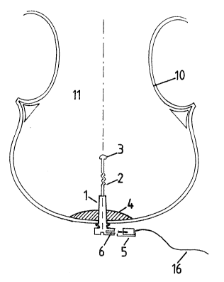
~ first exempll~ied e~bodiment o~ a device
ac~ording ~o th~ ~nvention is depicted in FIG 1 in the
top view o~ ~he body 10 o~ a violln op~n to the top.
The tailpiece button that is provid~d ln ~ny sa~e on
e~ch ~iolin i~ now replaced by a mountin~ 6upport, whlch
15 is ~esig~ed as a ~llow ta~lpiece ~ut~on 1. This
conically tap~red inn~x part of the tailplecs button
fit~ in this ex~mple in the ~h~t of t~a bloa~ 4 whlch
i6 customary in violin6. A microphone 3 1~ held by the
hollow tailpie~e b~tton 1, pr~er~bly ~y way o~ a
flexible attachment ~. Th~ ~icrophona 3 1~ arr~ngad
thereby in~ide the body of the ~oli~ ~1. A deta~habl~
oonnoction i~ pr~er~ly pr~vid~d a~ ~he ~nd of th~
ho110w tailpie~ button ~lt~ated opposlte th~ mlcrophonR
3 . ~y mean~ oP t~i3 det~chab1e conn8ction, ls~d wireS
~5 16 runninq ~o ~e amplifier are a~le to be ~on~ect~d to
the miarophone. In thi~ exe~plifiad embodimen~, th~
detachabl~ connec~ion i8 con~i~ured as a plug c~nneator
`: 5 And soske 6 d~igned at one end or th~ 1ead wire~ 1
and ~ounte~ on the ~nd o the ho110w k~ilpiece but~on
oppoaing the mi~rophone 3. The plU~ eonnector 5 and
~ocket ~ prsferably ~xhibit a b~yonet l~ck.
f
~J
.
.
.
. - , .
2~8~
. 1 1 . , ~ ., . . " ,,, i,
~ IG 2 depicts t~e sid~ vlew of the device ~ccording
to the invention belonglng to FIG l. ~he already known
referencQ symbol~ ~re ~till u~ed ~or the same par~.
Sin~ c~rdlng to the inv~ntion, the hollow tailplece
button l h~ th~ dimen~lon~ o~ the tailpiece button uaed
anyw~y in vlolins, one can ea~i1y atta~l the tallpleoe
aord 7 ~omin~ from the tailpi~o,e 8 to th~ hollow
tailpi~e button l. For this purpose, th~ h~llow
tailpiece button 1, ln the same WAy ~ ~he tailpiece
button that i8 c~l~tom~r~ in any case, exhibit~ an
annular rece~ 17, around w~ich the tAllplece cord 7 i8
wrapped to secure the tAilplece~ The hollow tailpiec~
button 1 i clamped in the shaft of the block 4.
A particularly preferred 3pe~i~ic embodl~ent o~ ~he
holl~w tailplece button 1 is ~own in FIG 3. Th~
hollow tallpiec~ button l now likewise exhi~1tR the
di~n~ions o a tailplec~ button QX~ ~ting anyway ln
v~olins. The hollow tailpiece button 1 has a
oylindrical openlng, now addi~lonally wi~h an int~rnal
2~ ~crew thread, into whlch the dummy plug ~2 hown in FIG
3b or the m~crophone plu~ 14 ~hown in FIs 3c, together
with th~ ml~rophons 3, can be ~crew~d into plac~. The
dummy plug l~ uited for b~ng screwed into the
: hollow tailpiece button 1. For this, the dummy plug 12
featur~ an ~x~ernal thread 15. Thi~ dummy plug 12 i~
scr~wed into the hollow tallpiece button 1, when no
electro~oousti¢ ~pli~ication o~ the viol~n iæ to ta~e
pl~ce O
I~ FIG 3c, on the other h~nd, th~ already deficribad
microph~ne 3 i~ now ~hown moun~.e~ 1n a ~icrophone plug
14. The m~rophon~ plug 1~ re6emble6 the dummy plug 12
and is liXewi~e pxovided wlth ~n ex~ernal thread 1~.
The ~icrophone 3 ls suitable ~r connection via a lead
wire 16 to an elea~ri~al ampllrlar. The laad wire 16
run~ via an opening 18 through the m~rophone plug 14 to
.. . .
L' L . ~ L -t 7' ~ ~ J ~ ; 4 ~
the microphone 3~ I~ the tonas ~ the vlolln ar~
~uppo~ed to ~e electroacoU~lCally ~plified, thls
microphon~ plug 14 1~; scr~w~d ~oge~h~r with th~
miorophon~ 3 Lnto the hollow tallpie~e button 1. The
microphone 3 i8 thU~ situA~ed inside the body o~ the
strin~ed instrument.
In~tead ~ a ~cre~ aonnectlon between the hollow
tallp~ece button ~nd t~ dummy plug ~2 or rather the
microphone plug 14, a clamp~d ~oint can lik~wi.se be
provided~ The hollow tallpiece bu~tcn 1, the dummy plug
12 and the mic~ophone plug ~4 ar~ pref~rably ~ormed fro~
aluminum and, in particul~r, black~anodized.
The aanstruction o~ ~he hollow tailpiece button 1,
the dummy plug 12 and the ~icrophone plu~ 14 depicted in
FIG 3 ~ake~ lt posslble ~or the hollow tailpiece ~utton
1 to b~ inetalled in the ~tringed in~trument onc~. This
hollow tailpiece button 1 can then alway~ remain in the
strlng~d ln~trument. The mlcrophone 3 is support~d by a
microphona plug 14 simil~r to the du~my plu~ 12. Th~
only dlf~erence that remains ln the in~tall~tion o~ this
microphon~ plug 14 in the hollow tailpiece. Putton 1
co~pared to th~ tailpieae ~utton~ ~ound ~nyway ln
~ringed instrum2nts ~ th~ l~ad wir~ 1~ runnlng to the
el~c~ricsl a~pli~ier. When no a~plipica~lon i3 deælr~d,
~5 the openlng in ~he hollow tailpiece but~on 1 can then be
sealed by mean~ of the du~y plug 1~, so ~hat thl6 new
hollow tRllpie~e button 1 do~s not differ ~ro~ a
conventional t~ilp~ese button~
The l~pbrt~n~ ~dvanta~es of ~uch a de~ign of th~
hollow tailpiece button 1, th~ dummy plug ~2 ~nd the
m~crophone plug 14 oonsi~t ~n tha~ ~ach ~tringed
in~trument mus~ ~nly b~ reequipped one ~lnql~ tl~e, the
microphone 3 can be installed ~nd removed very ~uickly,
:. ~ . :, . . . .
- : : ... .
:, , . . . .. ~ .: ...
: , ' '~ ' ''' ~'
' ~ : ' ,
. ., - ' '
.
.
and dl~ferent types of ~i~rophone~ ~n be u~ed at any
tl~e.
In c~nalu~ion, re~er~nca i~ al~o made to the ~act
~h~t ~ microphone, which can lupp~r~ its~lf in the
hollow tallpi~c~ button 1, can al~o b~ used of cour~e in
place o~ ~ho ~icrophon~ plu~ ~4. For this purpo~e, ths
~icrop~one ~s~ effectively pro~id~d with ~n
ext*rnal thread and bl~ck anodl~ed. In plac~ of a screw
conneotion, a olamped jo~nt ~an al~o be pro~ided.
; ~o It turn~ out that sn optl~um ~ound x~sult L~
achieve~ wh~n the ~lc~ophone 1B supported 3 - 10 ~,
pre~rably 5 ~m ~rom the end o~ the hollow tailpiece
button.
A transmitting ~n~t can al~o be u6sd ~5 ~n
a~plifier ~or wirele3~ tran~mi;3sion.
~hi~ ~y~em i~ ~en~rally appli~able to all ~trlng~d
in~trument.3 that come ~qulpped with a ~ailpiece button
3 or that ~an b~ equipped with uch a t~ilpiece button.
: :