Note: Descriptions are shown in the official language in which they were submitted.
ca2058490
CRYOGENIC PROCESS FOR THE SEPARATION OF AIR
TO PRODUCE THE ULTRA HIGH PURITY NITROGEN
TECHNICAL FIELD OF THE INVENTION
This invention relates to cryogenic process for the separation of air for recovering
ultra high purity nitrogen with high nitrogen recovery.
BACKGROUND OF THE INVENTION
Numerous processes are known for the separation of air into its constituent
components by cryogenic disi'" lion. Typically, an air separation process involves removal
of contaminant materials such as carbon dioxide and water from a compressed air stream
prior to cooling to near its dew point. The cooled air then is cryogenically distilled in an
integrated multi-column distillation system producing oxygen, nitrogen, and argon. One
type of distillation system employs a high pressure column, a low pressure column and,
optionally, a side arm column for the separation of argon. The side arm column for the
separation of argon typically communicates with the low pressure column in that an
argon/oxygen stream containing about 8-12% argon is removed and cryogenically distilled.
Variations on the above processes to produce an ultra high purity nitrogen stream
containing volatile or light contaminants, such as hydrogen, helium and neon have been
proposed. Concentration of some of these contaminants in the feed air can be as high as
20 ppm. Almost all of these light components show up in final nitrogen product from an air
separation unit (ASU). In some cases, such as for the electronic industry, this
contamination level is unacceptable in the end use of this~nitrogen product. Ultra high
purity nitrogen processes reduce the level of impurities to less than 5 ppm and typically less
than 0.1 ppm contaminants.
The following patents disclose approaches to the problem.
U.S. Patent 4,824,453 ~liscloses a process for producing ultra high purity oxygen as
well as high purity nitrogen, where the nitrogen purity exceeds 99.998% and the amount of
impurities is generally less than 10 ppm. More specifically, air is compressed, cooled and
distilled in a
CA20584~0
rectification system wherein a first stage rectification an oxygen enriched fraction is
removed from the bottom and a nilrogen rich liquid fraction is removed from an upper
portion of the first stage rectification. The nitrogen rich liquid is sub-cooled and returned as
reflux to the top of the second stage rectification. A nitrogen rich liquid is removed from an
upper portion of the second stage and nitrogen vapor removed from the second stage
rectification at a point above the liquid removal point. Liquid oxygen from the bottom of
the first stage is sub-cooled, expanded and used to drive a boiler/condenser in the top of a
high purity argon column. Nitrogen vapor from the top of the first stage is used to drive a
boiler/condenser in the bottom of a high purity oxygen coiumn. To enhance product purity,
a portion of the gaseous nitrogen stream from the top of the high pressure column rich in
impurities is removed as purge.
U.S. 4,902,321 discloses a process for producing ultra high purity nitrogen in amulti-column system. Air is compressed, cooled and charged to a high pressure column
where it is separated into its own components generating an oxygen liquid at the bottom
and a nitrogen rich vapor at the top. The oxygen liquid is expanded and used to drive a
boiler/condenser which is thermally linked to the top of the high pressure column for
condensing the nitrogen rich vapor. A portion of the nitrogen rich vapor is removed from
the top of the high pressure column and condensed in the tube side of a heat exchanger
which is operated as a reflux condenser. The resulting liquid nitrogen is expanded and
2 0 charged to the top of a stripping column wherein nitrogen, including impurities, are flashed
from the stripping column. Any impurities not removed by flashing are stripped by passing
a stream of substantially pure nitrogen upwardly through the column. The nitrogen liquid
collected at the bottom of the stripping column is pumped to the shell side of the heat
exchanger, vaporized against the nitrogen-rich vapor and removed as high purity product.
European Patent 0 0376 465 ~iscloses an air separation process for producing ultra
high purity nitrogen product. In the process, nitrogen product from a conventional air
separation process is charged to the bottom of a column equipped with a reflux condenser.
Liquid nitrogen is withdrawn from an upper portion of the column and flashed generating a
liquid and a vapor. The liquid obtained after flashing is then flashed a second time and the
resulting liquid recovered.
CA2058490
-- 3
There are essentially two problems associated with the processes described for
producing ultra-high purity nitrogen and these problems relate to the fact that in the '453
disclosure nitrogen purities are quite often not sufficiently high to meet industry
specifications and in the '321 process nitrogen recoveries are low.
SUMMARY OF THE INVENTION
This invention relates to an air separation process for producing ultra high purity
nitrogen with high nitrogen recovery. In the basic cryogenic process for the separation of
air which comprises nitrogen, oxygen and condensible and volatile impurities, an air stream
is co",pressed, freed of the condensible impurities, and cooled generating a feed for a
integrated multi-column cryogenic Ji;,i 'l, Iion system. In the integrated multi-column
distillation system, nitrogen is recovered as a product. The improvement in this basic
process for producing ultra high purity nitrogen at high nitrogen recovery in a integrated
multi-column distillation system comprising a first column and an ultra high purity nitrogen
column comprises:
a) generating a nitrogen rich vapor fraction containing volatile impurities near the
top of said first column and a crude liquid oxygen fraction at the bottom of said first
column;
b) removing a nitrogen rich vapor fraction from a top section within said first
column;
c) introducing at least a portion of that nitrogen rich vapor from said first column to
said ultra high purity nitrogen column as a feed;
d) generating a nitrogen rich vapor fraction near the top of said ultra high purity
nitrogen column and an ultra high purity liquid nitrogen fraction in a lower portion of said
ultra high purity nitrogen column;
e) partially condensing at least one of said nitrogen rich vapor fractions generated in
step a) or d) or both thereby forming a condensed fraction and an uncondensed fraction rich
in volatile impurities;
f) removing at least a portion of at least one of the uncondensed fractions rich in
volatile impurities as a purge stream;
3 0 9) returning at least a portion of at least one of the condensed fractions generated
in step (e) to at least one of the columns as reflux;
CA2058490
h) removing a crude oxygen fraction from the bottom portion of said first column;
and,
i) removing an ultra high purity nitrogen fraction as product from the ultra high
purity nitrogen column.
Significant advantages for obtaining ultra high purity nitrogen at high recovery are
achieved by concentrating volatile impurities in purge streams and minimizing the volume of
these purge streams at strategic locations in the process. The processes of this invention
permit one to recover product nitrogen at a high recovery rate; generate ultra high purity
nitrogen at inlet air supply pressure, to coproduce oxygen and the ability to control levels of
ultra high purity nitrogen and standard nitrogen produced by the plant.
DRAWINGS
Figure 1 is a schematic representation of an embodiment for generating ultra high
purity nitrogen with enhanced nitrogen recovery.
Figure 2 is a schematic representation of a variation of the process in Figure 1wherein ultra high purity nitrogen is produced at air inlet supply pressure, and there is an
ability to control the level of ultra high purity and standard purity nitrogen produced.
Figure 3 is a schematic representation of a variation of the process of Figure 1wherein large quantities of ultra high purity nitrogen are produced.
Figure 4 is a schematic representation of a variation of Figure 1 in the ultra high
purity nitrogen and oxygen are produced.
Figure 5 is a schematic representation for generating ultra high purity nitrogen and
oxygen.
DETAILED DESCRIPTION OF THE INVENTION
To facilitate an understanding of the invention and the concepts for generating an
ultra high purity nitrogen product having a volatile impurity content of less than 5 ppm and
preferably less than 0.1 ppm, reference is made to Figure 1. More particularly, a feed air
stream 1 10 is initially prepared from an air stream by compressing an air stream comprising
oxygen,
CA2058490
nitrogen, argon, volatile impurities such as hydro~en, neon, helium, and the like, and
condensible impurities, such as, carbon dioxide and water in a multi-stage compressor
system to a pressure ranging from about 80 to 300 psia and typically in the range of 90-
180 psia. These volatile impurities have a much lower boiling point than nitrogen. This
co",pressed air stream is cooled with cooling water and chilled against a refrigerant and
then passed through a molecular sieve bed to free it of condensible water and carbon
dioxide impurities.
The integrated multi-column distillation system cor"prises a first column 602 and an
ultra high purity nitrogen column 604. First column 602 typically is operated at a pressure
close to the pressure of feed air stream 110, e.g., 80 to 300 psia and air is separated into
its components by intimate contact of the vapor and liquid in the column. First column 602
is equipped with distillation trays or packing, either medium being suited for effecting
liquid/vapor contact. A high pressure nitrogen vapor stream containing volatile impurities is
generated at the top portion of first column 602 and a crude liquid oxygen stream is
generated at the bottom of first column 602.
Ultra high purity nitrogen column 604 is operated within a pressure range from
about 15-300 psia and preferably in the range of about 10 to 55 psia lower than the
pressure in first column 602 in order to produce an ultra high purity nitrogen product. The
objective in the ultra high purity nitrogen column is to provide ultra high purity nitrogen
generally in a lower section of ultra high purity nitrogen column 604 with minimal loss.
Ultra high purity nitrogen column 604 is equipped with vapor liquid contact medium which
comprises distillation trays or packing.
In the process of Figure 1, stream 110, which is free of condensible impurities and
cooled to near its dew point in a main heat exchanger system (not shown), forms the feed
to first column 602 associated with the integrated multi-column distillation system. A high
pressure nitrogen rich vapor coni , ,9 volatile impurities is generated as a overhead and a
liquid oxygen fraction as a bottoms fraction. A portion of the high pressure nitrogen vapor
generated in first column 602 is withdrawn via line 112 and substantially all of its
condensed in boiler/condenser 608 shown
CA2058490
-- 6
in the lower portion of ultra high purity nitrogen column 604. Condensation of the nitrogen
rich vapor containing impurities provides boil-up and the partial condensation of the nitrogen
vapor reduces the level of volatile impurities in the condensed liquid phase which is formed.
Partial condensation thus concentrates the volatile impurities in the vapor phase. The
condensed nitrogen fraction is withdrawn from boiler/condenser 608 and at least a Portion
is directed to first column 602 as reflux via line 114. The uncondensed balance of high
pressure nitrogen fraction is removed via line 116 as a purge and discharged as waste.
It is in ultra high purity nitrogen column 604 where the ultra high purity nitrogen
product is produced. In the embodiment of Figure 1, a nitrogen vapor stream is withdrawn
from the top section of the first column 602 via line 118, expanded and fed to an
intermediate point in ultra high purity nitrogen column 604. A nitrogen rich stream is
generated in the the top or upper most portion of the ultra high purity nitrogen column 604.
Depending on the amount of impurities removed in first column 602, some volatileimpurities will be present in the upper most portion of ultra high purity nitrogen column
604. The nitrogen rich fraction containing volatile impurities is removed as an overhead via
line 120 and partially condensed in boiler/condenser 610. Uncondensed gases which are
rich in volatile impurities are removed as a purge stream via line 122 with the condensed
fraction being returned to ultra hi~h purity nitrogen column 604 via line 124. Boil-up in
ultra high purity nitrogen column 604 is obtained through boiler/condenser 608 as shown
and this boil-up results in a vapor fraction being generated at the bottom of ultra high purity
nitrogen column 604. An ultra high purity nitrogen product, e.g., product containing less
than 5 ppm and preferably less than 0.1 ppm residual contaminants is removed via line 126
at a point below the removal point for volatile impurities in column 604 as a vapor fraction.
Optionally, ultra high purity nitrogen liquid can also be withdrawn as product from the
bottom of ultra high purity nitrogen column 604.
In accordance with many standard cryogenic nitrogen genetators oxygen is utilized
for refrigeration purposes and exhausted as waste. To obtain the necessary refrigeration
for producing ultra high purity nitrogen product
CA20~8490
in this process crude liquid oxygen is removed via line 128, expanded and vaporized against
the overhead from ultra high purity nitrogen column 604 via line 120. The vaporized crude
liquid oxygen then is removed as a waste product via line 130.
One variation of the process described in Figure 1 would involve the splitting of the
feed nitrogen vapor fraction from first column 602 to ultra high purity nitrogen column 604
via line 118 into two portions. One portion would be condensed against the crude liquid
oxygen in boiler/condenser 610 and returned as reflux to first column 602. The other
portion would be charged to ultra high purity nitrogen column 604 as shown. By effecting
direct condensation of a fraction of the nitrogen vapor removed via line 118 in
boiler/condenser 610, one can reduce the heat duty for boiler/condenser 608 in ultra high
purity nitro~qen column 604 and as well as decrease the amount of vapor flow in ultra high
purity nitrogen column 604. And, if a portion of the volatile contaminants in the nitrogen
rich gas is removed as a purge, the vapor feed to ultra high purity nitrogen column 604 may
be reduced. As a result of these two actions, the size, and therefore the capital and
operating costs associated with producing ultra high purity nitrogen, can be reduced.
Another variation is to substantially condense all of the nitrogen rich fraction containing
volatile impurities (stream 112) in boiler/condenser 608 and further conce,lL,dle and remove
volatile contaminants at another point. If that is the case, no purge is taken via line 116
and, therefore, there would be no need for trays between withdrawal points 112 an 118.
Figures 2-5 represent schematic diagrams of other embodiments and variations of
the process of Figure 1 for generating ultra high purity nitrogen product in the ultra high
purity nitrogen column. A numbering system similar to that of Figure 1 has been used for
common equipment and streams and comments regarding column separations may be
limited to the significant differences between this process and that described in Figure 1.
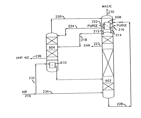
Referring to Figure 2, ultra high purity nitrogen column 604 operates at about the
same pressure as first column 602. Recall in the process of Figure 1 a nitrogen vapor
fraction was removed from a top section of first
CA20584~0
-- 8
column 602 and expanded with a portion of all being introduced to a middle portion of ultra
high purity nitrogen column 604. To achieve the recovery of ultra high purity nitrogen
product at a pressure almost equal to the inlet air supply pressure, the process of Figure 2
takes advantage of the incoming air stream as a means for effecting the desired boil-up in
ultra high purity nitrogen column 604. More particularly, the process comprises splitting an
air stream which has been freed of impurities and cooled to near its dew point, as
represented by line 210, into two fractions. One fraction is conveyed to boiler/condenser
610 in the bottom of ultra high purity nitrogen column 604 via line 232 with the balance of
the air stream supply being introduced to a lower section of first column 602 via line 234.
Some of the inlet air supplied via line 232 to boiler/condenser 610 is condensed and
introduced to an intermediate point to first column 602 as impure reflux.
As in the process of Figure 1, a nitrogen rich vapor fraction containing residual
volatile impurities is generated near the top of first column 602. A nitrogen vapor fraction
is removed from the upper most part of first column 602 via line 212 with a portion being
condensed in boiler/condenser 608. Similarly to the process in Figure 1, a portion of
nitrogen rich vapor concentrated in residual volatile impurities is removed from the top of
first column 602 via line 218 and charged to an intermediate section of ultra high purity
nitrogen column 604. The balance of the nitrogen rich fraction containing volatile
impurities is condensed in boiler/condenser 608 with the condensed fraction being returned
via line 214 to an upper most portion of first column 602 as reflux. The uncondensed
fraction concentrated in impurities is removed as a purge via line 216. Alternatively, stream
212 can be totally condensed in boiler/condenser 610 and no purge taken via line 216.
Impurities then would be removed from the ultra high purity nitrogen column. An overhead
is removed from ultra high purity nitrogen column 604 via line 220 and partially condensed
in boiler/condenser 608. The condensed portion is returned as reflux to an upper most
portion of ultra high purity nitrogen column 604 via line 224. This point is above the feed
introduction feed point of the nitrogen vapor fraction containing residual impurities from
first column 602. The uncondensed nitrogen fraction is removed via line 222 as a purge
stream and is not
CA20584~0
g
returned to the distillation system. Because of the high concentration of volatile impurities
in the purge stream, only a small amount of nitrogen need be vented as purge. Ultra high
purity nitrogen product is removed from the integrated distillation system as vapor fraction
via line 226. Gaseous nitrogen of lesser purity is obtained from nitrogen column 602 via
line 227.
A variation in Figure 2 would allow all of the nitrogen vapor fraction to be routed via
line 218 to ultra high purity nitrogen column 604 and thus the flow rate in line 212 would
be nearly zero. In this variation, there would be only one nitrogen stream condensing in
boiler/condenser 608. However the condensed portion (steam 224) would be split with one
portion returned as reflux to the ultra high purity nitrogen column 604, as shown in this
Figure 2, while another portion would be returned as reflux to first column 602.Figure 3 represents a variation of the process of Figure 2 producing large quantities
of ultra high purity nitrogen. The process utilizes four columns to accomplish the
separation, i.e., a first column 602, an ultra high purity nitrogen column 604, a third
column 606 and a fourth column 607. An air supply is introduced to the system via line
310, split into fractions 332 and 334 wherein fraction 332 is charged to boiler/condenser
610 to provide boilup. The resulting condensed air stream is then returned to first column
602 at an intermediate point for separation. A high pressure nitrogen rich vapor fraction
containing volatile contaminants is removed via line 318 and charged to the bottom of third
column 606 wherein some of the volatile components are stripped from the descending
liquid. A nitrogen rich vapor fraction containing a high concentration of volatile impurities is
removed via line 320, partially condensed in boiler/condenser 310. At least a portion of the
uncondensed nitrogen fraction rich in volatile impurities is removed as a purge via line 322
without return to the column. The balance of stream 320 is removed via line 324 and this
condensed fraction is returned as reflux to third column 606.
As in the embodiments of Figures 1 and 2, crude liquid oxygen is removed from the
first column 602 via line 328 and expanded. A portion of the subcooled liquid is partially
vaporized in boiler/condenser 310. In
CA2058490
-- 10 --
this embodiment, distillation trays have been added above boiler/condenser 310 to form the
fourth column. Crude liquid oxygen is fed at the top of the thus formed fourth column 607
and the ascending vapor strips the descending crude liquid oxygen of any dissolved
impurities. The vapor stream 339 is purged. The oxygen containing vapor fraction from
boiler/condenser 310 is removed via line 340 and the liquid in the sump is removed via line
346. These fractions are combined and introduced to ultra high purity nitrogen column 604
at an intermediate point. Liquid oxygen from the bottom of column 604 is removed,
expanded and. vaporized against a nitrogen vapor fraction in boiler/condenser 347. The
nitrogen fraction is removed from the top of ultra high purity nitrogen column 606 via line
350. The uncondensed nitrogen fraction rich in volatile components is removed a purge via
line 352 and the condensed fraction returned to ultra high purity nitrogen via line 353.
The liquid from the bottom of third column 606 is removed via line 354 and splitinto two portions. One portion is returned to first column 602 via line 356 as reflux and
the second portion isenthalpically expanded and introduced to the ultra high purity nitrogen
column 604 via line 358. In this manner, nitrogen vapor containing volatile impurities is, in
the final analysis, introduced to ultra high purity nitrogen column 604 as a feed. It simply
has undergone an initial separation in third column 606 prior to introduction to ultra high
purity nitrogen column 604. An ultra high purity gaseous nitrogen product is removed via
line 360 from ultra purity nitrogen column 604 at a location below the feed point
2 0 represented by stream 358. Refrigeration for boiler/condenser 347 located at the top of
ultra high purity nitrogen column 604 is effected by removing liquid oxygen from the
bottom of ultra high purity nitrogen column 604 via line 362 and isenthalpically expanding
and vaporizing that stream against the overhead from ultra high purity nitrogen column
604. The vaporized oxygen then is discharged via line 330 as a waste product.
Figure 4 describes a variation of the process of Figure 3. The process results in
lesser quantities of ultra high purity nitrogen being produced but there is an accompanying
coproduction of oxygen. The process generally involves the retaining of third column 606
as a conventional column with oxygen of high purity being withdrawn from the bottom of
the column and a
CA2~84 90
11 --
nitrogen product of standard purity, e.g., less than 5 ppm of oxygen being withdrawn as an
overhead from that column. More particularly air is introduced to first column 602 via line
410 wherein a nitrogen rich fraction containing impurities is generated. A portion of that
fraction is removed from the first column 602 via line 412 and condensed. In addition,
some of the nitrogen fraction rich in volatile impurities is removed from the section via line
418 to effect boiling in ultra high purity nitrogen column 604 and provide feed. A portion is
removed via line 419, expanded, and charged to an intermediate point in ultra high purity
nitrogen column 604 as feed. The balance is conveyed via line 421 and condensed in the
bottom of ultra high purity nitrogen column 604 in boiler/condenser 212. The condensed
nitrogen fraction in line 454 is combined with a liquid nitrogen stream 456 withdrawn from
the first column 602 and the combined stream 458 is isenthalpically expanded and charged
as reflux to the top of third column 606. As with the process in Figure 3, a nitrogen
fraction rich in volatile impurities is removed from an upper portion of ultra high purity
nitrogen column 604 via line 420 and partially condensed. The uncondensed portion is
removed as a purge via line 422 and the condensed portion is returned as reflux to column
via line 424. Crude liquid oxygen from the bottom of first column 602 is removed via line
428 and a portion is used to drive boiler/condenser 610 in the top of ultra high purity
nitrogen column 604. Any liquid and vaporized oxygen is removed via lines 431 and 440,
combined, and charged to an intermediate point in third column 606 wherein it is distilled.
Higher purity oxygen (higher than crude) is recovered from the bottom of third column 606
as a vapor via line 466. The balance of oxygen from line.428 is charged to an intermediate
point of column 606. A waste stream, as with many conventional nitrogen columns, is
taken from an upper portion of third column 606 via line 468 and nitrogen of standard
purity is removed as an overhead product via line 470. The ultra high purity nitrogen
product is removed as stream 426 from the bottom of ultra high purity nitrogen column
604.
Figure 5 is a variation of the process described in Figure 1 in that it involves the
generation of ultra high purity nitrogen at two pressure levels. The Figure 5 process also
involves coproduction of oxygen and ultra high purity nitrogen. More particularly air is
introduced to first column
CA20584~0
-- 12 --
602 via line 510 wherein a nitrogen rich fraction is generated and removed from the first
column 602 via line 512 and condensed in boiler/condenser 608. A portion of nitrogen rich
vapor fraction is removed via line 518 wherein a portion is removed via line 519, expanded
and charged to an intermediate point in ultra high purity nitrogen column 604. The balance
is removed via line 521 and condensed in boiler/condenser 610 located in the bottom of
third column 606. That portion of the condensed nitrogen fraction is returned as reflux to
first column 602. As with the process in Figure 4, a nitrogen fraction rich in volatile
components is removed from an upper portion of ultra high purity nitrogen column 604 via
line 520 and partially condensed. The uncondensed portion is removed as a purge via line
522 and the condensed portion is returned to column 604 via line 524. As with the
embodiments in Figures 1 and 2, crude liquid oxygen is removed from first column 602 via
line 528. Its pressure is decreased across a valve to the pressure of third column 606 and
then it is fed to phase separator 572. The liquid is separated from the vapor in phase
separator 572 with the liquid being introduced to the third column 606 via line 558. The
flashed vapor 524 from separator 572 is mixed with the waste stream. An ultra high purity
gaseous nitrogen product is removed via line 570 from third column 606. A higher purity
oxygen stream is removed via line 568 from the bottom of third column 606.
Further embodiments of Figures 1-5 are envisioned. For example, Figure 1 shows
modifications to a single distillation column nitrogen generator producing nitrogen at
pressures greater than 60 psia. In this embodiment, ultra high purity nitrogen is shown as
gaseous product but if needed, liquid nitrogen of ultra high purity can also be withdrawn
from the bottom of this ultra high purity nitrogen column. The use of additional separation
stages (trays or packing~ above the withdrawal point of the contaminated nitrogen vapor
from the first column is optional. One may eliminate purging of volatile contaminants from
the boiler/condenser located at the top of this column. However, if a purge is not taken,
then the amount of distillation duty needed to remove light contaminants from the nitrogen
in the ultra high purity nitrogen column will increase.
Another optional modification of Figure 1 would show the withdrawal of a portionof the contaminated nitrogen vapor stream from the first column,
CA20584qO
-- 13 --
condensation in the boiler/condenser located at the top of the ultra high purity nitrogen
column and the returning of liquid to the first column as a liquid reflux stream. By
condensing a portion of the contaminated vapor stream from the first column in the
boiler/condenser located at the top of the ultra high purity nitrogen column and returning
the condensed liquid as reflux to the first column, one can reduce the vapor flow in the
ultra high purity nitrogen column and also the heat duty need in the boiler/condenser
located at the bottom of this column. As a result, the diameter of the ultra high purity
nil,ogen column and the size of the bottom boiler/condenser may be decreased making the
process even more attractive. One reason that it is possible to split, i.e., withdraw a
portion of the contaminated nitrogen vapor steam from the first column, is that the vapor
flow needed at the bottom of ultra high purity nitrogen column to step the descending liquid
of the light impurities is relatively small; i.e., the L/V in the bottom section of the ultra high
purity nitrogen column is much higher than 1 (usually higher than 5). This decreases the
need for the boilup in the bottom of the ultra high purity nitrogen column and allows the
condensation of some nitrogen vapor from the first column directly in the boiler/condenser
located at the top of the ultra high purity nitrogen column.
Figure 2 shows an embodiment where the ultra high purity nitrogen column
operates at a pressure similar to the pressure in the first column. In the process of Figure
2, two types of gaseous nitrogen products are produced. A large fraction of gaseous
2 O nitrogen is produced at a purity typical of standard cryogenic processes (standard purity
nitrogen, e.g., less than 5 ppm oxygen) while the rest is produced as ultra high purity
nitrogen. By adding trays at the top of the first column and above the regular nitrogen
product withdrawal point, one can reduce the concentration of impurities heavier than
nitrogen (such as oxygen, argon and carbon monoxide) to the ultra high purity nitrogen
column. As a result of the pressure of the columns being the same, the bottom of the ultra
high purity nitrogen column can no longer be boiled by the nitrogen stream obtained from
near the top of the first column. Thus, the required boilup is provided by condensing a
portion of the feed air stream in the boiler/condenser located
CA20584~0
-- 14 --
at the bottom of the ultra high purity nitrogen column. Alternatively, either all or a portion
of this heat duty could be provided by heat exchange against the O2-rich (crude liquid
oxygen) liquid from the bottom of the first column. The ultra high purity nitrogen product is
withdrawn from the bottom of the ultra high purity nitrogen column.
It is worth mentioning that in cases where heat duty at the bottom of the ultra high
purity nitrogen column is provided by condensing a nitrogen stream, it is possible to keep
the pressure of the ultra high purity nitrogen and the first column the same. In such cases,
a gaseous nitrogen stream obtained from the first distillation column could be warmed,
boosted in pressure, recycled, cooled and then condensed in the boiler/condenser located at
the bottom of the ultra high purity nitrogen column.
In Figure 3, use of trays in the fourth column can be optional. If trays are not used,
all of the vapor from the boiler/condenser located at the top of the third column 606 is fed
to the ultra high purity column. A gaseous purge would not be taken via line 339.
Figure 5 describes an embodiment where both oxygen and ultra high purity nitrogen
products are produced. Once again the relationship between the ultra high purity nitrogen
column and the first column is very similar to the one shown in Figure 1 except that
nitrogen vapor from the top of the ultra high purity nitrogen column is condensed against a
higher purity oxygen now at the bottom of the third column and not against crude liquid
oxygen. Furthermore, in Figure 5 crude liquid oxygen from the first column is flashed in a
2 0 separator and the liquid from this separator is fed to the third column. The vapor is mixed
with the waste stream from the third column. The liquid nitrogen reflux to the third column
comes from the bottom of the ultra high purity nitrogen column and not from the first
column. These two steps keep the concentration of the lights in the third columnextremely low and, therefore, gaseous nitrogen from the top of the third column is of ultra
2 5 high purity. Optionally, a column containing packing, trays, etc. can be substituted for
separator 572 to concentrate volatile impurities in the vapor phase and minimize the
concentration of volatile impurities in the liquid feed stream 558.
CA20584~0
In summary, the current invention recognizes that when a cooled air feed is distilled
in a first column, the nitrogen vapor near the top of the column which is concentrated in
light conldr"inants can be judiciously distilled in a ultra high purity nitrogen column to
provide a nitrogen steam which is exceptionally lean in the light contaminants. This is
achieved by the judicious integralion of the reflux and boilup needs of the ultra high purity
nitrogen column with the first column in the cryogenic air separation process. More
particularly, the separation stages in the ultra high purity nitrogen column above the feed
point of contaminated nitrogen vapor steam concentrate the lights in the nitrogen vapor.
When the top section of the ultra high purity nitrogen column operates at reflux ratios close
to unity, the vapor from the top is nearly totally condensed. The uncondensed portion of
the vapor has a very high concentration of the lights, i.e., typically more than 1000 fold
over that in the feed air, and purging of the stream permits the removal of lights from the
system. Because the concentration of lights in the purge stream is large, the flow rate of
the purge stream is fairly small and nitrogen recovery based on feed to the system remains
high.
The condensation duty in the boiler/condenser located at the top of the ultra high
purity nitrogen column is provided by boiling a suitable process liquid. Typically, this liquid
is the crude liquid oxygen from the bottom of the first column, but at a pressure lower than
that of the first column. Alternatively, a liquid derived from the crude liquid can also be
boiled in this boiler/condenser. The key point is to choose a liquid such that its boilup in
this boiler/condenser does not have a detrimental effect on the process.
The liquid nitrogen in the ultra high purity nitrogen column at a location near the
contaminated gaseous feed has a very low concentration of the lights. This is due to very
high relative volatilities of the three largest light contaminants, e.g., H2, He and Ne with
respect to the nitrogen. As a result, any liquid descending to the bottom section of the
ultra high purity nitrogen column has very low concentrations of lights and is easily stripped
of these conla", -a"l~ by the ascending vapor. To maintain appropriate stripping the ratio
of liquid to vapor flowrate in the
2058490
- 16 -
stripping section of the ultra high purity nitrogen column should be greater
than one (typically greater than five). The boilup at the bottom of this
column is provided by a suitable process stream. When a stream other than a
nitrogen stream from the top of the first column is used, one has the
opportunity to produce ultra high purity nitrogen at the same pressure as in
the first column.
113RLB