Note: Descriptions are shown in the official language in which they were submitted.
71576-44
2058594
Background of the Invention
This invention relates to an electronic switch in a
telephone system and, in particular, to an electronic switch
which provides call routing and connection to service node/-
intelligent peripherals.
Electronic switches are in use today which enable
subscribers to be routed to so-called "service node/intelligent
peripherals" (referred to hereinafter as "SN/IPs" or "IPs").
Typically, a SN/IP is a facility in the telephone system which
can be called by a subscriber for some specified service.
These facilities are usually provided with some degree of
intelligence so that the subscriber and SN/IP can communicate
in an interactive fashion. Examples of SN/IPs in use today are
the voice mail service nodes now being offered by telephone
companies to subscribers for voice mail services.
In present telephone systems which employ SN/IPS, for
a subscriber to gain access to a SN/IP, the subscriber must
first dial an access code or number. This dialed access code is
then analyzed like a normal call by the call routing digit
receiver and analyzer functionality of the switch. Once the
digits are analyzed and the SN/IP identified, the call is routed
by the switch to the SN/IP over an appropriate communication
path. After connection to the SN/IP, to place another call the
subscriber must first hang up, i.e., go on-hook, to cause the
$~
f
2058594
-
switch to terminate the communication path with the SN/IP.
Also, when connected to a SN/IP, all existing systems
require that any digit transmission be dual tone multiple
frequency (DTMF) transmission.
The latter requirement prevents subscribers with dial
pulse transmissions, i.e., rotary dialing equipment, from being
able to use the SN/IP facilities. Also, the need to initially
dial an access code to reach a SN/IP and to have to terminate or
hang-up in order to be able to dial a further call when
connected to a SN/IP present drawbacks with respect to time,
effort and demands placed on the subscriber.
It is, therefore, an object of the present invention to
provide an electronic switch and SN/IP in a telephone system
which have been improved to avoid the aforesaid drawbacks.
It is a further object of the present to provide the
aforesaid improved switch and SN/IP, while preserving other
normal and usual electronic switch functions.
Summary of the Invention
i
In accordance with a first aspect of the present
invention, the above and other objectives are in part realized
i in an electronic switch which is adapted to provide routing and
connection of a subscriber to a SN/IP in response to an off-hook
status for the subscriber. The electonic switch is further
i - 2
2058~94
adapted to be able to receive and analyze dialed digits from the
off-hook subscriber for further call routing and connection both
when the aforesaid connection to the SN/IP is being established
and during its maintenance. To this end, the switch is
additionally adapted, upon receipt of dialed digits from the
subscriber, to terminate the connection process with respect to
the SN/IP and to process the received digits via its digit
analyzer functionality in the normal manner.
With the electronic switch of the invention so adapted,
a subscriber going off-hook is automatically connected with an
associated SN/IP and the subscriber can interact with the SN/IP
immediately and without any need to dial. ~urthermore, since
dialed digits from the subscriber can still be received and
processed by the digit analyzer functionality of the switch and
since connection to the SN/IP is dropped upon dialed digits
being received, the subscriber is free to make a call at any
time without having to hang-up.
In the embodiment of the invention to be disclosed
hereinafter, the electronic switch includes an off-hook status
functionality for detecting off-hook status of a subscriber, a
routing digit receiver and analyzer functionality for receiving
and analyzing dialed digits, a routing and connection
functionality for routing and connecting calls and a control
functionality for effecting overall control of the other
functionalities.
2058594
In a further aspect of the invention, the electronic
switch of the invention is additionally adapted to provide
.- call routing and connection of a subscriber to a SN/IP through
conventional access code dialing and conventional routing, but
with the added functionality of dial pulse to DTMF conversion
for digits transmitted over the established communication
path. In this way, coded access to a SN/IP over a stable
communlcatlon path (l.e., one established by dlaled digits~
can be effected for subscribers with dial pulse dialing.
In yet a further aspect of the present inventionr
the SN/IP is adapted to perform dialing functions and to
invoke call features (transfer,etc.) for a subscriber
connected to the SN/IP (either through off-hook status or
access code dialing) upon the request of the subscriber and
the electronic switch functionality is further adapted to
process these dialing functions and call features as if made
by the subscriber, including billing of requested calls to the
associated subscriber.
In accordance with the present invention, there is
provided a central office electronic switch for use ln routing
calls to and from a number of telephone subscribers and for
use with a service node/intelligent perlpheral (SN/IP) able to
be connected wlth said central office electronic switch
comprlsing:
means for receiving and analyzing digits;
means for routing and connecting calls; and
control means for upon a telephone subscriber going
off-hook: controlllng sald dlglts recelving and analyzing
-- 4
71576-44
2~ 3 ~
rneans to be able to receive and analyze digits transmitted
from sald off-hook telephone subscrlber and controlling said
routing and connecting rneans to autornatically establish a
first communication path between sald off-hook telephone
subscriber and said SN/IP.
In accordance with another aspect of the invention,
there is provided a telephone system comprising:
a number of teiephone subscribers;
a service node~intelligent peripheral lSN/IP); and
a central office electronic switch for routing calls
to and from said telephone subscribers and able to be
connected to said SN~IP, said central office electronic switch
comprlslng means for receivlng and analyzing digits; means
for routing and connecting calls; and control means for upon a
telephone subscriber going off-hook: controlling said digits
receiving and analyzing means to be able to recelve and
analyze dlglts transmltted from said off-hook telephone
subscriber and controlling said routing and connecting rneans
to automatically establish a flrst communication path between
0 sald off-hook telephone subscriber and said SN/IP.
In accordance with a further aspect of the
invention, there is provided a rnethod for use in routing calls
to and from a number of telephone subscribers and for use wlth
a service node~intelligent peripheral (SN/IP) comprising:
at a central office electronic switch;
receiving and analyzing digits;
routing and connecting calls; and
controlling said steps of receiving and analyzing
-- 5
-~ 71576-44
~ g~ 9 ~
digits and routing and connecting calls including: when a
telephone subscriber goes off-hook allowing diglts from said
off-hook telephone subscriber to be able to be received and
analyzed; and automatlcally establishing a first communication
path between said off-hook telephone subscriber and said
SN/IP.
- 5a -
'~'
ir.t.
71576-44
71576-44
205~594
In accordance with a still further aspect of the
invention, there is provided a service node/intellige~ peripheral
(SN/IP) for use with a central office electronic switch for
routing calls to and from a number of telephone subscribers,
said central office electronic switch being able to communicate
with said SN/IP and comprising: means for receiving and
analyzing digits; means for routing and connecting calls; and
control means for upon a telephone subscriber going off-hook:
controlling said digits receiving and analyzing means to be
able to receive and analyze digits from said off-hook telephone
subscriber and controlling said routing and connecting means to
automatically establish and/or maintain a communication path
between said off-hook telephone subscriber and said SN/IP; said
SN/IP comprising: means for receiving a verbal request from an
off-hook telephone subscriber on a communication path
automatically established and maintained between said SN/IP and
said central office electronic switch as a result of said off-
hook telephone subscriber going off-hook, said request being a
request that the SN/IP call a number and/or invoke a calling
feature; and means for responding to said verbal request by
providing signaling for coupling over said communication path to
said central office electronic switch, said signaling being such
that said control means of said central office electronic switch
responds to said signaling by controlling said routing and
connecting means and said digits receiving and analyzing means
to process said call to said number and/or invoke said call
feature as if called and/or invoked, respectively by said off-
hook telephone subscriber.
;: - 6 -
20585~4 71576-44
Brief Description of the Drawings
The above and other features and aspects of the present
invention will become more apparent upon reading the following
detailed description in conjunction with the following drawings
in which:
FIG. 1 shows a telephone system utilizing an electronic
switch and SN/IP in accordance with the principles of the
present invention;
FIG. 2 shows the telephone system of FIG. 1 with the
electronic switch and SN/IP o,perating in implicit mode;
FIG. 3 shows the telephone system of FIG. 1 with the
electronic switch and SN/IP operating in explicit mode;
FIG. 4 illustrates in simplified form various states
of the subscriber, electronic switch and SN/IP of the system of
FIG. 1 where a call is made without assistance by the SN/IP;
FIGS. 5 and 6 illustrate in simplified form various
states of the subscriber, electronic switch and SN/IP for the
system configurations of FIGS. 2 and 3 and where a call is made
with interaction of the SN/IP; and
FIG. 7 is a more comprehensive chart showing the states
of the subscriber, electronic switch and SN/IP for various
operating conditions of the system of FIGS. 1 - 3.
Detailed Description
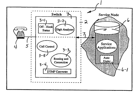
FIG. 1 shows a telephone system 1 in accordance with
the principles of the present invention. The system 1 comprises
a central office 2 which includes an electronic switch 3. The
switch 3 controls routing and connection, i.e., communication,
71576-44
205 85 94
of telephone calls to and from telephone subscribers 4 served by
the central office and connected thereto over links 5. The
switch also controls routing and connection of calls to a service
node/intelligent peripheral device (SN/IP) 6 over a further link
7.
The SN/IP, in the present example, is shown as an
interactive system which provides subscribers connected thereto
with prompts and responses and which responds to requests from
the subscribers. A typical type of system might be a voice
interactive system such as, for example, a voice mail system.
Also in the present example, SN/IP 6 communicates with
the switch 3 via DTMF signaling which is usual for these types
of devices. The subscribers 4, on the other hand, may
communicate with the switch 3 using either dial pulse signaling
or DTMF signaling and may utilize analog or digital telephone
stations.
The switch 3, as shown, is a program driven digital
switch having standard routing and connectivity functions.
Typical functions might be those available in so-called "class
5" digital telephone switches such as, for example, AT~T's No. *5
ESS or Northern Telecom's DMS-100. Functions or features
available via such switches might be for example, call waiting,
call transfer, call forwarding and directed call pickup.
Certain of the basic functions carried out by the
switch have been represented pictorially in the figure. As can
be seen, the switch includes an off-hook status functionality 3-1
Trade-mark
- 7a -
71576-44
20585 94
for detecting the off-hook status of the subscribers 4 and SN/IP
served by the switch. The switch also contains a call routing
digit receiver and analyzer functionality 3-2 which receives and
analyzes incoming digits to determine call routing actions based
on the digits.
A call routing and connection functionality 3-3
effects call routing and connection based upon the determinations
made by the digit analyzer functionality. A further conversion
functionality for converting dial pulse digits received at the
switch to DTMF digits for transmission from the switch is also
provided. These functionalities as well as all other
functionalities of the switch are controlled by a control
functionality 3-5.
In accordance with a first aspect of the present
invention, the functionality of switch 3 is further adapted so
as to enable automatic routing and connection of a subscriber 4
to the SN/IP 6 when the subscriber is in an off-hook status
i.e., when the subscriber initially goes off-hook or is returned
to an off-hook status duringcallprocessing. Furthermore, this
adaptation is such that during the automatic routing and when
connected to the SN/IP 6, as a result of this routing, the switch 3
is still able to receive and respond to dialed digits from the
subscriber. In particular, the switch 3 is configured such that
upon receipt of such dialed digits, the switch 3 ceases the
A - 7b -
_'--
205859~
.
routing and connection processing of the subscriber to the SN/IP
and then proceeds with connection and routing based upon the
dialed digits. In effecting such cessation, the switch 3 may
cease the routing during the routing process itself, or it may
allow the routing and connection to be effected and then drop
the connection, or if connection has occurred, the switch will
drop the connection.
With the switch configured in this manner, the switch
exhibits a mode of operation, i.e., referred to as the "implicit
mode", which allows a subscriber in off-hook status immediate
access to the SN/IP 6 without the need to dial. Furthermore, in
this implicit mode of the switch, a subscriber's dialed digits
will be accepted by the switch so that the subscriber can place
a call without having to hang-up.
This action of the switch 3 is schematically shown in
FIG. 2 by the connecting path 3-6 between the digit analyzer
functionality 3-2 of the switch 3 and the subscriber 4 and the
simultaneous connecting path 3-7 to the SN/IP through the
routing functionality 3-3. Depending upon the character of the
SN/IP 6, the connection to the subscriber 4 may be responded to
by an announcement or tone or the SN/IP 6 may simply wait for
prompts from the telephone station to initiate an interactive
session. The SN/IP 6 may also immediately provide messages to
the subscriber 4 if this operation is desired.
In effecting automatic connection of the off-hook
.
- 20S859~
subscriber 4 to the SN/IP 6 as above-described, the switch 3 is
adapted to provide dial tone to the subscriber in usual
fashion. Also, the routing and connection functionality 3-3 in
setting up the connection to the SN/IP 6 transmits the
subscriber's identification number and service code which can be
used by the SN/IP for identification, tracking and other
purposes as desired. When the functionality 3-3 completes the
connection and the communication path 3-7 is established, dial
tone to the subscriber 4-1 is dropped and the subscriber has
immediate voice path access to the SN/IP 6.
' As above-indicated, once the communication path 3-7 is
in place, the subscriber 4 can interact with the SN/IP 6 in
usual fashion. When the subscriber completes this activity, if
the subscriber hangs-up, the switch 3, via its described
functionality, detects the change in off-hook status i.e.,
recognizes the on-hook condition) and, as a result, drops the
connection to the SN/IP and releases its other functionalities
from the subscriber. Alternatively, if the subscriber dials a
number this dialing, as above-described, will cause the switch 3
to drop the connection to the SN/IP. The switch then proceeds
to normally process the dialed call via the digit analyzer and
routing functionalities.
When connected to the SN/IP 6 in this implicit mode
the switch 3 is also adapted to treat the off-hook subscriber as
busy. Call waiting tone will thus not be received during this
, ' _ g
71576-44
2058594
mode of operation and will be responded to by the switch with a
busy signal. Furthermore, a hook flash from the subscriber 4
will cause the switch 3 to drop the connection to the SN/IP 6
during the brief on-hook signal condition of the hook flash.
At the end of the hook flash and return of the signal condition
to off-hook, the switch 3 again detects off-hook status for the
subscriber 4, and the connection to the SN/IP 6 will be
reestablished as above-described.
In accordance with a further aspect of the invention,
the switch 3 is additionally adapted to enable access to the
SN/IP 6 over a stable communication path which can be affected
in standard fashion via access code dialing. In this so-called
"explicit mode" of operation, an off-hook subscriber 4 dials an
access code which is understood by digit analyzer functionality
3-3 of the switch to require routing and connection to the SN/IP
6. This dialing is processed in normal fashion by the routing
functionality to establish a stable communication path to the
subscriber.
Since the subscriber must dial digits to invoke the
explicit mode, the automatic connection to the SN/IP 6
established when the subscriber goes off-hook is dropped when
explicit mode is initiated. A1SO~ since explicit mode is
effected by normal processing, the subscriber 4 no longer has
access to the digit analyzer, routing and other functionalities
of the switch 3. As a result, in order to dial a further
number, the subscriber must perform some additional action other
~, - 10 -
2058~i9
r
than merely dialing digits, as in implicit mode.
The subscriber's lack of access to the switch
! functionalities prevents digits being transmitted by the
...
subscriber in explicit mode from being applied to the
conversion functionality 3-4. As a result, a subscriber 4
operating on dial pulse signaling, cannot effectively
communicate with the SN/IP 6 in explicit mode.
In accordance with this aspect of the invention, the
switch 3 is further adapted to overcome this shortcoming by
allowing access of the subscriber in explicit mode to the
conversion functionality 3-4 of the switch. As a result,
subscribers with dial pulse signaling will have this signaling
converted to DTMF signaling which can now be accepted by the
SN/IP 6.
The above aspect of the invention is illustrated in
FIG. 3 which illustrates a subscriber 4 operating in explicit
mode. As can be seen, a stable communication path 3-8 is
i established between the subscriber 4 and SN/IP 6 through the
~I routing functionality 3-3. This path has access to the
conversion functionality 3-4, but not the digit analyzer
functionality 3-3, as above-described.
In the explicit mode of operation, a subscriber 4
(either dial pulse or DTMF) can now interact with the SN/IP 6 in
,
-- 11 --
-
~ 2058594 71576-44
usual fashion over the stable communication path 3-8. Once the
subscriber 4 goes on-hook, the communication path to the SN/IP 6
is disconnected by the switch in usual fashion. Also, in
explicit mode, any hook flash or similar signaling function is
passed to the SN/IP 6 and processed by the switch in usual
fashion. Thus, for example, a hook flash response to a call
waiting tone will enable the subscriber to access the call
waiting feature, while the stable connecting path 3-8 to the
SN/IP 6 is placed on hold in accordance with normal call waiting
processing.
In accordance with yet a further aspect of the present
invention, the switch 3 and the SN/IP 6 are additionally adapted
such that, at the request of a subscriber, the SN/IP is able to
provide signaling to the switch 3 over a communication path
between the subscriber and SN/IP established by the switch in
implicit or explicit mode. The ability to provide this signaling
permits the SN/IP 6 to perform dialing for the subscriber as well
as to invoke other call features or functions in the subscriber's
assigned dialing plan. The switch 3, in turn, is adapted to
respond to this signaling by processing the dialing or invoked
functions as if placed by the subscriber 4, including allocating
any billing to the subscriber. The above is illustrated in
FIGS. 1-3 which show the SN/IP 6 as configured to have a signal
generator and auto dialer 6-1 for signaling the switch 3 and
dialing numbers based on requests from subscribers 4 connected
to the SN/IP.
- 12 -
71576-44
2058594
More particularly, upon receipt of dial commands from
a subscriber 4, the SN/IP 6 via its dialer 6-1 provides a
preselected signal to the switch 3. This signal when received
at the switch causes the switch functionalities to place the
subscriber 4 on hold and to give the SN/IP 6 access to the digit
analyzer functionality 3-2. The SN/IP 6 then dials the digits
of the number to be called and upon receipt of the digits by the
switch 3, the switch functionalities drop the connection to
SN/IP 6 and process the dialed digits in normal fashion. The
switch 3, however, interprets the call as if it were placed by
the subscriber 4 and, thus, billing records and other attributes
of the call normally developed by the switch 3 are associated
with the subscriber.
FIGS. 5 and 6, illustrate the states of the subscriber
4, the switch 3 and SN/IP 6 for the aforesaid auto-dial
operation effected in implicit and explicit modes, respectively.
FIG. 4, in turn, illustrates these states for direct dialing by
the subscriber 4 in implicit mode.
Referring to FIG. 4, in response to a subscriber 4
going off-hook (state U(O)), the switch 3 (state N(l)) seizes
a trunk in the link 7 to the SN/IP 6 and transmits the service
code and identification number (USR_ID) of the subscriber to
the SN/IP (state IP(l)). The switch 3 (state N(l)) also makes
available to the subscriber the digit analyzer functionality
3-3 as well as sends the subscriber dial tone (state U(1)).
- 13 -
`:
71576-44
20585~4
Upon the SN/IP 6 transmitting answer/supervision to
the switch 3, the switch 3 removes dial tone from the subscriber.
When the subscriber then dials (state U(2)), the switch 3, upon
receipt of the digits, drops the connection to the SN/IP 6,
causing the latter to return to on-hook status (state IP(O)).
The switch 3 then continues to receive the digits and at the
end of the digit transfer, (state N(4)), processes the dialed
digits, resulting in an active call status (states N(6) and
U(5)) for the switch 3 and subscriber 4.
If instead of the subscriber 4 dialing the number to
be called, the subscriber requests the SN/IP 6 to perform the
dialing, the states of the subscriber, switch and SN/IP in
implicit mode are similar to those shown in FIG. 4 to the point
of removal of dial tone to the subscriber. At this point, as
shown in FIG. 5, the SN/IP 6 signals (shown as an inverted wink)
the switch 3 that it is dialing for the off-hook subscriber.
Upon receipt of this signal, the switch 3 places the
subscriber on hold (state U(3)) and disables the subscriber
from access to the digit analyzer functionality (state N(2)).
The switch 3 also at this time grants access to the digit
analyzer functionality to the SN/IP 6. The switch 3 then signals
(shown as a wink) the SN/IP (state IP(3)) which responds by
transmitting (state IP(3)) the dialed digits. Upon receipt of
all the digits (states N(3) and N(4)), the switch drops the
connection to SN/IP
- 14 -
20~859 1
6 causing it to return to on hook status (state IP(o)). The
'I switch then completes processing of the call as if made by the
subscriber 4 (states N(6) and U(5)).
In the event the subscriber wishes the SN/IP to dial in
explicit mode, again the initial states of the switch,
subscriber and SN/IP to the point of removal of dial tone to the
subscriber are as shown in FIG. 4. The subsequent states are
shown in FIG. 6 and are initiated by the subscriber dialing the
appropriate access code digits for the SN/IP 6. The switch 3,
initially in implicit mode, upon receipt of these digits, first
drops the connection to the SN/IP (states N(2&3)), placing the
SN/IP on-hook (State IP(o).
At the end of digit transfer from the subscriber, the
switch 3 (state N(4)) places the subscriber on hold, analyzes
the digits and responds thereto by reestablishing a connection
to the SN/IP (state N(5)) i.e., seizes link to SN/IP, transmits
service code and identification (state N(5)) and obtains
answer/supervision from SN/IP (state N(l)). The switch 3 also
acts at this time, if necessary, to convert dial pulse signaling
from the subscriber to DTMF signaling for the SN/IP.
If the SN/IP 6 is now instructed to dial a call by the
' subscriber 4, the procedure follows a similar procedure as that
described and shown in FIG. 6. More particularly, the SN/IP
; signals the switch 3 (shown as an inverted wink) which causes
the switch (state N(2)) to stop conversion, place the user on
- 15 -
` 20~8594
hold and grant access to the digit analyzer functionality to the
SN/IP. The switch also then signals the SN/IP (shown as a wink)
(state IP(3)).
The SN/IP thereupon transmits the digits (state IP(3))
and at the end of digit transfer (states N(3), N(4)), the switch
3 places the SN/IP on hook (state IP(O)). The switch 3 then
processes the call in normal fashion (states U(5) and N(6)), as
if placed by the subscriber.
FIG. 7 shows a more detailed version of the states of
the switch 3, subscriber (also referred to as user) and SN/IP
for the different operating modes discussed above. The
references and abbreviations used in FIG. 7 have the same
meanings as used herein and based upon the descriptions
hereinabove and hereinbelow the chart is believed to be self
explanatory and not in need of further detailed discussion.
It should be noted that in performing the functions
described above, the switch 3 and SN/IP 6 are configured so that
the normal constraints of the standard receiver off hook (ROH)
, timer (e.g., approximately 20 seconds) are satisfied during all
i~ call processing. Furthermore, to ensure that the conversion
,j from dial pulse to DTMF signaling can occur in satisfactory
; fashion, the holding times of any digit receivers used in the
switch 3 for this purpose must be adjusted to accommodate the
required holding times. The switch 3 configuration further
i! provides that all calls complete in usual fashion with respect
-- 16 --
~, .
.
20S8594
Ii to the terminating parties class of service (i.e, the
i terminating station group restrictions and terminating
features,e.g., call forwarding, ringing, etc.)
If should also be noted that the design of the switch 3
is such that if no answer/supervision is received from the SN/IP
6 during routing and connection to establish implicit mode, the
switch 3 does not effect connection and the subscriber continues
to receive dial tone. In such case, switch operation will
continue as normal POTS operation. In the case of the explicit
mode, however, since the subscriber has explicitly requested
connection to the SN/IP, if the SN/IP is busy, the usual
recorder tone will be received by the subscriber to indicate
that the request cannot be fulfilled.
Also, when in implicit mode of operation, a hook flash
by the subscriber will be understood by the switch 3 as
requiring that the switch disconnect from the SN/IP 6 and then
~' institute another reconnection procedure to the SN/IP. If a
i subscriber is connected to the another party or to the SN/IP in
; explicit mode (i.e., a stable talking path), then a hook flash
!' by the subscriber station is processed by the switch 3 in usual
fashion by placing the other party or SN/IP on hold and then the
switch 3 institutes a further connection to the SN/IP in
implicit mode.
The functioning of the SN/IP 6 to provide signaling for
the subscriber can also be utilized in explicit mode operation
- 17 -
20~591
...
to permit the subscriber to terminate explicit mode and return
i to implicit mode. Thus, upon the subscriber transmitting a
predetermined message indicating return to implicit mode, the
SN/IP 6 will signal the switch 3 with a message indicating the
connection to the SN/IP 6 in explicit mode should be dropped.
When this occurs, the switch 3 will return off-hook status to
the subscriber 4 and, as a result, institute reconnection to the
SN/IP in implicit mode.
The discussion of explicit mode operation and the
features of dial pulse to DTMF conversion and signaling by the
SN/IP were described above in a system 1 which also has implicit
mode operation. However, these features can be used in an
explicit mode operating system not having an implicit mode.
Also, the signaling feature of the SN/IP can be used in an
implicit mode system which does not have an explicit mode.
In all cases, it is understood that the
above-identified arrangements are merely illustrative of the
many possible specific embodiments which represent applications
of the present invention. Numerous and varied other
I arrangements can readily be devised in accordance with the
principles of the present invention without departing from the
spirit and scope of the invention.
~, ~
- 18 -
`, ,