Note: Descriptions are shown in the official language in which they were submitted.
2058606
ELECTRICAL CONNECTOR PANEL
FIELD OF THE INVENTION
This invention relates to electrical cable connectors
which fasten to the outer chassis of electrical equipment,
such as computer terminals. More specifically, it relates to
an electrical connector junction chassis panel having
permanently installed fastener means.
PRIOR ART AND BACKGROUND OF THE INVENTION
The electrical equipment in the computer industry
typically uses internally and externally-threaded loose
standoffs, spacer washers, lock washers and nuts to attach
the electrical receptacle to the chassis and then the plug to
the receptacle. Figure 1 shows a typical assembly of parts
found at the rear of the chassis for connecting incoming and
outgoing electrical data cables. The connectors are multiple
pin-and-socket receptacles and plugs which electrically
interconnect and attach the data transmission cables from the
computer chassis to related peripheral devices, such as
printers, plotters or other computers. These connectors have
a modified elongated "D" shape to ensure orientation in their
mounting holes and also orientation with the mating plugs.
They have become known as "D" connectors. Pin configuration
shell sizes, mounting holes, and the like have been
standardized throughout the world and all manufacturers meet
these standards.
Because it was never anticipated that the chassis panel
connectors would be used in the volume in which they are
manufactured today, no attempt in the past has been made at
using other than loose hardware to either attach the
receptacle to the chassis or to attach the plug to the
-1- ~.
205~606
receptacle. The standardized mounting hole diameter cutout
size, and center-to-center distance were established usir.g
loose hardware, typically a #40 screw and nut. Previous
attempts at eliminating the loose hardware to provide fewer
number of parts by using, for instance, permanently installed
self-clinching fasteners in the existing chassis mounting
holes met with failure due to the very rin; ~1 spacing
between the screw hole and the connector cutout in the panel.
To date, no attempt has been successful in installing a
standoff into the chassis due to this limited edge distance.
Furthermore, there exists a problem in the art with
accommodating different chassis panel thicknesses. It is
important that the mounting flanges of the mating receptacle
and plug be fastened the proper distance apart. If the
length of the mounting standoff is too great, the plug will
not be inserted deeply enough into the receptacle, thereby
jeopardizing a proper electrical connection. On the other
hand, if the length of the standoff is too short, the plug
will bottom out against the receptacle and the plug flange
may be bent or broken as the plug screw is tightened down to
the shoulder of the standoff. Because in the existing art
the standoff is located between the outside face of the panel
and the plug, a change in panel thickness will vary the
plug/receptacle spacing. In order to achieve the proper
standoff distance from the outside face of the panel, it is
the usual practice in the art to vary the standoff length by
adding or subtracting loose washers, such as those shown in
Figure 1.
SUMMARY OF THE lNV~:N'l'lON
The cbjects of the invention relate to reducing the
overall costs of the cable connector panel of the type
described above by both reducing the cost and number of the
2058606
components and bY creating a fastening system which reduces
the labour lntensity of lnstalling the components.
Additlonally, another obiect of the inventlon is to
deslgn a less expenslve electrlcal connector panel, which
lncludes permanently lnstalled, standoff fasteners.
The above-mentioned oblects are accompllshed ln
accordance with the invention which broadly resides in an
electrical panel, comprlslng: (a) a flat panel havlng first
and second opposing faces and fastener mountlng holes; and Ib)
a standoff cllnch-type fastener installed into the flrst face
of sald panel and pressed lnto one of said fastener mounting
holes so that a standoff portlon of sald fastener extends
beyond sald second face of sald panel and no portlon of said
fastener abuts sald second face of sald panel.
More speclflcally, the appllcants have devlsed an
electrlcal equlpment chassls havlng a cable connector panel
with inside and outside opposing faces, comprising
(a) a panel affixed to said chassls having a
receptacle cutout and fastener mounting holes;
(b) a standoff clinch-type fastener installed into
the inside face of said panel, said fastener including a
standoff
-~? '-3
r~ ~ 7 1 5 9 3 ~ 1 0
2058606
portion extending beyond the outside face of said panel and
without any portion which abuts the outside face of said
panel;
(c) a pin-type electrical receptacle mounted by said
fastener to the inside face of said panel and extending
through said cutout;
(d) a standoff shoulder located at the end of said
standoff portion of said fastener; and
(e) an electrical plug mated with said receptacle and
releaseably affixed to and abutting said standoff shoulder of
said fastener.
The invention achieves the following advantages. The
fastener utilizes clinch installation and, hence, there are
no loose parts to fall into the interior of the chassis and
cause malfunctions. The fastener is installed from the
inside of the chassis and accommodates connector panels from
.037 inches to .250 inches i~ thickness. A single fastener
length thus maintains the proper distance of receptacle-to-
plug regardless of panel thickness and ensures proper
engagement of the electrical contacts. The invention reduces
inventory and parts count in two ways: first, a one-piece
standoff replaces one or more loose components; and,
secondly, the need to stock different lengths of standoffs to
accommodate different thicknesses of panels is eliminated.
With the standoff clinched into place, the need for tools
such as wrenches to hold the standoff while tightening plug
screw is eliminated.
These and other advantages and objects of the invention
will be apparent from the following drawings and description
of the preferred embodiment.
BRIEF DESCRIPTION OF THE DRAWINGS
Figure 1 is an exploded view of a prior art connector
205860f~
panel showing an assembly of parts typically utilized for
securing mating connectors to a chassis panel.
Figure la is a sectional view showing the relationship
between the prior art standoff and the chassis panel.
Figure 2 is an exploded view of an electrical connector
panel of the invention showing the mating of connectors
secured to the chassis panel as disclosed herein.
Figure 2a is a sectional view showing the fastener of
the invention installed into the chassis panel.
Figure 3 is an exploded view showing the connector
assembly of an alternate embodiment.
Figure 4 is a side sectional view of the alternate
embodiment panel fastener shown in Figure 3.
Figure 5 is an alternate embodiment of a fastener of the
type shown in Figure 4.
DETAILED DESCRIPTION OF THE PREFERRED EMBODIMENT
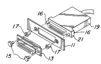
Referring to Figure 2, an exploded view of the
applicants' chassis panel connector system is shown. On the
inside face of panel 11, electrical connector receptacle 13
is secured thereto by bolt means 15. Bolts 15 thread into
fastener 17 which is clinched into the inside face of panel
11. The clinch head of fastener 17 is inserted flush with
the inside face of panel 11. Similarly, bolts 16 thread into
the standoff end of fastener 17 securing cable plug 19
thereto.
As shown more clearly in Figure 2a, fastener I7 includes
an elongated shank which passes through the mounting hole in
panel 11 and provides a standoff shoulder at its end for
holding the cable plug a given distance from receptacle 13.
Referring now to Figure 2a, fastener 17 includes a
knurled head 23 which is seated into the inside of metal
panel 11 flush with the inside face of the panel. The
20586~b
fastener includes clinch groove 25 which accepts the cold
flow of metal of panel 11 during insertion. The knurled
head 23 of the fastener secures it against rotation and is of
a proper diameter to prevent the bulging of metal into the D-
shaped cutout of panel 11 during insertion. The standoff
portion 27 of the fastener extends through the mounting hole
in panel 11 and provides a standoff shoulder 24 at the
lateral face at the end of the fastener which abuts the
flange of the cable plug 29. In the embodiment shown in this
figure, the standoff fastener is internally threaded all the
way through to receive fastening screw means from both ends.
Using this configuration, the receptacle and plug are both
releaseably and individually secured to the panel by three
fastening elements (two screws and the fastener standoff) on
each side of the cable. It should be obvious to those of
ordinary skill in the art that the standoff end of fastener
17 may include an extending threaded stud, rather than an
internal thread. The stud would cooperate with nut means on
the opposite side of the plug flange for attachment.
It will be readily apparent to those of ordinary skill
in the art from the mechanical relations described above that
the clinched head of fastener 17 at one end is in an abutting
relationship to receptacle 13, while the opposite end of the
fastener presents a flat lateral surface forming a
shoulder 24 which abuts flange 21 of plug 19. Because the
fastener does not abut the outside face of the panel, the
distance _ as shown in Figure 2a between the receptacle and
plug flange 21 is always equal to the length of fastener 17
regardless of the thickness of panel 11. Also, while the
preferred embodiment shows the head of the fastener 17
installed flush with the inside face of the panel, it may be
desirable in some applications to have the head protrude
slightly from the inside face. This will also result in the
2058606
proper spacing between the receptacle and plug flanges,
regardless of panel thickness so long as the fastener is
installed so that the protruding head is always the same
distance from the inside face of the panel.
Figures 3, 4 and 5 show alternate embodiments of the
present invention which include a clinch-type standoff
fastener with a grooved shank which extends beyond the
shoulder. As shown in these figures, these embodiments are
used with plugs having side clasps 31 which clip into the
grooves 33 at the end of the standoff.
It should be understood that the above description
discloses specific embodiments of the present invention and
are for purposes of illustration only. There may be other
modifications and changes obvious to those of ordinary skill
in the art which fall within the scope of the present
invention which should be limited only by the following
claims and their legal equivalents.