Note: Descriptions are shown in the official language in which they were submitted.
8 ~ ~}q'@~ 2 ~
BATTERIES WITH TESTE~ LABEL
Background of the Invention
This invention relates to batteries that have a tester
included in the label on the battery.
Some typical battery testers are multilayer strips.
There is generally a substrate layer onto which is deposited
an electrically conductive layer that has terminal end
portions. Also disposed on the substrate is a thermally
sensitive material. This material changes color when heated
and is in thermally transferable contact with the
electrically conductive layer. When the terminals of the
tester strip are placed in contact with the corresponding
terminals of a battery heat will be generated in the
conductive layer. The amount of heat generated is
proportional to the remaining power of the battery. The
heat is then transferred to the thermally sensitive material
causing it to change color. These tester strips are
available individually and in association with a package
containing the batteries.
One disadvantage with the currently available tester
strips is that the strip or package can become separated
from the batterie~ to be tested. Because of their ~hape and
style, the testing strips can be easily misplaced or discarded
as trash. Thus, when a need arises to test batteries, it may be
difficult to locate the tester strips. Also, the individual
tester strips are difficult to use.
In view of these disadvantages, a tester in close
association with the batteries to be tested i~ desired.
Summary of the Invention
This in~ention is a battery to which is attached a label
that contains a tester for the battery. The label is comprised
of a tester circuit that ha~ a first end to make direct contact
with a first terminal of the battery and a second end to make
direct contact with a second te ;nAl of the battery. These
ends are electrically connected to each other via an area of
controlled resistivity. The tester circuit is insulated from
the battery terminals except for the first and second terminal
contact ends. An indicating material is dispo~ed over and in
responsive contact with the area of controlled re~istivity of
the tester circuit.
In another aspect, this invention is a battery to which is
attached a label that contains a tester for the battery. The
label is comprised of:
20~P'?~
EBC-SP-OO91
.,.
a) a tester circuit comprised of an electrically
conductive material, and that has a first
terminal contact end and a second terminal
contact end connected to each other via an
area of controlled resistivity;
b) an indicating material disposed in responsive
contact with the area of controlled
resistivity of the tester circuit; and
c) a first terminal connector that connects the
first terminal contact end of the tester
circuit with a first terminal of the battery,
and a second terminal connector that connects
the second terminal contact end of the tester
circuit with a second terminal of the battery,
which terminal has a polarity opposite that of
the first terminal;
wherein at least one of the terminal contact
ends of the tester circuit is positioned out
of contact with its respective terminal
connector to provide an open tester circuit.
EBC-SP-OO91
In yet another aspect, this invention is a battery to
which is attached a label that comprises means for testing
the capacity of the battery and a means for indicating the
capacity of the battery. The testing means comprises means
5 for completing a circuit between the terminals of the
battery. The means for indicating the capacity of the
battery is in responsive contact with the means for testing
the capacity of the battery.
In still yet another aspect this invention is a process
for attaching a 12~el comprised of a tester for a battery to
a battery, comprising the steps of: -
a) applying a conductive layer to a nonconductive
base film layer, wherein the conductive layer
has first and second terminal contact ends that
are electrically connected to each other via an
area of controlled resistivity;
b) placing an indicating material in responsive
contact with the area of controlled
resistivity; and
c) adhering the surface of the nonconductive base
film layer opposite the surface on which the
-- 4
2 ~ J ~
EBC-SP-OO91
~ ..,~
conductive layer is deposited to the housing of
the battery.
The batteries of this invention have testers built into
the label so that whenever it is desired, the battery can be
5 tested. The batteries are easily tested by completing the
tester circuit in the label, and without the use of
components not associated with the battery or label.
Brief Description of the Drawinqs
Figure lA shows an exploded view of a multilayered
lQ label that has a single switch area, and Figures lB and lC
show the switch area.
Figure 2 shows an exploded view of a multilayered label
that has two switch areas.
Figure 3 shows an alternative embodiment of the dual
15 switch multilayered label.
Figure 4 shows an alternative embodiment of the dual
switch multilayered label.
Figure 5 shows an alternative embodiment of the dual
switch multilayered label.
2~ 728
Figure 6A shows a battery to which is attached a tester
label, and Figure 6B shows a front view of an assembled
label.
Figure 7A shows the area of contact between the tester
5 circuit and a terminal of the battery, and 7B is an
enlargement of that area.
Figure 8 shows a two-ply label containing a tester
circuit for a battery.
Figure 9 shows a stepwise method for making a label
10 with a testér circuit for a battery.
Figure 10 shows an alternative stepwise method for
making a label with a tester circuit for a battery.
Detailed Description of the Invention
The batteries useful in this invention are primary or
15 secondary batteries that have positive and negative
terminals. The batteries are generally comprised of an
anode, a cathode and electrolyte contained in a sealed
housing. The housing typically has an opening in one end
that is sealed and closed with a cover. This cover is
usually in electrical contact with either the cathode or
anode to provide a terminal of the battery.
-- 6
7 ~ ~ r
EBC-SP-OO91
The label is comprised of a means for testing the
capacity of the battery. This means is comprised of a means
for completing the circuit between the terminals of the
battery, a means for responding to the capacity of the
battery and a means for indicating the capacity of the
battery. The means for completing the circuit can be a
tester circuit that is comprised of an electrically
conductive material. The electrically conductive material
can be a metallic foil, or a metallized plastic layer.
Other examples include electrically conductive paints or
inks, such as those that contain graphite, c-~rbon or metals
or combinations thereof as the conductive materials. The
electrically conductive material is configured to have first
and second ends that are connected to each other via an area
of controlled resistivity. The first end is provided to
make contact with a first terminal of the battery, and the
second end is provided to make contact with a second
terminal of the battery. These terminal contact ends are or
will be connected to the terminals of the battery to
complete the tester circuit. Thus, when the tester circuit
is completed, electric current can flow through the area of
controlled resistivity. By "controlled resistivity" is
meant that the resistance is controlled to be within the
range to activate the responsive means.
2~ 't
EBC-SP-OO91
._
The resistance in the area of controlled resistivity
can vary or it can be constant. In one embodiment it is
desired to have a varying resistance to indicate relative
remaining useful life of a battery. For example, the
current flowing through the tester circuit will generate a
specific temperature. The temperature achieved will be
proportional to the amount of current supplied by the
battery. Thus, the area of controlled resistivity can be
tapered or of varying thicknesses to achieve a temperature
gradient. Alternatively, the area can be of constant width
and constant thickness. A further alternative could involve
the use of different conductive materials having different
resistivities in the area of controlled resistivity. In
addition, when using thermochromic materials, materials
activated at different temperatures could be used along an
area of constant resistance, or continuous or discontinuous
segments of a thermochromic material could be used along an
area of variable resistance.
The testing means can be further comprised of
means for connecting the tester circuit to the terminals of
the battery. This means can be terminal connectors that
connect the battery terminals with the terminal contact ends
of the tester circuit. The terminal contact ends of the
tester circuit can be in direct contact with the terminals
of the battery. However, this is only desirable when the
J~~ ~IJ
EBC-SP-OO91
~"_
circuit will place a very low drain on the battery so that
the battery is not prematurely discharged.
Preferably, either one or both terminal contact ends of
the circuit are out of contact with the terminals of the
battery so that the tester circuit is open. In this
embodiment, the testing means is further comprised of means
for switching the tester circuit on. The tester circuit
could have one or more switches. In a preferred embodiment
of the invention either the anode or cathode is in
electrical contact with the conductive housing of the
battery. In this embodiment, one of the terminal contact
ends of the tester circuit can be connected to the housing,
or positioned out of contact with the housing, for example
by a small opening in a layer disposed between the housing
and the end of the tester circuit. This opening can act as
a switch for the tester circuit. By forcing the terminal
contact end into contact with the housing through the
opening, the switch is closed and the tester circuit is
completed to test the battery. This contact can be
conveniently made by applying finger or thumb pressure to
the switch areas.
It is also desirable that the label comprise one or two
terminal connectors that are in contact with the battery
terminals. When the tester circuit is used, the terminal
:2 ~
EBC-SP-OO91
contact ends of the tester circuit will be in contact with
these terminal connectors. These terminal connectors can be
in the form of conductive tabs. In one embodiment, a
conductive cover acts as one terminal for the battery and
one of the conductive tabs is in electrical contact with
this cover.
The testing means further comprises a means for
indicating the capacity of the battery. The indicating
means will be in responsive contact with the area of
controlled resistivity and will respond to and indicate a
state that is present in that area. For example, a
temperature will be generated in that area when a current
flows through the tester circuit. Also, the current itself
can indicate such a state. If the indicating means will be
a thermally sensitive material, then it is in thermally
transferable contact with the area of controlled
resistivity. If the indicating means will be an electrical
field or voltage sensitive material, then the indicating
means will be in electrical contact with the area of
controlled resistivity. The indicating means will indicate
to the consumer what the capacity of the battery. This
indication can be qualitative such as a "good" or "bad"
reading, or quantitative such as a remaining percentage of
useful life.
-- 10 --
EBC-SP-OOsl
In one embodiment, the indicating means can be a
thermally sensitive material that is in thermally
transferable contact with the area of controlled resistivity
of the tester circuit. Thus, the heat generated in the area
of controlled resistivity in the tester circuit can be
transferred to the thermally sensitive material. The
thermally sensitive materials change color in response to a
temperature change. The material is readily viewable to a
consumer and so the consumer, based on the color change, can
determine whether the battery is good or needs to be
replaced. Examples of such thermally sensitive materials
are liquid crystal materials and thermochromic inks. The
indicating material can be used singly or in combination.
For example, in one embodiment different layers of the
indicating material are employed. The layers are activated
at different temperatures or states and can be designed to
change different colors at different temperatures. For
example, the layer of material activated at the highest
temperature will preferably be the bottom layer, and the
upper layers are arranged in decreasing temperature of
activation with the lowest temperature material in the top
layer.
Examples of suitable liquid crystal materials are of
the cholesteric type, such as cholesteryl oleate,
cholesteryl chloride, cholesteryl caprylate and the like.
7 ~ ~
Examples of suitable thermochromic inks include those
comprised of a dye, developer and desensitizing agent that are
disclosed in U.S. Patent 4,835,475. Inks can be obtained from
Japan Capsule Products and Sakura Colour Products Corp.
In another embodiment, the indicating and responding means
can be materials that respond to a voltage change or electric
field. These materials are responsive directly to the remaining
capacity of the battery as the current flows through the tester
circuit and so will be disposed in electrically responsive
contact with the area of controlled resistivity. Materials for
this purpose are known as electrochromic materials and are
commercially available from the Donnelly Corporation, for
example.
The labels useful in this invention can also comprise
additional insulative layers, printing layers, protective layers
and the like. Suitable materials for use as the different
layers are those typically used in battery labels and include
plasticized or unplasticized polyvinyl chloride (UPVC), metallic
films, paper and the like and they are prepared by known
methods, such as laminating the layers together. The label can
be attached to the battery by the use of an
adhesive. The label can be in the form of
- 12 -
EBC-SP-OOgl
_
individual sheets which will have a seam or in the form of a
shrinkable tube in which a battery is encased.
A preferred tester label is comprised of a base
insulative layer adhered to the housing of the battery. The
housing is in electrical contact with either the anode or
cathode of the battery. The insulative layer has an opening
in it. The tester circuit is placed on the surface of this
insulator. One of the terminal contact ends of the circuit
is aligned with the opening in the insulator. The other
terminal contact end of the circuit is in contact with the
terminal of the battery that is not in contact with the
housing. The indicating material is placed over the area of
controlled resistivity of the circuit. The indicating
material can be placed directly on the tester circuit or it
can be placed on a separate layer that is placed over the
tester circuit. Preferably, the indicating material is a
thermochromic ink and is in thermally transferable contact
with the area of controlled resistivity. Finally, a
protective layer is placed over the indicating material.
The type of protective layer is selected so that the
indicating material can be observed by the user. To test
the battery, the user will press the label at the point
above the opening in the insulator layer to establish
contact between the terminal contact end of the circuit and
the conductive battery housing. As the circuit is
- 13 -
2 ~
EBC-SP-OO91
,_
completed, a temperature will be generated in the area of
controlled resistivity which will be transferred to the
indicating material. If the desired temperature is reached,
the indicating material will so indicate and the user can
determine the amount of capacity remaining in the battery.
To prepare the individual sheet labels, a shrinkable
plastic film can be printed with a thermally sensitive
material in a test window area. Any graphics to be included
can also be printed on this film. On the reverse side of
this film the electrically conductive tester circuit is
printed, and an insulative layer is placed over this
conductive layer. The insulative layer prevents the
conductive layer from contacting the battery housing and
provides thermal and electrical insulation. The insulative
layer can completely cover the conductive layer, and
terminal connectors can be used to connect the battery
terminals with the terminal contact ends of the tester
circuit. Alternatively, openings can be left in the
insulative layer through which the conductive portion of the
tester circuit can be directly connected to the terminals of
the battery. An adhesive is added to the back of the label,
except for the portion in which the tester circuit will
contact the terminals. The tester circuit can also be
printed on a continuous layer of adhesive. The adhesive
side of the label is then joined to a releasable material
- 14 -
r3 . "
EBC-SP-OO91
such as a silicone paper web to form a label carrier. The
labels can then be die cut and converted to rolls ready for
use.
To prepare the labels on a shrinkable tube, after
forming the label as generally described above the label is
placed around a mandrel and welded lengthwise to form a
tube. The tube is then wound on a roll and is ready for
use.
In forming the labels, it is desirable that the
insulative layers be built up around any openings between
the battery terminals and the ends of the tester circuit.
This increased thickness will assist in preventing
accidental activation of the tester and resultant premature
discharge of the battery.
In a preferred method, unplasticized polyvinyl chloride
(UPVC) film can be metallized, e.g., aluminized, on one
surface. The UPVC film will provide an insulative layer and
the metallized layer can provide the conductive layer of the
label. Portions of the conductive layer can be removed to
establish positive and negative terminal contact ends of the
tester circuit and an area of controlled resistivity. The
portions can be removed by chemical etching or by photo
resist techniques. Alternatively, the deposition of the
_ EBC-SP-OO91
metallic layer can be done in the desired tester circuit
pattern. Another layer of insulation, such as an additional
PVC or a W -cured coating, such as those employing epoxy
resin, is deposited over the conductive layer. Areas of the
conductive layer are exposed through this insulative layer
to provide switch contact areas. One or more switch areas
can be provided. Advantageously, a relatively thick layer
of additional insulative material can be placed around the
switch areas to increase the distance needed to close the
switch and thus to ensure against inadvertent closure. A
foaming ink is suitable for this purpose. This insulative
layer can also be placed over the area of controlled
resistivity. An adhesive layer can then be placed over this
insulative layer. The adhesive layer will have openings in
it so that the conductive layer can contact the terminals of
the battery. This partial label can then be laminated to a
carrier web, such as silicone-coated paper.
On the other surface of the UPVC layer is deposited an
indicating material. The preferred indicating material for
this embodiment is thermally sensitive, such as a
thermochromic ink. This material is placed over the area of
controlled resistivity of the tester circuit. This outer
layer can also contain printing and graphics. The final
layer is a protective coating or film deposited over the
indicating material.
- 16 -
2 ~
EBC-SP-0091
, ,,
The layers and steps described above can be altered or
reversed in many ways to provide the label with a tester
circuit .
Referring to the Figures, Figure lA shows an exploded
view of a tester label 1. Insulative layer 5 has opening 7.
On one side of insulative layer 5 is adhesive layer 3. This
side of the label 5 will be adhered to the conductive
housing of a battery. On the surface of insulative layer 5
opposite the surface containing adhesive layer 3, is a
tester circuit 10. The tester circuit 10 can be located
directly on the surface of insulative layer 5. The tester
circuit 10 is comprised of an electrically conductive
material and has a first terminal contact end 12 disposed
over opening 7 in the insulator layer 5. Connected to the
first terminal contact end 12 is an area of controlled
resistivity 14. This area is connected to the second
terminal contact end in the form of tab 15 that can be
placed in contact with a terminal of the battery. Over the
tester circuit 10 is disposed label substrate 17. This
layer comprises thermally sensitive material 19. This layer
can also contain printing and can be made of plastic. This
layer further comprises switch area 20 that is aligned with
the first terminal contact end 12 and opening 7. Thus, the
tester circuit 10 can be completed by establishing contact
- 17 -
7,,,s, ~3
EBC-SP-0091
between first terminal contact end 12 through opening 7 to a
conductive battery housing by depressing switch area 20.
The thermally sensitive material 19 is disposed in thermally
transferable contact with the area of increasing resistivity
14 of tester circuit 10. Optionally, protective layer 18
can be placed over label substrate layer 17. Each of the
individual layers can range in thickness from about 0.S to
about 2 mils (i.e. from about 0.0005 to about 0.002 inch, or
from about 12 to about S0 microns).
Figure lB shows a side view of a portion of an
assembled label attached to a battery. Label 1 has
insulative layer 5 adhered to can 2 by adhesive layer 3.
Insulative ~ayer 5 has opening 7. Next to the insulative
layer 5 is end 12 of the tester circuit 10. The label 1 is
completed with label substrate layer 17 next to tester
circuit layer 11 and has protective layer 18 disposed on top
of it.
In Figure lC, the tester label 1 is activated by
depressing the label at the switch area 20 over opening 7.
Thus, end 12 of tester circuit 10 is placed in contact with
can 3.
In Figure 2, label 1 has the same adhesive layer 3, the
same label substrate layer 17, and optional protective layer
- 18 -
2 ~ ,7 ~
EBC-SP-OOgl
.~_
18 as the label in Figure 1. Insulative layer 6 in Figure
2, has an opening 8 and a tab 19. An additional insulative
layer 21 is disposed on one surface of the first insulative
layer 6. This additional insulative layer 21 has an opening
24 aligned with opening 8 in the first insulative layer 6,
and a second opening 25 aligned with a portion of the tab
19. Over the second insulative layer 21 is disposed tester
circuit 28. This tester circuit has a first terminal
contact end 29 aligned with opening 24 in the second
insulative layer 21 and a second terminal contact end 30
aligned with the second opening 25 in the second insulative
layer 21. The tester circuit 28 has an area of controlled
resistivity 32 connecting first terminal contact end 29 and
second terminal contact end 30. Label substrate layer 17
contains thermally sensitive material 22 in alignment with
the tester circuit area 32. The label substrate layer 17
has two switch areas 33 and 34. Switch area 33 is aligned
with the first terminal contact end 29 of the tester circuit
28, and switch area 34 is aligned with the second terminal
contact end 30 of tester circuit 28.
In Figure 3, label 1 has the same protective layer 18,
adhesive layer 3 and label substrate layer 17 as shown in
the other figures. Additionally, the label 1 has an
insulative layer 36 having a positive terminal connector 38
and a negative terminal connector 39. Positive terminal
- 19 -
2~ 7~
EBC-SP-0091
connector 38 has a tab 40 that will contact the positive
terminal of the battery, and negative terminal connector 39
has a tab 41 that will contact the negative terminal of the
battery. Next to insulative layer 36 is disposed a second
insulative layer 37. This insulative layer 37 has a first
opening 42 aligned with the positive terminal connector 38,
and a second opening 43 aligned with the negative terminal
connector 39. The next layer 44 in label 1 contains the
tester circuit 45 that has first terminal contact end 47,
and second terminal contact end 48 connected to each other
via an area of controlled resistivity 50. The first
terminal contact end 47 is aligned with the first opening 42
in insulative layer 37, and the second terminal contact end
48 is aligned with the second opening 43. Label substrate
17 which is disposed over tester circuit layer 44 has a
first switch area 51 and a second switch area 52, and has
thermally sensitive material 49. The first switch area 51
is aligned with first terminal contact end 47 of tester
circuit 45, and the second switch area 52 is aligned with
second terminal contact end 48. Because insulative layer 37
has openings 42 and 43, tester circuit 45 is open. Both
contact ends 47 and 48 are out of contact with the battery
terminals. By pressing both switch areas 51 and 52,
terminal contact ends 47 and 48 can be placed in contact
with terminal connectors 38 and 39 through openings 42 and
43 to complete the tester circuit 45.
- 20 -
n ~ ~ ~?,
EBC-SP-0091
The label 1 depicted in Figure 4 has the same layers as
the label in Figure 3. Area of controlled resistivity 50
and thermally sensitive material 56 in Figure 4 are
configured to run axially along the side of the battery to
be labelled.
The label 1 depicted in Figure 5 has the same layers
and tester circuit configuration as the label 1 in Figure 4.
The label 1 in Figure 5 has an insulative layer 57 that
contains an opening 58 and a negative terminal connector 39.
Opening 58 permits contact between end 47 of tester circuit
55 and the housing of a battery to be labelled.
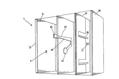
Figure 6A shows a front view of a fully assembled
label 1. On label 1, the thermally sensitive material 60 is
visible and will run axially along the side of the battery.
Switch areas 62 and 63 are also visible. Tab 65 of tester
circuit 61 can be seen to extend beyond the length of
label 1.
In Figure 6B, label 1 of Figure 6A has been adhered to
a battery 64. Terminal contact tab 65 is shown as extending
over and in contact with the bottom 66 of battery 64. In
this tab configuration, it can be desirable to have a
recessed area in the battery can bottom for the tab to rest.
2~
_ EBC-SP-0091
Switch areas 62 and 63 are shown to be on diametrically
opposite sides of the battery 64 and can be readily
activated by thumb and forefinger pressure.
In Figures 7A and 7B, the bottom of a battery and the
tab contact between the tester circuit in the label and a
battery terminal are shown. In 7A, the battery has
container 70 with opening 72. The opening 72 is closed with
first cover 73 that contacts anode current collector 75.
Cover 73 is sealed and secured to container 70 by seal 71.
Insulative annular washer 74 is placed over the opening 72
in container 70. Negative cover 76 is disposed over the
annular washer 74 and is in contact with the anode current
collector 75 to provide the negative terminal for the
battery. Label substrate end 86 of label 80 extends over
onto negative cover 76.
In 7B, the encircled portion of Figure 7A is enlarged.
The label 80 has insulative layer 81 disposed next to
container 70. The terminal contact tab 82 is an extension
of the tester circuit of the label, and extends over and
into contact with cover 76 at area 83. The label substrate
end 86 extends completely over terminal contact tab 82 to
conceal it. To complete labelling of the battery, the
extension of label substrate 86 is heat-shrunk over and
EBC-SP-0091
,_
around the periphery of cover 76 to insure good electrical
contact between contact tab 82 and cover 76.
In Figure 8 a two-ply label is shown. Label 90 has
base insulative film 91 with opening 92 and tester circuit
93. Tester circuit 93 has terminal contact tab 94 , area of
controlled resistivity 9S and terminal contact end 96.
Protective layer 97 is placed over base film layer 91. As
the label 90 is applied onto a battery, opening 92 will be
aligned with terminal contact end 96.
In Figure 9, the steps for making the label with a
tester are shown. In Steps 1 to 6, the label is viewed from
the backside and in Steps 7 to 9 the label is viewed from
the front side. In step 1, a base film layer 101 of PVC is
aluminized. In Step 2, a portion 102 of the aluminum is
removed in the pattern of the tester circuit 103. Next, an
electrical insulator is applied in Step 3 onto the
aluminized surface 105 with ends 106 and 107 exposed to
provide contact with the terminals of the battery. Extra
insulation 108 is applied in Step 4 to area 104 of the
tester circuit 103 and ends 106 and 107. In Step 5, a
pressure sensitive adhesive 109 is applied to the surface of
the label, and in Step 6 the label is applied to a silicone
coated paper 110. In Step 7, the opposite side of the base
PVC film 101 is printed with the label graphics 111. In
- 23 -
2 ~
~_ EBC-SP-0091
Step 8, the thermochromic ink 112 is placed over the area
104 of the tester circuit 103, and a protective film 113 is
applied over the label. Finally, in Step 9, the label is
die cut at points 114 to provide the individual labels.
The steps can be reversed as shown in Figure 10 with
the outer protective layer forming the initial layer. The
label is viewed from the back or the battery side. In Step
1, the protective film 121 is formed. In Step 2, the
thermochromic ink 122 is placed on the film. The label is
printed with graphics 123 in Step 3, and is laminated to
aluminized PVC in Step 4. The aluminized surface 124 is on
the surface of the PVC opposite of the surface next to the
protective film 121. In Step 5 the aluminized layer is
etched in the tester circuit pattern 125 with area of
controlled resistivity 126. In Step 6 an electrical
insulator is applied over the aluminized surface 124 of the
PVC film. Ends 127 and 128 are exposed to provide terminal
contact ends for the tester circuit. In Step 7 additional
insulation is placed around area 126 and ends 127 and 128 of
the tester circuit. Adhesive is applied over the insulator
in Step 8 and the label strip is laminated to a silicone
coated paper support 129 in Step 9. Finally, In Step 10 the
labels are die cut at 130 to the proper size.
- 24 -
EBC-SP-OO91
The tester circuit shown in these Figures can of course
be varied. Also the portion of the metallized surface can
be exposed at different areas to provide different switch
areas. To provide shrink tube labels, the labels can be
formed according to the above steps and then applied around
a mandrel and welded to form a tube.
- 2S -