Language selection

Search

Patent 2058863 Summary

Third-party information liability

Some of the information on this Web page has been provided by external sources. The Government of Canada is not responsible for the accuracy, reliability or currency of the information supplied by external sources. Users wishing to rely upon this information should consult directly with the source of the information. Content provided by external sources is not subject to official languages, privacy and accessibility requirements.

Claims and Abstract availability

Any discrepancies in the text and image of the Claims and Abstract are due to differing posting times. Text of the Claims and Abstract are posted:

  • At the time the application is open to public inspection;
  • At the time of issue of the patent (grant).
(12) Patent: (11) CA 2058863
(54) English Title: GOLF DRIVING MAT
(54) French Title: PLATE-FORME DE GOLF
Status: Expired
Bibliographic Data
(51) International Patent Classification (IPC):
  • A63B 57/10 (2015.01)
  • A63B 57/00 (2015.01)
  • A63B 69/36 (2006.01)
(72) Inventors :
  • HOOPER, MICHAEL (Canada)
(73) Owners :
  • 766089 ALBERTA LTD. (Canada)
(71) Applicants :
(74) Agent: BENNETT JONES LLP
(74) Associate agent:
(45) Issued: 1999-11-02
(22) Filed Date: 1992-01-07
(41) Open to Public Inspection: 1993-07-08
Examination requested: 1994-05-20
Availability of licence: N/A
(25) Language of filing: English

Patent Cooperation Treaty (PCT): No

(30) Application Priority Data: None

Abstracts

English Abstract


The invention relates to a golf driving mat comprising
a plurality of panel members assembled in edge-to-edge
abutting relationship, the panel members having releasable
engagement means formed on the edges thereof for
interlocking engagement of adjacent panel members, thereby
permitting removal and replacement of panel members
demonstrating wear.


Claims

Note: Claims are shown in the official language in which they were submitted.


THE EMBODIMENTS OF THE INVENTION IN WHICH AN
EXCLUSIVE PROPERTY OR PRIVILEGE IS CLAIMED ARE DEFINED AS
FOLLOWS:
1. A mat comprising:
an outer frame having a continuous outer perimeter;
a panel assembly disposed within said frame;
said panel assembly including a plurality of panels releasably joined with
adjacent panels;
each of said panels including a base having a plurality of engagement means
on each of the edges thereof for interlocking engagement with adjacent panels;
said engagement means on said panels extending vertically in relation to
said base for permitting vertical separation of one panel from another;
said frame including a plurality of engagement means on the internal
perimeter thereof for interlocking engagement with the engagement means of
said
panels; and,
bristles anchored within said base in an upstanding relationship thereto for
thereby forming a simulated grass turf thereon.
2. The mat of claim 1 wherein said engagement means on said panels
comprises fingers and grooves.
3. The mat of claim 1 wherein said engagement means are generally
rectangular in shape.
-8-


4. The mat of claim 1 further including a golf tee.
5. A panel assembly for use with an outer frame of a mat, said panel assembly
comprising a plurality of panels releasably joined with adjacent panels, each
of said
panels including a base having a plurality of engagement means on the edges
thereof for interlocking engagement with adjacent panels, said engagement
means
extending transversely in relation to said base for permitting transverse
separation
of one panel from another and from said outer frame, and bristles anchored
within
said base in an upstanding relationship thereto to form a brushed mat surface.
6. The panel assembly of claim 5 wherein said engagement means on said
panels comprises fingers and grooves.
7. The panel assembly of claim 5 wherein said engagement means are
generally rectangular in shape.
8. The panel assembly of claim 6 wherein said fingers and grooves are
generally rectangular in shape.
9. The panel assembly of claim 5 further including a golf tee.
10. In a mat having a frame with an outer perimeter, a panel assembly disposed
within said frame comprises a plurality of panels releasably joined with
adjacent
panels, each of said panels including a base having a plurality of engagement
means
-9-


on the edges thereof for interlocking engagement with adjacent panels, said
engagement means extending vertically in relation to said base for permitting
vertical separation of one panel from another, and bristles extending from
said base
in an upstanding relationship thereto to form a brush surface.
11. The mat of claim 10 wherein said plurality of engagement means are
adapted for interlocking engagement with said outer perimeter of said frame,
and
for permitting vertical separation of said panels from said frame.
12. The mat of claim 10 wherein said engagement means on said panels
comprises fingers and grooves.
13. The mat of claim 11 wherein said engagement means on said panels
comprises fingers and grooves
14. The mat of claim 10 wherein said engagement means are generally
rectangular in shape.
15. The mat of claim 11 wherein said engagement means are generally
rectangular in shape.
16. The mat of claim 10 further including a golf tee secured to said base of a
panel.
-10-

Description

Note: Descriptions are shown in the official language in which they were submitted.


2p 5~8 63 __
This invention relates to a golf driving mat and, more
particularly, to a mat simulating turf, in which the mat
comprises a plur~~lity of interlocking panels.
Golf driving ranges, which provide facilities for
practice driving) normally are equipped with simulated grass
mats at each dri~Jing station, in which upstanding bristles,
embedded in a backing, provide a surface similar to the turf
normally encountered on fairways and tee stations at golf
courses.
Tee-off conditions are duplicated by the incorporation
of an upstanding flexible tube or 'tee' extending above the
surface of the s~_mulated turf, upon which the practice ball
may be positioned for driving. The tee is normally
comprised of a flanged flexible tubular element, inserted
~ upwardly through an aperture formed in the backing of the
mat.
Dimensional=ly, the mat is usually rectangular in shape,
perhaps six feet to the side, in order to freely accommodate
the user while assuming a practice position standing on the
mat addressing the ball so positioned on the tee.
As can be expected, the impact of the club head on the
bristles of thE~ mat ultimately results in the wearing or
breakdown of the mat in the vicinity of the club head
striking zone, which has heretofore necessitated the
replacement of the golf practice mat, with attendant cost.
_ 2 _


2 0 5 8 8 6 3 __..
In partial response to the wear problem, a golf
practice mat i~c depicted in United States Patent No.
3,467,391 to Ele~sh, in which groups of bristles or tufts are
replaceably mounted on the backing by means of anchoring
rods, thereby providing for replacement of the tufts when
necessary.
The structure of this invention addresses the wear
problem in a novel fashion, by providing a mat comprises of
interlocking panels which are readily assembled and allow
for mat upgrading by simple removal of the panel exhibiting
unacceptable weir, and its substitution with a replacement
panel.
In its preferred embodiment, the panels are formed of
molded plastic or an elastomeric substance such as hard
rubber, with interlocking finger elements formed on the
rectangular edges thereof, adapted f.or engagement with
adjacent panels.
Another embodiment includes a perimeter frame into
which the interlocking panels can be assembled, thereby to
ensure a firm surface on which the golfer positions himself
while driving.
Accordingly, it is a principle object of the invention
to provide a golf practice mat comprised of panel members
each adapted for replacement following unacr_.eptable wear
thereof .
- 3 -


20 588 6 3
It is a further object of the invention to provide a golf practice mat
comprising panel members having interlocking edge elements.
It is still a further object of the invention to provide a golf practice mat
comprising panel members assembled in a frame defining a perimeter adapted to
s securely retain the panel members in the desired configuration.
It is a fiuther object of the invention to provide an apparatus of the type
described which is characterized by a simplicity of design and possesses the
necessary ruggedness for durable and reliable use.
Additional. objects and advantages will become apparent from the following
io description taken in conjunction with the accompanying drawings, wherein:
Figure 1 is a perspective view of a panel member depicting the backing
plate, upstanding tufts comprising simulated turf and edge interlocking means;
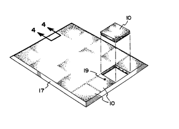
Figure 2 is a perspective view of the assembled mat, depicting the panels
secured within the perimeter frame;
is Figure 3 is a perspective view of a typical tee suitable for use with the
mat
of the subject invention; and,
Figure 4 is a partial enlarged perspective view taken along line 4-4 of Fig. 2
without the panel members.
Referring to the drawings with initial reference to figure 1, the panel
20 member 10 is depicted comprising a backing plate 11, of unitary material
such a~s
hard rubber or plastic, of desirably square configuration.
-4-
B


20 588 6 3
Regularly spaced rows of holes 12, formed in the upper
surface of the backing plate 11, receive the lower ends of a
plurality of groups or tufts of bristles 13, anchored
therein for example, by adhesive retention, in order to form
a mat surfar_e l~l. It will be appreciated that there are
many ways to anchor bristles 13 in hole 12, the indicated
use of adhesive is purely exemplary.
In the preferred embodiment depicted, a plurality of
grooves and fingE>rs 15 and 16, Figure 1, are formed on the
edges of the panel members 10, adapted to engage in
interlocking faahion with registering fingers and grooves
formed in adjacent panel members, thereby to rigidly lock
the panel members into a secure mat of desired dimensions.
A surrounding frame 1.7, Figure 2, dimensionally appropriate
to the desired mat size, engages the edges of the mat formed
by the assembled panel members by engagement of outstanding
finger members 7_5, with the registering grooves formed on
the perimeter edge of the mat, thereby retaining the frame
and panel member~~ in solid unitary fashion, as depicted.
The golf i;ee 19, Figures 2 and 3, r_onventionally
comprises an elongated tubular portion 20, and a disc-like
base portion 21, adapted to be inserted upwardly through a
hole formed in the mat. The tubular portion 20 will be of a
length sufficient= to extend beyond the brush surface of the
mat, in order to elevate the golf ball supported thereon in
- 5 -


20 588 6 3
a fashion similar to that of a conventional golf tee on a
grass tee station.
In assembly,. panel members 10 are conjoined by engaging
the groove and finger elements on adjacent edges of
registering pane=L members to form a mat assembly of desired
dimension and configuration. The frame members are then
assembled in per=meter fashion around the mat by engagement
of fingers formed on the frame, while registering grooves on
the perimeter edge of the assembled mat.
Consequent on excessive wear or other degradation
occurring to the bristles at any specific location on the
mat, as for example adjacent to the tee, the panel member or
members on which the brush wear has occurred can be lifted
upwardly and out of the assembly for replacement, the
remainder of the panel members remaining in place within the
frame .
While it ha~~ been found that fingers and grooves formed
in the edges of i~he molded panel members are most suitable,
other engagemeni:. means for securing adjacent panel members
will readily occur to those familiar with the art to which
this invention relates, such as spring clips engaging in
apertures formed in adjacent panels.
Further modifications and alternative embodiments of
the invention will be apparent to those skilled in the art
in view of the description.
- 6 -


2o5es s3
Accordingly,. the description is to be construed as
illustrative onJ.y arid is for the purpose of teaching those
skilled in the art, the manner of carrying out the
invention. It ~_s understood that the form of the invention
herewith shown and described is to be taken as the presently
preferred embodiment, and that various changes may be made
in the shape, size and general arrangement of the
components.

Representative Drawing
A single figure which represents the drawing illustrating the invention.
Administrative Status

For a clearer understanding of the status of the application/patent presented on this page, the site Disclaimer , as well as the definitions for Patent , Administrative Status , Maintenance Fee  and Payment History  should be consulted.

Administrative Status

Title Date
Forecasted Issue Date 1999-11-02
(22) Filed 1992-01-07
(41) Open to Public Inspection 1993-07-08
Examination Requested 1994-05-20
(45) Issued 1999-11-02
Expired 2012-01-07

Abandonment History

There is no abandonment history.

Payment History

Fee Type Anniversary Year Due Date Amount Paid Paid Date
Application Fee $0.00 1992-01-07
Maintenance Fee - Application - New Act 2 1994-01-07 $50.00 1994-01-06
Maintenance Fee - Application - New Act 3 1995-01-09 $50.00 1995-01-05
Maintenance Fee - Application - New Act 4 1996-01-08 $50.00 1996-01-04
Maintenance Fee - Application - New Act 5 1997-01-07 $75.00 1997-01-06
Maintenance Fee - Application - New Act 6 1998-01-07 $75.00 1997-12-11
Maintenance Fee - Application - New Act 7 1999-01-07 $150.00 1999-01-07
Registration of a document - section 124 $100.00 1999-03-17
Final Fee $300.00 1999-08-05
Maintenance Fee - Patent - New Act 8 2000-01-07 $150.00 1999-12-20
Maintenance Fee - Patent - New Act 9 2001-01-08 $150.00 2000-12-11
Maintenance Fee - Patent - New Act 10 2002-01-07 $200.00 2001-10-15
Maintenance Fee - Patent - New Act 11 2003-01-07 $200.00 2002-11-19
Registration of a document - section 124 $100.00 2003-01-29
Maintenance Fee - Patent - New Act 12 2004-01-07 $200.00 2003-08-20
Maintenance Fee - Patent - New Act 13 2005-01-07 $250.00 2004-11-03
Maintenance Fee - Patent - New Act 14 2006-01-09 $250.00 2006-01-03
Expired 2019 - Corrective payment/Section 78.6 $650.00 2006-09-08
Maintenance Fee - Patent - New Act 15 2007-01-08 $450.00 2006-11-08
Maintenance Fee - Patent - New Act 16 2008-01-07 $450.00 2007-10-23
Maintenance Fee - Patent - New Act 17 2009-01-07 $450.00 2008-12-05
Maintenance Fee - Patent - New Act 18 2010-01-07 $450.00 2009-12-18
Maintenance Fee - Patent - New Act 19 2011-01-07 $450.00 2010-11-29
Owners on Record

Note: Records showing the ownership history in alphabetical order.

Current Owners on Record
766089 ALBERTA LTD.
Past Owners on Record
HOOPER, MICHAEL
Past Owners that do not appear in the "Owners on Record" listing will appear in other documentation within the application.
Documents

To view selected files, please enter reCAPTCHA code :


To view images, click a link in the Document Description column. To download the documents, select one or more checkboxes in the first column and then click the "Download Selected in PDF format (Zip Archive)" or the "Download Selected as Single PDF" button.

List of published and non-published patent-specific documents on the CPD .

If you have any difficulty accessing content, you can call the Client Service Centre at 1-866-997-1936 or send them an e-mail at CIPO Client Service Centre.


Document
Description 
Date
(yyyy-mm-dd) 
Number of pages   Size of Image (KB) 
Representative Drawing 1999-10-25 1 9
Cover Page 1993-11-06 1 14
Abstract 1993-11-06 1 43
Claims 1993-11-06 1 38
Drawings 1993-11-06 1 48
Description 1993-11-06 6 249
Description 1999-03-10 6 190
Claims 1999-03-10 3 88
Drawings 1999-03-10 1 37
Representative Drawing 1998-09-29 1 20
Cover Page 1999-10-25 1 27
Correspondence 1999-08-05 1 33
Fees 2004-08-27 1 28
Fees 1999-12-20 1 33
Correspondence 2004-10-06 1 17
Fees 2002-11-19 1 27
Correspondence 2002-12-10 1 11
Correspondence 2002-12-10 1 13
Assignment 2003-01-29 1 44
Fees 2003-08-20 1 27
Correspondence 1997-08-19 1 1
Correspondence 1999-04-16 1 1
Correspondence 1998-07-21 1 2
Correspondence 1998-07-21 1 1
Fees 2000-12-11 1 38
Correspondence 2001-11-07 1 16
Correspondence 2001-11-07 1 13
Correspondence 2001-10-15 2 53
Fees 2001-11-23 2 64
Correspondence 2002-11-07 1 11
Fees 1999-01-07 1 35
Fees 2001-10-15 2 47
Prosecution-Amendment 2002-09-06 4 133
Fees 1997-12-11 1 26
Fees 2004-11-03 2 66
Correspondence 2004-08-27 1 31
Fees 2006-01-03 1 27
Prosecution-Amendment 2006-09-08 4 144
Correspondence 2006-10-20 1 14
Fees 2006-11-08 1 31
Fees 2007-10-23 1 35
Fees 2008-12-05 1 42
Fees 1997-01-06 2 52
Fees 1996-01-04 1 27
Correspondence 1994-04-18 1 12
Fees 1994-03-28 1 22
Fees 1994-01-06 1 19
Fees 1995-01-05 1 25
Prosecution Correspondence 1992-01-07 9 376
Office Letter 1997-02-05 2 71
Office Letter 1998-08-17 1 17
Examiner Requisition 1998-08-17 2 31
Examiner Requisition 1997-07-29 1 36
Correspondence Related to Formalities 1998-05-29 3 96
Correspondence Related to Formalities 1994-05-20 1 30
Office Letter 1994-07-04 1 35
Correspondence Related to Formalities 1997-07-18 2 47
Prosecution Correspondence 1999-02-11 4 219
Prosecution Correspondence 1999-02-11 3 92
Prosecution Correspondence 1998-05-29 4 98
Prosecution Correspondence 1994-07-25 1 44
Prosecution Correspondence 1994-07-25 1 36