Note: Descriptions are shown in the official language in which they were submitted.
20S9010
CONVECTION-RADIANT HEATED OVEN
FIELD OF THE INVENTION
This invention relates to ovens utilizing forced
convection heating, and, more particularly, to an oven
utilizing both radiant heat and an improved convection air
flow circulation.
BACKGROUND OF THE INVENTION
In the processing of food within an oven, it has long
been the most important desideratum that there be a uniform
distribution of heated air within the oven to insure
uniform heating or cooking of the food. Because an oven
contains a relatively large volume of air, it has proven to
be quite difficult to minimize temperature gradients and
hot spots within the oven, and, consequently, to avoid the
uneven application of heat to the food. There have been
numerous attempts at such minimization of uneven cooking
through oven designs wherein forced convection heating is
utilized in an effort to attain temperature uniformity.
These ovens have, in general, a heat source, such as a gas
or electric burner, and a blower which draws air to be
heated across the heat source to heat it and discharges the
air thus heated into the cooking chamber.
In U.S, patent 4,928,663 of Nevin et al there is shown
a forced convection oven wherein air heated in a combustion
chamber is directed into a blower assembly, which also
receives air from the oven chamber which is mixed with the
heated air, and the mixture is forced out into the oven
chamber., Thus, the blower assembly mixes currents or
streams of air, one of which is introduced into the blower
assembly from the front and the other of which is
introduced through the rear, and centrifugally discharges
the uniform temperature mixture into the oven chamber.
This is in contrast to the more common arrangement where
- 2059010
the two streams are mixed in the oven compartment where the
food is located.
In U.S. patent 5,016,606 of Himmel et al, the air is
heated by a burner externally of the oven and delivered to
a blower by means of a fire tube. The blower mixes the air
so delivered with return air from the oven chamber and
discharges the mixture into the oven chamber. In U.S.
patent 4,071,738 of Jenn et al, the air is heated after it
is blown into the oven chamber, thus the oven of this
lo patent utilizes both radiant heating and convection
heating, inasmuch as the burners or heaters are within the
oven chamber, however, the use of heating units within the
cooking chamber, as shown by Jenn et al, limits such use
to electrical heating elements.
Another type of convection heating oven utilizes jets
of heated air applied to the food being cooked. Such ovens
are shown in U.S. patents 4,474,498 of Smith and 4,626,661
of Henke, while U.S. patent 4,817,509 of Eric~son discloses
an arrangement where heated air is swirled over the food,
which is placed in close proximity to the blower. Another
arrangement utilizing a swirling action is shown in U.S.
patent 4,865,864 of Rijswijck. In some instances, the
nature of the food being cooked, such as certain types of
bread, for example, is such that jets of air or swirling
air can adversely affect or disturb the food. Thus, it is
desirable, in most cases, that there be a general
circulation of uniform temperature air which does not
disturb the food. The aforementioned Nevin et al patent is
directed to such a heating arrangement.
In all of the foregoing, with the exception of the
Jenn et al patent, radiant heating is not utilized, or it
is not a serious factor in the cooking process. Thus, even
though the prior art patents are aimed, in most cases, at
achieving uniformity of temperature throughout the volume
of the oven, they do not utilize radiant heating to
supplement the convection,heating with a consequent economy
20590 1 0
--4--
of operation of the oven. In addition, prior art
arrangements utilizing forced convection heating, in
general, apply the heated air directly to the blower from
the rear, thus all of the heated air is under forced
convection. Such ovens require somewhat elaborate
ducting to distribute the heated air more or less evenly
and to return the air to the burner or heater.
SUMMARY OF THE INVENTION
The present invention is directed to the achievement
of substantially uniform heating within an oven through
the combined use of both radiant and convection heating.
The invention in one broad aspect provides an oven
comprising a bottom wall, a top wall spaced from and
opposing the bottom wall, a first side wall joining the
top wall and the bottom wall, a second side wall opposing
the first side wall, a rear wall joining the top wall and
the bottom wall, and a front wall opposing the rear wall
for defining therebetween an oven chamber. The first
side wall and the second side wall each define therein an
upwardly extending channel and a pair of burners are
disposed below and spaced from the bottom wall. An air
duct is positioned between the bottom wall and the
burners, the air duct defining therein openings and the
air duct being in fluid communication with the oven
chamber. A fan is mounted adjacent to the air duct,
wherein air is heated by the burners, a portion of the
heated air being directed against the bottom wall, a
portion of the heated air being forced by the fan into
the oven chamber, and a portion of the heated air moving
into the oven chamber through the channels.
205901 0
-4a-
In an illustrative embodiment thereof the oven of
the invention comprises a burner box or heating chamber
utilizing gas flame heaters. Air to be heated is vented
into the burner box through a louvered oven front or kick
plate and is passed directly over the flames. Flame
spreaders located over the individual elongated burners
spread the flames across the underside of an oven bottom
shield which, in turn, heats the oven or cooking chamber
bottom, thereby supplying radiant heat to the food within
the oven. At the same time, the flame spreaders act in
the manner of baffles to direct the heated air to an
apertured bottom shield duct which extends horizontally
from the front toward the rear of the oven. The flame
spreaders, acting as baffles, also direct heated air
toward vertical recesses extending up the side walls
within the oven chamber so that heated convection air
passes from the bottom toward the top of the oven
chamber, and is drawn into the chamber by the action of a
convection fan mounted at the rear of the oven chamber
which creates a low pressure region and a high pressure
region. This slow convection is in contrast to the
convectional forced air convection heating, where the
heated air is blown out into the cooking chamber by the
convection of air.
'~
2059010
The heated air in the bottom shield duct is drawn into
a vertical convection duct to an opening in front of the
convection fan, which is, in this embodiment, the low
pressure side of the fan. The convection duct has,
immediately in front of the convection fan, a plurality of
apertures arranged in an approximately circular array
through which air within the oven chamher is drawn and is
mixed with the heated air in the convection duct. A
convection fan cover forms first and second laterally
extending air ducts through which the air mixture is passed
back into the oven chamber from the high pressure side of
the convection fan. Because ambient air is continually
being drawn into the heating chamber or burner box, used or
stale air is vented to the outside through exhaust ducts
and vents located at the top front of the oven assembly.
The oven of the present assembly, as described in the
foregoing, utilizes, in effect, three heating modes to
achieve a high degree of temperature uniformity throughout
the oven volume. In addition to the forced convection
heating in which the fan blows the air mixture into the
cooking chamber, the oven utilizes radiant heating and a
relatively slow convection heating from heated air passing
up the recesses in the side walls, all of which function to
achieve cooking of food at reduced times and temperatures,
with a conse~uent reduction in the tendency of the food to
dry out, and with a concomitant economy of operation.
The numerous features and advantages of the present
invention will be more readily apparent from the following
detailed description, read in conjunction with the
accompanying drawings.
BRIEF DESCRIPTION OF THE DRAWINGS
Fig. l is a perspective, partially cutaway view of an
oven embodying the principles of the invention;
Fig. 2 is a diagrammatic view of a portion of the oven
of Fig. 1;
2059010
Fig. 3 is a detailed side elevational cross sectional
view of an oven embodying the principles of the invention;
and
Fig. 4 is a front elevational view of the oven of Fig.
3.
D~T~ILED DESC~IPTION
In Fig. l there is shown a pre~erred embodiment of the
oven 10 of the invention in a partially cutaway perspective
10view, wherein the same numerals designate like parts
throughout the several drawings.
Oven 10 comprise~ ~n oven bottom or floor 11, a rear
wall 12, and side walls 13 and 14, only side wall 13 being
shown in Fig. l. Floor ll and walls 12, 13 and 14 define
15an oven cooking chamber along with fron~ and top walls, n~t
shown. First and second burners 16 and 17 are located
below oven bottom 11 and are spaced therefrom being
contained in a burner box 20. Burners 16 and 17, which
extend from the front of the oven toward the rear wall 12
20are preferably gas burners, however, they may,
alternatively, be electric elements. ~irst and second
shallow V-shaped flame spreaders 18 and 19 are located over
burners 16 and 17, respectively, and function to spread the
burner flames over a wide area below the oven bottom 11.
25An oven bottom shield 21 is located above burners 16 and 17
and below and spaced from the oven bottom 11 forming a heat
space 25. In use, the heated air in space 25 heats oven
bottom ll to supply radiant heat to the cooking chamber.
Shield 21 has openings 22 and 23 in which flame spreaders
3018 and 19 are respectively located and acts, in conjunction
with flame spreaders 18 and 19 to protect oven bottom 11
from direct contact with the flames from burners 16 and 17.
Located in the space 25 between the oven bottom 11 and
oven bottom shield 21 is a bottom shield duct 24 preferably
35of a hollow rectangular configuration which extends from
the front area of the oven toward the rear. Duct 24 has a
2059010
plurality of inlet vent holes 26, 26 on either side
thereof. As can be seen in Fig. 1, the width of flame
spreaders 18 and 19 is slightly less than their respective
openings 22 and 23, leaving four gaps, only two of which 2~
and 28 are shown, between the flame spreaders 18 and 19 and
the oven bottom shield 21. The gaps serve to permit heated
air to pass from below the oven bottom shield 21 into the
space between it and oven bottom 11. The heated air thus
passing through gap 28, for example, enters duct 24 through
the vent holes 26, 26, and, as will be apparent
hereinafter, passes through duct 24 toward the rear of the
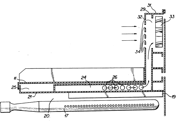
oven. Located at the rear of the interior of the oven lo
is a convection duct 29 of hollow rectangular~shape which
extends upward from the bottom of the furnace and is in
unobstructed communication with duct 24, as best seen in
Fig. 2. Referring to Fig. 2, it can be seen that duct 29
extends upwardly in front of a convection fan housing 31
having an opening 32 therein for air flow communication
between duct 29 and housing 31. A convection fan 33 is
located within housing 31 and serves, when operating, to
establish a low pressure region at opening 32. Thus an air
flow is created which draws air from the heating region 20
through gap 28 and corresponding gaps into duct 24 ~hrough
openings 26, 26 and then upward through duct 29. The ~ront
of duct 29 has a plurality of intake vent holes 34, 34
through which air passes from the oven chamber into duct
29, through opening 32, and into housing 31.
The pitch of the blades of fan 33 and the direction of
rotation are such that a high pressure region is created at
the outer ends of the fan blades and also behind the fan
and air drawn through opening 32 is directed out of housing
31 through laterally extending ducts 36 and 37, and, with
the aid of deflectors 38 and 39 is directed back into the
cooking chamber of oven 10. Thus, the ducts 24, 29, fan
33, and ducts 36 and 37 create a forced convection system
for the oven whereby air heated by the burners 16 and 17 is
2059010
-8-
mixed with air fr~m the oven and blown into the oven
adjacent the side walls thereof.
In addition to the forced convection heating
arrangement, as just described, the oven 10 also utilizes
a slow convection heating for achieving, in conjunction
with the radiant heating from the oven bottom and the
forced convection heating, a substantially uniform
temperature throughout the volume of the oven cooking
chamber. To this end, side wall 13 has a vertically
extending recessed portion 41 which is in communication
with the space 25 between oven bottom 11 and oven bottom
shield 21 into which heated air passes from gap 27 and
rises upwardly and into the cooking chamber as shown by the
arrows. A corresponding gap and recess in side wall 14,
not shown, also allows heated air to rise within the
chamber on the other side of the furnace. Thus, the oven
10 of Figs. 1 and 2 utilizes radiant heating, forced
convection heating, and a relatively slow convection
heating by the heated air rising up the recessed portions
of the side walls. The ratio of the convection heatinq to
radiant heating can be varied by variations in the
parameters of fan pitch and speed of rotation, the burner
temperature, and, to some extent, the amount of air drawn
into and discharged from the oven. In practice, a ratio of
sixty percent (60%) radiant heating to forty percent (40%)
convection heating has yielded excellent results in
achieving uniformity of heating.
Fig. 3 is a detailed side elevation view of an oven
cross-section wherein the oven 10 has a conventional hinged
door assembly 42 forming an oven front wall and having a
pull handle 43. Located below the door assembly 42 is a
louvered kick plate 44 through which ambient air is drawn
into the oven and into space 20 containing the burners 16
and 17, only 17 being shown in Fig. 3. If desired, air
~ilter means, not shown, may be placed in the space
immediately behind kick plate 44 to remove impurities that
20~90~ 0
may be in the incoming air. As was pointed out
hereinbefore, fan 33 creates a negative or reduced pressure
region which, through ducts 29 and 24, in communication
with the air heating region, i.e., burner box 20, thereby
insuring a continuous incoming stream of ambient air when
the oven is in operation.
Top member 47 of oven 10 has an exhaust duct 4~
located therein which communicates with the oven cooking
chamber and with the exterior through a vent trim 49 which
may be adjusted to control the volume of exhaust air being
vented from the oven to the exterior.
Fan 33 is driven by a motor 51, and, as pointed out
hereinbefore, the pitch of the blades of fan 33 and th~e
speed of rotation thereof as governed by motor 51 produce
a low pressure region at the opening 32. The speed of
rotation of motor 51 and the pitch of the blades of fan 33
are two of the parameters that can be varied to produce the
desired uniformity of heating within the cooking chamber
through variation of the convection currents. The cooking
chamber contains a food holding or supporting rack 52 for
supporting the food to be cooked.
Fig. 4 is a detailed front elevational view of the
oven 10 of Fig. 3, showing the relative locations and
spacings of the various parts, as well as their general
configuration. In addition, Fig. 4 shows the location of
an oven control panel 53.
In operation, when the oven 10 is turned on and
burners 16 and 17 are ignited, and with fan 33 rotating,
ambient air is drawn through louvered kick plate 44 into
the heat~ng ~hamber or burner box 20, and then, as
previously described, into duct 24 through openings 26, 26
and also up the recesses 41. At the same time, oven bottom
11 is heated, thus providing radiant heat. The heated air
in duct 24 passes into duct 29, where it is mixed with air
from the cooking chamber passing i~to duct 29 through
openings 34, 34 and the mixture passes through opening 32,
20S9010
--10--
and into ducts 36 and 37 from which it is directed
forcefully into the cooking chamber of the oven by
deflectors 38 and 39. Used or "stale" air is exhausted
through duct 48 to the outside. Thus, there is a constant
heating of incoming "fresh" air which continuously replaces
previously heated and used air. The combination of radiant
heating, slow convection up recesses 41 and forced
convection through ducts 36 and 37 produces a high degree
of uniformity of heating of food supported on rack 52,
which, as pointed out hereinbefore, can be optimized by
varying one or more of the parameters of air temperature,
fan pitch, and fan speed of rotation. Because the three
modes of heating produce a substantially uniform heating of
the food within the cooking chamber, the cooking time is
substantially reduced and, as a consequence, economy of
operation of the oven is improved.
The foregoing description has been directed to a
single preferred embodiment utilizing the principles of the
invention. Numerous variations and modifications may be
made by workers skilled in the art without departure from
the spirit and scope of the invention.