Note: Descriptions are shown in the official language in which they were submitted.
__ .. _ 2 - _. 20~_~~rl~
"TEST TUBE FOR BIOhOGICAL ANALYSES, PROVIDED WITH A
DEVICE FOR CHECKING EFFICIENCY AND POSITION, FOR
PHOTOMETRIC READINGS"
DESCRIPTION
The invention relates to a test tube for
biological analyses and in particular for blood tests,
for example measuring the erythrocyte seda_znentation rate
(or E.S.R.) and other tests and analyses that can be
performed with optical measuring instruments. With
equipment of this kind, use is generally made of test
tubes that may be of various shapes and sizes. To achieve
a good level of automation and eliminate all sources of
error, it is advisable to carry out a number of checks,
especially checking that 'test tubas are present and that
they have been correctly positioned in the instrument. In
addition, it is always advisable to check the efficiency
of the optical systems -(emitter--+--receiver)-, so -that -
errors of insertion and position of the test tubes are
r
not inadvertently made. With the invention, the check for
the presence of the test tube can in fact be made
- directly by the instrumentrs optical reading.sys~em.and
suitably controlled by a computer. The device of the
invention also serves to check on the exact position of
the test tube inside' the instrument, since a test tube
25. that is not.fully_inser~ed in_.ats seat can - if the fault
is not,reported - give rise to bad data readings which
may then. cause sometimes very serious problems and
~rroxs: Another useful aspect of the invention is that it
can a~xtomatiaally carry out a continuous and repeated
dheck on the speed and inertia of response of the ogtical
sensor , so ws to av~id errors in the readings and in the
results obtained from these. .
These and other objects and advantages will
becomA clear from the following more detailed
._ description.
Basically, the test tube for biological analyses,
W raking it possible to perform an optical inspection
CA 02059070 2002-10-28
20333-353
3
through the test tube itself and with a relative movement
between the optical system and the test tube, the latter
being between the components (emitter and receiver) of said
system, according to the invention possesses externally on
the base an optical prism that induces a sudden change in
the direction of the light beam of said optical system,
thereby giving rise to a "dark" signal in the receiver.
The optical prism can be an extension projecting
from a flat thickness forming the transparent base of the
test tube. The optical prism can be obtained directly from
the molding of the transparent material that forms the test
tube.
Advantageously the prism bounds a step formed
along the outer edge of the base of the test tube.
The invention may be summarized according to a
first aspect as a test tube apparatus for analyzing fluid,
the test tube comprising: a cylinder having walls
transparent to a beam of light passing through said cylinder
in a substantially radial direction, said cylinder has a
radial cross-sectional shape substantially similar to a
parallelogram; optical prism means for receiving the radial
beam of light on a first side and substantially barring the
radial beam of light from exiting said optical prism means
on a second side, said second side being substantially
radially opposite said first side, said optical prism means
being positioned on an axial end of said cylinder.
According to another aspect the invention provides
an optical analysis system for analyzing fluid, comprising:
a cylinder having walls transparent to a beam of light
passing through cylinder tube in a substantially radial
CA 02059070 2002-10-28
20333-353
3a
direction; a base portion sealing an end of said cylinder,
said base portion also being transparent to the radial beam
of light passing through the cylinder, said base portion
being of a predetermined thickness; optical prism means for
receiving the radial beam of light on a first side and
barring the radial beam of light from exiting said optical
prism means on a second side in a radial direction, said
second side being substantially radially opposite said first
side, said optical prism means being positioned on side of
said base portion opposite said cylinder; emitter means
positioned adjacent to a first radial side of said cylinder
and for emitting the radial beam of light in said
substantially radial direction; receiver means positioned
adjacent to a second radial side of said cylinder and
substantially radially opposite to said emitter means, said
receiver means receiving the radial beam of light in a
substantially radial direction; and movement means for
together moving said cylinder, said base portion and said
optical prism means in between said emitter and receiver
means in a substantially axial direction.
According to another aspect the invention provides
a method for analyzing the fluid inside a test tube, the
method comprising: providing a test tube with a cylinder
having walls transparent to a beam of light passing through
the test tube in a radial direction, a base portion sealing
an end of said cylinder, said base portion being of a
predetermined thickness, an optical prism means for
receiving the radial beam of light on a first side and
barring the radial beam of light from exiting said optical
prism means on a second side in said radial direction, said
second side being substantially radially opposite said first
side, said optical prism means being positioned on a side of
said base portion opposite said cylinder; and emitting a
CA 02059070 2002-10-28
20333-353
3b
beam of light in a direction substantially radial to said
test tube; relatively passing said test tube through the
radial beam of light in a substantially axial direction;
receiving the emitted beam of light in a radial direction on
a side of said test tube substantially opposite from said
emitting of the radial beam of light; recording a dark phase
when said optical prism means passes through the radial beam
of light; recording a light phase when said base portion
passes through the radial beam of light; and determining
presence, position and speed of said test tube, as well as
efficiency and responsiveness of said emitting and
receiving, from said dark phase and said light phase.
The invention will be understood more clearly by
following the description and accompanying drawing, which
latter shows a practical non-limiting illustrative
embodiment of said invention. In the drawing:
Figs. 1 and 2 show a test tube in two external
views at right angles to each other, with parts being in
section;
Fig. 3 shows a diagram of the strength of a light
signal obtainable with the test tube of the invention.
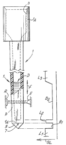
As depicted in the accompanying drawing, 1
indicates a prismatically-shaped test tube of rectangular
section with an upper end 1A forming the seat 3 for a
stopper. The test tube has flat walls and in particular two
walls of greater area and two walls of lesser area, so that
the rectangular section has sides which are more or less
greatly differentiated from each other. The optical
analysis is performed by passing the test tube with a
relative movement between an emitter E of a light ray and a
receiver R of said ray, the ray passing through the lesser
CA 02059070 2002-10-28
20333-353
3c
thickness of the body of liquid that may be held in the test
tube in the reading and analyzing instrument, and its path
being that corresponding to the lesser dimension of the
rectangular section. A relative movement, specifically an
up-and-down movement indicated
- 4. - _ ._ .- _ . . . _ ._.
by the double arrow F of Fig. 2, on the part of the
optical system E and R, makes it possible to check for
the presence of the test tube and of its contents, in
order for example to obtain a check of the transparency
of the biological liquid held in the test tube and the
position of the line of demarcation D between the
nontransparent part (for example the corpuscular part of
the blood) and the transparent part (for example plasma)
of the biological liquid under test.
The improved test tube of the invention possesses
in addition to the thickness of base wall 1A, externally
to and beneath the test tube, an extension 5 in the form
of an optical prism with its edge pointing down and
parallel to the larger walls of the test tube, which
walls transmit the pencil of light energy P between the
emitter E and the receiver R. The prism may be of any
suitable shape and advantageously - 'though not
necessarily - 3.ts active walls may be inclined by
approximately 45° with respect to the-test-tube's plane------- -
of symmetry passing through the edge of the prism 5.
Y
Advantageously, the prism does not project directly from
the intersection between the side walls and the base, but
rather at a .certain distance from the edges of these _
walls with the base, so as to create a step which gives
a sharper differentiation in the optical behavior an
passing between the prism portion and the base wall
portion 1A. . .On this step .there _ , may_._._ also - , be the
irregularities indicated generally by 7 arising from the
point of injection of the thermoplastic material when the
test tubes were formed by molding; these irregularities
have no effect for the purposes of the .indications
supplied by the analy~zng optical system.
The presence of a prism 5 at the base of the test
tube offers many significant advantages. .
The diagram of Fig. 3 shows the amount of light
energy S1a reoeived by the receiver R and passing in the
form of a. pencil of -light ..P through the portion of the
test tube inserted in a measuring instrument and the
portion immediately below the bottom end of this test
~~5~0°~0
- 5 -
tube. ~Jsing the test tube of the inwentian produces a a
first zone of direct passage without attenuation of the
energy of the pencil P and hence a phase L1 of
unattenuated~ light. As soon as the pencil of light
reaches the prism 5 in its relative movement with respect
to the test tube, a sharply defined dark phase B1 is
obtained, due to the change in the direction of the light
beam caused by the prism; there follows a phase L2 caused
by the passing of the light through the transparent
thickness 1A of the test tube base. After the test tube
base 1A, the pencil of light energy P will now pass
through the more or less strongly opaque portion of the
biological liquid under test, held in the test tube,
where the opaque corpuscular part is concentrated; this
produces a dark phase B2 corresponding to the denser and
more opaque column of biological liquid, as far as the
level D of separation between the opaque corpuscular part
and the transparent part of said biological liquid. When
------- - -the-pencil ~of light reaches the level D., a light phase L3
is produced by the more ox less sharp increase in
transparency of the biological liquid above the level of
demarcation D.
_... The light and dark signals.Ll, B1, L2 indicated
above make it possible to perform many reliable checks;
these are made possible by the presence of the prism 5,
which. by changing the direction of the pencil of light
creates the sharp demarcation between the light zones L1
and L2 and the dark zone B1, this last being due to the
change in the direction of the pencil of light caused by
the prism 5. This sequence remains true and valid even if
there is no biological liquid in the test tube.
The sequence of illuminations and interruptions
in the illumination of the receiver R provides in the
first place a check of the efficiency of said optical...
35. system of the instrument, thereby avoiding those
perturbations in the accuracy of the readings which may
be due even to an attenuation in the efficiency _of the .. .
system itself. Another possibility offered by the
arrangement described above is that of precisely reading
- ~ _ 2~~9~~~0
the position of the test tube and hence checking that the
test tube is correctly positioned - which excludes a
reading error due to bad position of the test tube, which
is otherwise difficult to check for from other criteria.
Still another possibility offered by the test tube of the
invention is that of directly checking far the presence
of the test tube using the same signals which among other
things also identify its position. Again, the sharp
separations between the dark zones anal the light zones,
which are offered by the directional change caused by the
prism 5, enable the speed and inertia of response of the
sensor to be checked, particularly by the presence of the
flash of light L2 obtained through the more or less
narrow thickness 1A of the definitely transparent base of
the test tube.
Tt should be noticed that the step between the
test tube base wall 1.A and the prism extension 5 ensures
the clear separation of the dark zone B1 from the light
----- - zone L2, which zones are. quite unaffected. by possible . -. _
irregularities such as those due to the injection points
which, as regards''the irregularities 7, are provided in
the mold for the injection molding of the test tubes
using synthetic thermoplastics..
These and other advantages and possibilities of
reliable checks, offered by the test tube of the
invention, represent an improvement in the functionality
of analytical equipment of the type indicated. , ____ __ ___
It will be understood that the drawing shows only
an illustrative embodiment which is given purely as a
practical demonstration of the invention, it being
possible for said invention to vary as regards shapes and
arrangements without thereby departing from the scope of
-the concept underlying said inventian.